Eurolube 53402 User manual

English Manual for PM-Module 53402, R10, 181008
LUBE-MASTER R10
R10
PM MANUAL
PRINTER MODULE
53402

LUBE-MASTER R10
2(16)
Table of Contents
2. INTRODUCTION......................................................................................................................................................... 3
3. MECHANICAL INSTALLATION ............................................................................................................................. 3
4. ELECTRIC INSTALLATION..................................................................................................................................... 3
5. CONFIGURATION ...................................................................................................................................................... 4
5.1. CHECK BEFORE CONFIGURATION ...........................................................................................................................4
5.2. ADDRESSING THE NEW MODULE.............................................................................................................................4
5.3. IMPORTANT INFORMATION FOR MODULES EQUIPPED WITH FLASH CHIP...............................................................4
5.3.1. Reports based on a time period................................................................................................................4
5.3.2. Full report customisation possibility. ......................................................................................................4
5.4. SET-UP MODE.......................................................................................................................................................4
5.5. CHANGE ADDRESS [PM//ADDRESS]........................................................................................................................5
5.6. RECOMMENDATION FOR SETTING ADDRESSES........................................................................................................5
6. ADMINISTRATE USERS............................................................................................................................................ 5
6.1. ADD A USER [PM//DB/ADDUSER]..........................................................................................................................5
6.2. REMOVE A USER [PM//USERDB/DELUSER]...........................................................................................................6
6.3. REMOVE ALL USERS [PM//USERDB/DELALL]........................................................................................................7
6.4. CHANGE USER INFORMATION.................................................................................................................................7
7. TRANSACTION DATABASE..................................................................................................................................... 7
7.1. DELETE TRANSACTION DATABASE [PM//TRANDB/DELTRAN]................................................................................7
7.2. PRINT ALL TRANSACTIONS [PM//TRANDB/PRNTRAN/ALL].....................................................................................8
7.3. PRINT BY TRANSACTION [PM//TRANDB/PRNTRAN/TRAN]......................................................................................8
7.4. PRINT BY JOB NUMBER [PM//TRANDB/PRNTRAN/JOB]..........................................................................................9
7.5. PRINT BY EMPLOYEE NUMBER [PM//TRANDB/PRNTRAN/EMP]..............................................................................9
8. JOB DATABASE ........................................................................................................................................................ 10
8.1. ADD JOB NUMBER [PM//JOBDB/ADDJOB]...........................................................................................................10
8.1.1. Using wildcard characters. ....................................................................................................................10
8.2. DELETE JOB NUMBER [PM//JOBDB/DELJOB]......................................................................................................10
8.3. DELETE ALL JOB NUMBERS [PM//JOBDB/DELALL].............................................................................................11
9. TANK DATABASE..................................................................................................................................................... 11
9.1. CHANGE NAME FOR A TANK [PM//TANKDB/TANKX/NAME].................................................................................11
9.2. CHANGE VOLUME IN A TANK [PM//TANKDB/TANKX/VOL]...................................................................................12
9.3. CHANGE REORDER VOLUME FOR A TANK [PM//TANKDB/TANKX/RVOL]..............................................................12
9.4. CHANGE STOP VOLUME FOR A TANK [PM//TANKDB/TANKX/SVOL].....................................................................13
9.5. PRINT TANK STATUS [PM//TANKDB/PRN]...........................................................................................................13
10. MENU TREE............................................................................................................................................................... 14
11. FAST MENU CODES................................................................................................................................................. 15
12. TECHNICAL SPECIFICATION .............................................................................................................................. 16
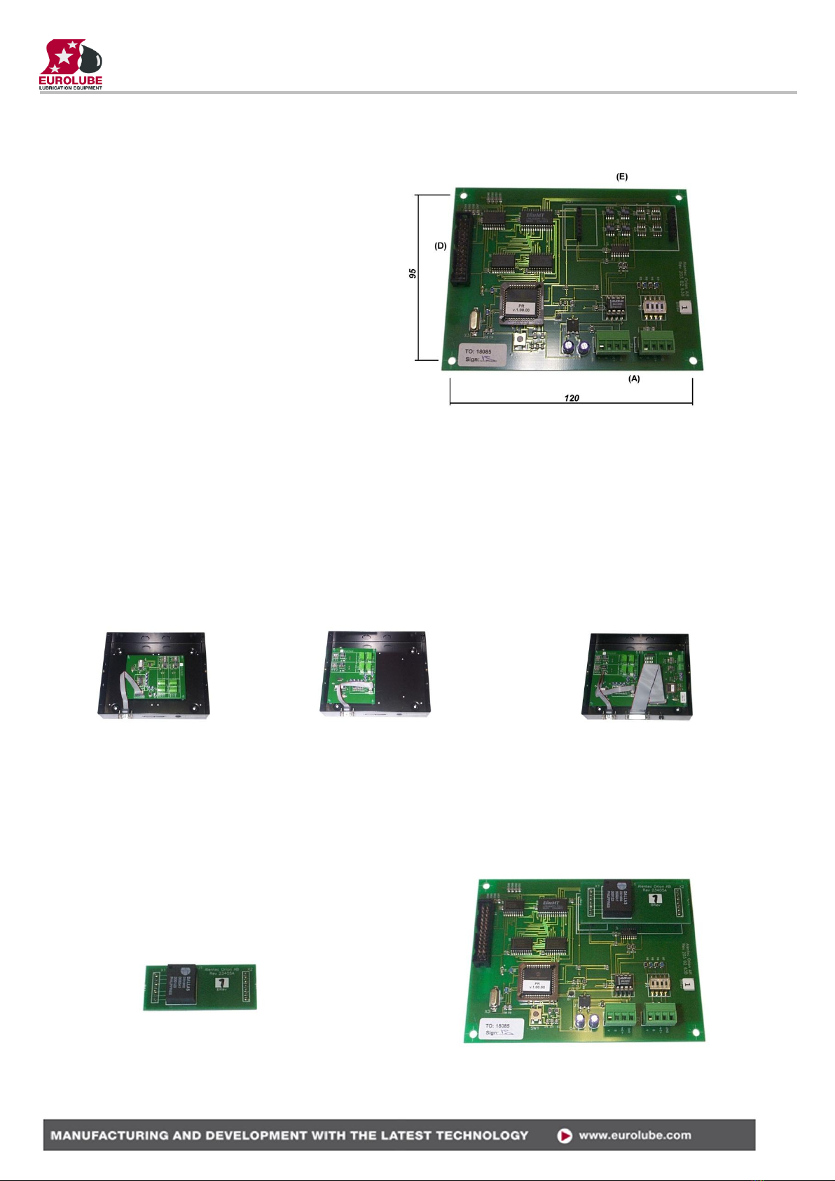
13. PCB PLACED IN A SIO ............................................................................................................................................ 16
14. CLOCK MODULE (CM) MOUNTED ON PM ....................................................................................................... 16

LUBE-MASTER R10
3(16)
2. Introduction
The PM (Printer Module with database) is complement to the LUBE-Master monitoring system. With a PM connected
it is possible to have printouts of dispensed volume, see who made a dispense, type of fluid and on which JOB a
dispense was made.
NOTE! The LUBE-Master Installation guide should be available when installing and configuring a PM.
3. Mechanical installation
The PM is delivered mounted in a metal box.
Complete PM in a box is mounted on a wall or other suitable place using the four-ø5 mm holes in the bottom corners of
the box. The ticket printer (Eurolube part number 53354 or other Centronic parallel printer) should be placed protected
and secure not too far from the module. The printer cable is 2.5 meters.
If a small and compact system is needed the PCB version can be mounted in a MPDM. The chassis-connector on the
flat cable of the printer module is mounted in the “cut-out” hole on the side of the MPDM. See chapter 4.10.
4. Electric installation
The PM has two 4-pin connectors (A) marked A, B, +24 V and Gnd, which are used for the LUBE-Master
communication. Follow the cable recommendations in the LUBE-Master Installation guide. A PM normally gets its
power supply through the communication cable. If the module is placed far away from an MPDM it is possible to apply
an external power-supply to one of the connectors (A).
NOTE! +24VDC may only be applied to one of the connectors.
203 02 63 C (From May 2018)
203 02 63B (To May 2018)
PM200 / 201
PM100 / 101
The RESET button (B) can be used to reset the module or reset the module address.
If the LED (C) flashes it indicates that the MPDM is working. If it is unlit or lit all the time something is wrong.
The short flat printer cable is connected to the parallel port connector marked (D).
Use the two connectors (E) when installing a clock module, pn 53405.
DIL switches for termination and BIAS are marked (F).
Communication driver (G).
Processor speed crystal (H). PM200 / 201 = 25MHz. PM100 / 101 = 4MHz
OBSERVE! To be able to see and configure PM200 / PM201 from a LUBE-Master graphic layout LUBE-
Master R10 must be used. If an older LUBE-Master software version is used it can be updated by
replacing the Engine, adding PM200.ocx and PM201.ocx and then register the PM200.ocx by the
Windows “regsrv32.exe”.
A PM200 and PM201 will work in the system exactly as a PM100 or PM101 even without updating.

LUBE-MASTER R10
4(16)
Reel:SETUP ‡
EXIT STOP CE ENT
PASS:_ ‡
Enter password
Adr:2???_ ‡
Address[code]
PM: ‡
PM MainMenu
5. Configuration
An LUBE-Master configuration sheet should always be filled or altered during the configuration.
NOTE! To obtain technical support a copy of the configuration sheet for the complete installation must be
sent to Alentec & Orion AB at
E-mail: lubemaster@alentec.se
Post: Alentec & Orion AB
LUBE-Master Support Team
Grustagsvägen 4
SE-138 40 Älta
SWEDEN
5.1. Check before configuration
Check that the PM is working and communicating with the system according to the
LUBE-Master Manual chapter "Testing modules".
NOTE! Do not forget to check and adjust the termination and BIAS according to LUBE-Master Manual.
5.2. Addressing the new module
A new module has no address on delivery. To address a new module or one with an unknown address you press and
hold the RESET-button for 5 seconds. This will give the module a temporary address. Next, enter SET-UP-mode on
a KeyPad and press 0 + ENTER to access the Main menu of the module. Find the menu to change module-address
(see below).
NOTE! You can only install one module at a time using this method. If you hold the RESET-button on
multiple units simultaneously only the most recently activated is active.
TIP! Follow preferably ”Recommendation for setting addresses” when setting addresses.
5.3. Important information for modules equipped with FLASH chip.
When we changed from OTP chip (One Time Programmable, white label) to FLASH chip technology we also
added functions that could not be used with OTP chip.
5.3.1.Reports based on a time period.
If you have a printer module already equipped with a FLASH chip or is updating an old one to FLASH chip you
should also add the choices for setting Start Date and End Date in the Fast Menu of a suitable key pad. Fast
menu codes for this can be found in chapter “10. Fast Menu Codes”.
To be able to have report print out the Start Date and End Date must be set so the report period contain
something to print.
The Start Date and End Date could also be set from the basic PM graphic symbol on the PC.
5.3.2.Full report customisation possibility.
The possibility for report customisation was rather limited in the OTP chip version due to lack of program
memory. The FLASH version has a much larger program memory so for printer modules with FLASH chip the
support for report design has been improved a lot.
To make use of this the foundation for the report design must be initialized
properly. Clicking the “Load default” button of the basic PM graphic symbol
on the PC does this.
5.4. SET-UP mode
Type the word ”SETUP” on a Keypad and press ENTER.
Type the password and press ENTER.
Type the address of the LED you want to configure and press ENTER to access
its main menu.
You can add the 4-digit menu code to go directly to the desired menu.

LUBE-MASTER R10
5(16)
PM: ‡
PM MainMenu
Adr:2XXX ‡
Set Address 3???
Adress:2XXX ‡
Set Address 2???
Adr:2XXX ‡
Set Address 2???
Scroll through the module sub menus by pressing or . When the desired menu is shown press ENTER and so on.
5.5. Change address [PM//Address]
Enter the [KP//Address] by pressing ENTER
Press ENTER to show the cursor.
Type the desired address confirm with ENTER.
When the cursor disappears you are finished.
Press EXIT twice to exit set-up.
NOTE! If two or more modules get the same address the system will not
work. In that case you have to change address again.
TIP! Follow preferably ”Recommendation for setting addresses” when
setting addresses.
5.6. Recommendation for setting addresses
Each module demands a unique 16 bit hexadecimal address. There
are some forbidden and some reserved addresses but it is possible to
use all addresses between 0001 and 9999. To make it easier to
support the system we recommend you follow the table to the right.
This means for example that the first PM should have the address
2001 and the next one 2002. . It is a good idea not to use the default
address 2000, it makes it easier to add new PM’s.
NOTE! Do not forget to write all used addresses in the
Configuration sheet to avoid collisions.
NOTE! Addresses 0000 to 0FFF is forbidden and addresses
larger than 9999 are reserved for the system.
6. Administrate users
Stored user information in the database. With the default chip the database can store up to 32 users. (64 if the optional
chip with version 1.01.XX or 2.01.XX is used.))
In a smaller system it is possible to store 16 local users in a MPDM
6.1. Add a user [PM//DB/AddUser]
A user can be a member of eight different groups named A-H. It is possible to make advanced and complex user
rights for dispense points.
EXAMPLE: ”Bob” is a member of groups AB, user ”Stan” is a member of groups BC
and the dispense points is divided into three bays A, B and C. In this case both users can
open dispense points in bay B but only “Bob” can open dispense points in bay A and only
“Stan” can open dispense points in bay C.
Each group is represented by a value shown in the chart to the right. The group value is
calculated by adding the values for each desired group. Group A and E give a group value of (1+16) which are 17.
Address Module
0000 –0FFF Forbidden
1000 –1xxx MPDM
2000 –2xxx PM with database
2999 Pcdatabase (reserved)
3000 –3xxx KeyPad
4000 –4xxx LED-display
5000 –5xxx PLC-Modules
6000 –6xxx Reserved
7000 –7xxx Reserved
8000 –8999 TCM, TSM
9000 –9xxx Reserved
A000 –FFFF Forbidden
Group Value
A 1
B 2
C 4
D 8
E 16
F 32
G 64
H 128

LUBE-MASTER R10
6(16)
PM: ‡
PM MainMenu
UserDB: ‡
PM MainMenu
AddUser: ‡
Add User
Emp:_ ‡
Employe No ????
PIN:_ ‡
PIN code ????
PIN:E ‡
PIN code ????
Group:_ ‡
Group 0-255
Namn:_ ‡
Namn (Max 16 ch)
AddUser: ‡
Add User
PM: ‡
PM MainMenu
AnvDB: ‡
PM MainMenu
AddUser: ‡
Add User
DelUser:_ ‡
Delete User
Emp:XXXX ‡
UP/DOWN ENTER
Emp:XXXX ‡
UP/DOWN ENTER
Name:_ ‡
Name (Max 16 ch)
AddUser: ‡
Add User
Enter menu [PM//UserDB] by pressing twice.
At UserDB: press ENTER.
At AddUser: press ENTER.
Type in the employee number (4 digits) and acknowledge by pressing ENTER.
Type in a PIN code (4 figures) and acknowledge by pressing ENTER. If this PIN
is already in use the display will show the letter E (Error).
Type in a group number (0-255) and acknowledge by pressing ENTER.
Type in a name (16 letters) and acknowledge by pressing ENTER.
Press EXIT three times to leave set-up mode.
NOTE! No confirmation is shown. Test it by opening a dispense with the new
PIN codes.
6.2. Remove a user [PM//UserDB/DelUser]
Enter menu [PM//UserDB] by pressing two times.
At userDB: press ENTER.
At AddUser: press .
Press ENTER to get the cursor.
Select a user to remove using or and press ENTER to acknowledge.
Select the next user and press ENTER or press EXIT three times to exit
NOTE! No confirmation is shown. Test it by opening a dispense with the
deleted PIN codes.

LUBE-MASTER R10
7(16)
PM: ‡
PM MainMenu
TranDB: ‡
PM MainMenu
DelTran:N ‡
Delete All Tran
DelTran:N ‡
Delete All Tran
DelTran:N ‡
Delete All Tran
PM: ‡
PM MainMenu
UserDB: ‡
PM MainMenu
AddUser: ‡
Add User
DelUser:_ ‡
Delete User
DelAll:N ‡
Delete All Users
DelAll:N ‡
Delete All Users
DelAll:N ‡
Delete All Users
6.3. Remove all users [PM//UserDB/DelAll]
Enter menu [PM//UserDB] by pressing two times.
At UserDB: press ENTER.
At AddUser: press .
At DelUser: press .
Press ENTER to get the cursor.
Type Yor 1and then ENTER to acknowledge.
Press EXIT three times to leave Set-Up mode.
NOTE! No confirmation is shown.
6.4. Change user information
It is not possible to change user information in a LUBE-Master system without PC. The user with wrong data has to
be deleted and then added with the correct data.
7. Transaction database
The transaction database can store information about the last 940 transactions. When the database is full the oldest
transaction will be replaced by the new, FIFO.
7.1. Delete transaction database [PM//TranDB/DelTran]
Enter menu [PM//TranDB] by pressing .
At TranDB: press ENTER.
At DelTran: press ENTER.
Type Yor 1and then ENTER to acknowledge.
Press EXIT three times to leave SET-UP mode.
NOTE! This will take about 10 seconds. During this time the PM will not
answer to calls on the communication line.

LUBE-MASTER R10
8(16)
PM: ‡
PM MainMenu
TranDB: ‡
PM MainMenu
DelTran: ‡
Delete All Tran
PrnTran: ‡
Print TranDb
All:N ‡
Print All Trans
All:N ‡
Print All Trans
All:N ‡
Print All Trans
PM: ‡
PM MainMenu
TranDB: ‡
PM MainMenu
DelTran: ‡
Delete Alla Tran
PrnTran: ‡
Print TranDb
All:N ‡
Print All Trans
Tran:0 ‡
From Transaction
Tran:0 ‡
From Transaction
Tran:0 ‡
To Transaction
Tran:0 ‡
From Transaction
7.2. Print all transactions [PM//TranDB/PrnTran/All]
Enter menu [PM//TranDB] by pressing .
At TranDB: press ENTER.
At DelTran: press .
At PrnTran: press ENTER.
At All: press ENTER.
Type Yor 1and then ENTER to acknowledge.
Press EXIT three times to leave SETUP mode.
7.3. Print by transaction [PM//TranDB/PrnTran/Tran]
Enter menu [PM//TranDB] by pressing .
At TranDB: press ENTER.
At DelTran: press .
At PrnTran: press ENTER.
At All: go to Tran: by scrolling with or .
At Tran: press ENTER.
Type the first transaction number and acknowledge with ENTER.
Type the last transaction number and acknowledge with ENTER. If you want to
print only one transaction press ENTER immediately.
EXAMPLE: Typing 50 as first transaction and 100 as last transaction will print
all transactions between 50 and 100.
Press EXIT three times to leave SET-UP mode.

LUBE-MASTER R10
9(16)
PM: ‡
PM MainMenu
TranDB: ‡
PM MainMenu
DelTran: ‡
Delete All Tran
PrnTran: ‡
Print TranDb
All:N ‡
Print All Trans
JOBno: ‡
Per JOBnumber
‡
Per JOBnumber
JOBno: ‡
Per JOBnumber
PM: ‡
PM MainMenu
TranDB: ‡
PM MainMenu
DelTran: ‡
Delete All Tran
PrnTran: ‡
Print TranDb
All:N ‡
Print All Trans
Emp: ‡
Per Employe no
Emp:0 ‡
Per Employe no
Emp:0 ‡
Per Employe no
7.4. Print by Job number [PM//TranDB/PrnTran/Job]
Enter menu [PM//TranDB] by pressing .
At TranDB: press ENTER.
At DelTran: press .
At PrnTran: press ENTER.
At All: go to Job: by scrolling with or .
At Job: press ENTER
Type the Job number and then ENTER to acknowledge.
Press EXIT three times to leave SET-UP mode.
7.5. Print by employee number [PM//TranDB/PrnTran/Emp]
Enter menu [PM//TranDB] by pressing .
At TranDB: press ENTER.
At DelTran: press .
At PrnTran: press ENTER.
At All: go to Emp: by scrolling with or .
At Emp: press ENTER
Type the employee number and then ENTER to acknowledge.
Press EXIT three times to leave SET-UP mode.

LUBE-MASTER R10
10(16)
PM: ‡
PM MainMenu
JobDB: ‡
PM MainMenu
AddJOB: ‡
Add JOB number
‡
Add JOB number
PM: ‡
PM MainMenu
JOBDB: ‡
PM MainMenu
AddJOB: ‡
Add JOB number
DelJOB: ‡
Delete JOB no
JOB:XXXXX ‡
Up/Down ENTER
XXXXX ‡
Up/Down ENTER
JOB:XXXXX ‡
Up/Down ENTER
8. JOB database
The system can be set up to use JOB number validation. This is used to restrict oil dispensing to valid jobs only.
8.1. Add Job number [PM//JobDB/AddJob]
Enter menu [PM//JobDB] by pressing three times.
At JobDB: press ENTER.
At AddJob: press ENTER.
Type the JOB number (max 8 characters) and then ENTER to acknowledge.
Press EXIT three times to leave SET-UP mode.
8.1.1.Using wildcard characters.
If the printer module is equipped with a FLASH chip (yellow label) the use of wild card characters are possible.
This feature can be used to make the system to only accept JOB numbers with a certain layout.
The wild card feature supports three different wildcard placeholders.
?Accepts any alphanumeric character in this position
#Accepts any numeric character in this position
@Accepts any alphabetic character in this position
Below there are some samples of how to use wildcards.
ABC### results in ABC123 valid but not ABC1234 or ABC12D
??????? 7 signs must be typed
SE@@@@ 6 characters is OK as long as it the 2 first are SE
#### 4 or 5 figures are OK
#####
8.2. Delete Job number [PM//JobDB/DelJob]
Enter menu [PM//JobDB] by pressing three times.
At JobDB: press ENTER.
At AddJob: press .
At DelJob: press ENTER.
Type the JOB number (max 16 characters) and then ENTER to acknowledge.
Press EXIT three times to leave SET-UP mode.

LUBE-MASTER R10
11(16)
PM: ‡
PM MainMenu
TankDB: ‡
PM MainMenu
Tank1: ‡
Up/Down ENTER
Name:Oil 1 ‡
Oilname
Oil 1 ‡
Oilname
Name:Olja1 ‡
Oilname
PM: ‡
PM MainMenu
JOBDB: ‡
PM MainMenu
AddJOB: ‡
Add JOB number
DelJOB: ‡
Delete JOB no
DelAll: ‡
Delete all Jobs
DelAll:N ‡
(Y / 1) ENTER
8.3. Delete all Job numbers [PM//JobDB/DelAll]
Enter menu [PM//JobDB] by pressing three times.
At JobDB: press ENTER.
At AddJob: press .
At DelJob: press .
At DelAll: press ENTER.
Type Yor 1and then ENTER to acknowledge.
Press EXIT three times to leave SET-UP mode.
9. Tank database
The tank database in the printer module is contains 8 virtual tanks, each with a separate set of data.
Every time a dispense is made the dispensed volume is subtracted from the volume in the corresponding tank. When the
tank is filled the volume filled must be added to the corresponding volume stored in the tank database.
9.1. Change name for a tank [PM//TankDB/TankX/Name]
Enter menu [PM//TankDB] by pressing four times.
At TankDB: press ENTER.
At Tank1: choose the desired tank by scrolling with or and then press
ENTER to acknowledge.
At Name: press ENTER.
Type the name (max 16 characters) and then press ENTER to acknowledge.
Press EXIT three times to leave SET-UP mode.

LUBE-MASTER R10
12(16)
PM: ‡
PM MainMenu
TankDB: ‡
PM MainMenu
Tank1: ‡
Up/Down ENTER
Name:Oil 1 ‡
Oilname
Vol:1563.50 ‡
Volume ?????.??
Vol:1563.50 ‡
Volume ?????.??
Vol:1563.50 ‡
Volume ?????.??
PM: ‡
PM MainMenu
TankDB: ‡
PM MainMenu
Tank1: ‡
Up/Down ENTER
Namn:Oil 1 ‡
Oilname
BVol:300.00 ‡
Reorder volume
BVol:300.00 ‡
Reorder volume
BVol:300.00 ‡
Reorder volume
9.2. Change volume in a tank [PM//TankDB/TankX/Vol]
Enter menu [PM//TankDB] by pressing four times.
At TankDB: press ENTER.
At Tank1: choose the desired tank by scrolling with or and then press
ENTER to acknowledge.
At Name: go to Vol: by scrolling with or . The content of the tank is shown.
At Vol: press ENTER to show the cursor.
Type the new volume (max 99999.99) and then press ENTER to acknowledge.
Press EXIT three times to leave SET-UP mode.
9.3. Change reorder volume for a tank [PM//TankDB/TankX/RVol]
Enter menu [PM//TankDB] by pressing four times.
At TankDB: press ENTER.
At Tank1: choose the desired tank by scrolling with or and then press
ENTER to acknowledge.
At Name: go to RVol: by scrolling with or .
The present value is shown. At RVol: press ENTER to show the cursor.
Type the new reorder volume and then press ENTER to acknowledge.
Press EXIT three times to leave SET-UP mode.

LUBE-MASTER R10
13(16)
PM: ‡
PM MainMenu
TankDB: ‡
PM MainMenu
Tank1: ‡
Up/Down ENTER
PrnTankDB:N ‡
Print TankDB
PrnTankDB:N ‡
Print TankDB
PM: ‡
PM MainMenu
TankDB: ‡
PM MainMenu
Tank1: ‡
Up/Down ENTER
Name:Oil 1 ‡
Oilname
SVol:100.00 ‡
Stop volume
SVol:100.00 ‡
Stop volume
SVol:100.00 ‡
Stop Volume
9.4. Change stop volume for a tank [PM//TankDB/TankX/SVol]
Enter menu [PM//TankDB] by pressing four times.
At TankDB: press ENTER.
At Tank1: choose the desired tank by scrolling with or and then press
ENTER to acknowledge.
At Name: go to SVol: by scrolling with or .
The present value is shown. At SVol: press ENTER to show the cursor.
Type the new stop volume and then press ENTER to acknowledge.
Press EXIT three times to leave SET-UP mode.
9.5. Print tank status [PM//TankDB/Prn]
Enter menu [PM//TankDB] by pressing four times.
At TankDB: press ENTER.
At Tank1: go to Prn: by scrolling with or and then press ENTER to
acknowledge.
At PrnTankDB: press ENTER.
Type Yor 1and then ENTER to acknowledge.
Press EXIT three times to leave SET-UP mode.

LUBE-MASTER R10
14(16)
10. Menu tree
SETUP <enter>
Adr:2XXX <ENTER>
PM:
DelTran:
PrnTran:
All:
REEL:_
Tran:
Job:
Emp:
AddUser:
DelUser:
DelAll:
Adress:<ENTER> <ENTER>
<EXIT>
Adress: 2???
<ENTER>
UserDB:
JobDB:
TankDB
<ENTER>
<ENTER>
DelAll:N
<ENTER>
TranDB:
<EXIT>
/
<ENTER>
<ENTER>
<ENTER>
AddJob:
DelJob:
DelAll:
Tank1:
TankX:
PrnTankDB:
<ENTER>
Name:
Vol:
RVol:
SVol:<ENTER>
PrnTankDB:N
<ENTER>
Pass: <ENTER>

LUBE-MASTER R10
15(16)
11. Fast Menu codes
With a PC, the LUBE-Master WinTools software and a SIO, you can customise the quick menu that appear when you
press ”?”. To do this, assign a name to the menu, a module address and then a code. Password is optional. This code can
also be used together with the address after you have typed SETUP followed by the password.
For a PM-module it will look like this,
New user 20000260 YYYYY where
YYYYY=password
Part
Function
Address
Code
Comment
Main menu
Change address
0800
Standard
Print all
2000
0221
On delivery
Print by transaction
2000
0221
On delivery
Print by Job
2000
0222
On delivery
Print by user
2000
0223
On delivery
Print tank report
2000
0224
On delivery
Set report period
Set report start date
0225
Set report end date
0226
Tank DB
Update tank volume
28X3
Where X is Tank number
Change fluid name
28X2
Where X is Tank number
Change order point
28X4
Where X is Tank number
Change stop-volume
28X5
Where X is Tank number
Print tank report
0224
User DB
New user
0260
Remove user
0261
Remove all users
0262
JOB DB
New JOB-number
0230
Remove JOB-number
0231
Remove all JOB-numbers
0232
Transaction DB
Remove all transactions
0021
Print transactions
Print all transactions
0220
Print by transaction
0221
Print by JOB
0222
Print by user
0223

LUBE-MASTER R10
16(16)
12. Technical specification
Net ports: 2 pieces of LUBE-Master
ports (A) for data-
communication.
Out ports: 1 piece (D) CENTRONIC for
a parallel printer.
Other: RISC-based microprocessor
EEPROM, 64 KB.
Supply voltage: 24 VAC
Max current: 100 mA
Casing: Strong black powder painted
steel box
Outer measures: 23 x 195 x 55 mm.
Mounting: 4 x ø5mm
CC = 175 x 140 mm
Weight: 1,6 kg (mounted in steel box)
13. PCB placed in a SIO
In a small system or at limited space it is possible to mount a printer / database module PCB in a SIO. To do this the
SIO PCB has to be moved and turned one quarter of a turn, see below:
Make sure the power is turned off.
Turn the SIO PCB a quarter of a turn and place it to the left in the box. Move the plastic distances to the holes that make
it possible to place the PCB as shown in the picture to the left. Do not damage the cabling.
SIO standard SIO moved SIO+PM
14. Clock module (CM) mounted on PM
An LUBE-Master system can be fitted with a real-time clock (CM) to keep track of date and time. The CM can be
mounted either on a PM or a LED in which case it will work as a global clock for the entire system.
NOTE! It is very important to install only one CM in the system
The CM is mounted on a PM by pressing the pins into the
corresponding connector on the PM, see below.
Make sure the pins on the bottom are aligned before pressing.
The pins can be bent slightly if needed.
Date and time are then set with a keypad. See the KP manual.
This manual suits for next models
1
Table of contents
Other Eurolube Control Unit manuals
Popular Control Unit manuals by other brands

Grundfos
Grundfos MIXIT manual

EOS
EOS SBM-IR Modul operating instructions

Maestro Wireless Solution
Maestro Wireless Solution A5100-A user manual

Control Techniques
Control Techniques UD77 DeviceNet Startup guide

Acromag
Acromag AcroPack AP522 user manual

Emerson
Emerson KEYSTONE 60 Series Installation and operation manual