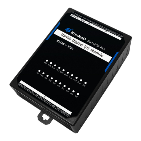
SinoCon KonNaD C2000-A1-SDD1010-AB3 User manual

Last updated: 2020-1-10
C2000-A1-SDD1010-AB3
User Manual
Ethernet ⇋ 1DI + 1DO
Remote I/O Module — Ethernet Digital I/O Module
SinoCon Co., Ltd.

2
4
4
4
5
5
5
8
8
10
11
12
13
13
14
14
14
14
14
14
14
14
14
15
15
16
16
17
17
19
20
21
22
22
24
24
25
26
27
28
29
30
31
32
33
34
Catalog
Catalog
1. Getting Started
1.1. Preparation Before Use
1.2. Wiring
1.3. Software Installation & Device Debug
1.3.1. Software Installation
1.3.2. Device Debug
2. Hardware Description
2.1. Specifications
2.2. Apprearance
2.3. Indicators
2.4. Port Description
2.5. Product Dimensions
2.6. Installation Method
3. Product Features
3.1. DI Data Acquisition
3.1.1. DI Type
3.1.2. DI Data Auto-upload
3.2. DO Control
3.2.1. DO Status
3.2.2. DO Power-on Status
3.3. Other Features
3.3.1. DI Pulse Mode
3.3.2. Filter Parameters
3.3.3. Zeroing
4. Software Tools
4.1. Main Screen
4.2. Use Software
4.2.1. Device Settings
4.2.2. View Device Status
4.2.3. Control Device Status
4.2.4. Remote Settings
5. Protocol
5.1. Registers
5.2. Examples
5.2.1. Read DO Status (0x01)
5.2.2. Write DO Status (0x0F)
5.2.3. Write Single DO Status (0x05)
5.2.4. Read DI Status (0x02)
5.2.5. Read DI Positive Pulse Active State (0x02)
5.2.6. Wirte Single DI Positive Pulse Count (0x06)
5.2.7. Write DI Level Change Count (0x10)
5.2.8. Read DI Status of Cascading Device (0x02)
5.2.9. Write DO Status of Cascading Device (0x0F)
6. Package Contents
7. Warranty Policy
C2000-A1-SDD1010-AB3 User Manual
2 / 34
SinoCon Co., Ltd. www.sinoconsys.com

Copyright Notice
©2000 - 2020 SinoCon Co., Ltd. All Rights Reserved.
Trademarks
The KonNaD logo is a registered trademark of SinoCon Co., Ltd. All other trademarks or registered marks in this
manual belong to their respective manufacturers.
Disclaimer
This document only provides information about KonNaD products. No license to any intellectual property rights is
granted by this document, including any intellectual property licenses, expressed or implied, or by any means.
SinoCon assumes no responsibility other than the liability stated by SinoCon in the terms and conditions of sale of
its products and SinoCon makes no warranties regarding the sale or use of KonNaD products, including the
suitability for the specific use of the products, and marketability, and SinoCon doesn't guarantee that it won't
infringe any patent, copyright or other intellectual property rights, etc.
Information in this document is subject to change without notice and does not represent a commitment on the
part of SinoCon.
Contact US
SinoCon Co., Ltd.
Address: 16th Floor, Tower A, Zhongyin Building, Caitian Road, Futian District, Shenzhen, China
Web: www.sinoconsys.com
Tel: +86 0755-88865168
C2000-A1-SDD1010-AB3 User Manual
3 / 34
SinoCon Co., Ltd. www.sinoconsys.com

1. Getting Started
1.1. Preparation Before Use
You will need the following hardware and software to use the C2000-A1-SDD1010-AB3.
C2000-A1-SDD1010-AB3 module
A power source that provides 9 to 27 VDC, and power wires
A PC running a Windows 7 or later versions, and an Ethernet cable
KonNaD Settings Utility software
1.2. Wiring
Refer to Port Description for the recommended wires.
After the device is powered on, the PWR is steady red, the RUN is flashing, which indicates the device is powered
normally.
Plug the network cable into the Ethernet port of the device, and the other end of the network cable is plugged
into the computer or router. The SPD is steady on, the LINK is flashing, which indicates the device has been
properly connected to the network
C2000-A1-SDD1010-AB3 User Manual
4 / 34
SinoCon Co., Ltd. www.sinoconsys.com

Refer to Indicators for the meaning of LED indicators.
1.3. Software Installation & Device Debug
1.3.1. Software Installation
Download the software on URL: https://www.sinoconsys.com/download/?file=sdk. Unzip the folder and execute
KonNaD.Setup.exe file. The setup wizard will pop up to direct you to complete the installation.
1.3.2. Device Debug
Search Devices
Select Search for Ethernet devices and Click Search to find all devices in the LAN.
Change IP Address
Double-click on the searched device or select the device and click the Set. Set the "Network parameters" of the
device to the same network segment as the computer, set the "mode" to "Server mode", and then click OK.
C2000-A1-SDD1010-AB3 User Manual
5 / 34
SinoCon Co., Ltd. www.sinoconsys.com

Note: The default IP address of the device is 10.1.1.10, and the subnet mask is 255.0.0.0, and the gateway is
10.1.1.200.
Note: If the search fails or prompts the network card to report an error. Check if the status of the network
indicator is normal or replace the network cable.
Communication
After the device parameters are set successfully, search for the device again, and click Refresh in the lower-left
corner of the software to see all the point value of the device.
Read the status of DI: The value 0 indicates "Open", the value 1 indicates "Short to GND". Use a wire to short the
DI1 and GND, you can see that the DI1 indicator is on.
Write the status of DO: The value 1 is close between COM and NO and the DO indicator will be steady on, value
0 is open between COM and NO and the DO indicator will be off. Click on the Pen Icon to control the point value
of the device.
Note:
Refer to Software Tools for more detailed information.
C2000-A1-SDD1010-AB3 User Manual
6 / 34
SinoCon Co., Ltd. www.sinoconsys.com

Refer to Registers for information on "Secondary Development".
C2000-A1-SDD1010-AB3 User Manual
7 / 34
SinoCon Co., Ltd. www.sinoconsys.com

2. Hardware Description
2.1. Specifications
Classification Parameter Specification
Digital Input DI Channels 1
DI Connector Terminal block
Input Type Dry contact
DI Mode Logic level & pulse count
Digital Filtering Time Interval 6 sample periods
Counter Frequency 1kHz
Digital Output DO Channels 1
DO Connector Terminal block
DO Type Form C
DO Mode Logic Level
Contact Capacity 30V/3A
Ethernet No. of Ports 1
Bandwidth 10/100M
Communication Distance 100m
Industrial Protocols Standard Modbus TCP Protocol
Protocol Mode Support TCP Server/Client Mode
Downstream Serial
Port
Serial Standard RS485
No. of Ports 1
Connector Terminal block
Cascade Connection/Transparent
Transmission
RS485 cascade connection
C2000-A1-SDD1010-AB3 User Manual
8 / 34
SinoCon Co., Ltd. www.sinoconsys.com

Power Power Connector Terminal block
Input Voltage 9~27VDC
Current 160mA @ 12VDC
Physical Characteristics Dimensions 75*105*30mm
Installation Din-rail or wall
Environmental Limits Operating Temperature -40℃ ~ 85℃
Storage Temperature -60℃ ~ 125℃
Ambient Relative Humidity 5% ~ 95% RH, non-condensing
Classification Parameter Specification
C2000-A1-SDD1010-AB3 User Manual
9 / 34
SinoCon Co., Ltd. www.sinoconsys.com

2.3. Indicators
Classification Indicator Description Meaning
Digital Input DIx Digital input
indicators (dry
contact)
Steady on:Short to GND
Off:Open
Digital
Output
DOx Digital input
indicators
Steady on:On
Off:Off
Ethernet LINK Network status
indicator
Steady on:Network connection enabled
Flashing:Transmit or receive data
Off:The network port is not plugged into the network
cable
SPD 10/100Mbps
indicator
Steady on:100M network connected
Off:Not connected to the 100M network
Downstream
Serial Port
RXD RS485 data receive
indicator
Steady on:RS485 line fault, please check if the positive
and negative poles of 485 line are reversed
Flashing:RS485 receiving data
Off:RS485 no receiving data
TXD RS485 data
transmit indicator
Flashing:RS485 transmitting data
Off:RS485 no transmitting data
Power PWR Power indicator Steady on:Normal power supply
Off:No power or abnormal power supply, please
check if the voltage range is 9~27VDC
RUN RUN Running indicator Steady on:Device exception
Flashing:Flashes every 1 second when the device is
ready
Off:Device exception
C2000-A1-SDD1010-AB3 User Manual
11 / 34
SinoCon Co., Ltd. www.sinoconsys.com

2.4. Port Description
Classification Port Description Recommended
wiring
Digital Input DIx Digital input RVV 2*0.5
GND Dry contact input common RVV 2*0.5
Digital Output NO Digital output normally open RVV 2*1.0
COM Digital output common RVV 2*1.0
NC Digital output normally close RVV 2*1.0
Ethernet Ethernet RJ45 Ethernet port CAT-5e
Downstream Serial
Port
485+ 、
485-
RS485+, RS485- (downward) RVSP 2*1.0
Power Input V+、V- Power supply input positive, power supply input
negative
RVV 2*1.0
PE Used for reliable grounding of the device, surge
protection
RVV 2*0.5
C2000-A1-SDD1010-AB3 User Manual
12 / 34
SinoCon Co., Ltd. www.sinoconsys.com

3. Product Features
3.1. DI Data Acquisition
3.1.1. DI Type
Dry contact: Short DI and GND, the point value is 1; otherwise the point value is 0.
Note: The start register address of DI status is 10200 (0xC8), 2-byte unsigned integer, and the 0x02 function
code is used to read DI status.
3.1.2. DI Data Auto-upload
After checking the "Auto upload data" item in the software tool, it will actively upload the DI status in 4 cases.
The device is connected to the host computer for the first time
Any DI channel value of the device changes from 1 to 0
Any DI channel value of the device changes from 0 to 1
The device reconnects to the host computer in TCP Client mode after the network is interrupted
3.2. DO Control
3.2.1. DO Status
DO status: Write 0, COM and NO are open and write 1, COM and NO are close.
Note: The start register address of DO status is 100 (0x64), 2-byte unsigned integer, and the 0x01 function
code is used to read DO status, 0x05 function code is used to write single DO status, and 0x0F function code
is used to write multiple DO status simultaneously.
3.2.2. DO Power-on Status
It controls DO status when the device is just powered on and has not received the external control command.
After writing 0, COM and NC are on, and after writing 1, COM and NO are on.
3.3. Other Features
3.3.1. DI Pulse Mode
Positive/negative pulse state
Indicate the current input pulse status. When the DI is open, the positive pulse status register value is set to 1.
When the DI is close, the negative pulse register value is set to 1. Writing 0 will clear the detected pulse state and
writing other values is invalid.
Positive/negative pulse count
Indicate the number of positive/negative pulse changes. The initial value can be written. After writing, it can be
counted from the initial value to the maximum value of 65535, and then it can be re-counted from 0.
Logic level count
Indicate the sum of the number of positive/negative pulse changes. The initial value can be written. After writing,
C2000-A1-SDD1010-AB3 User Manual
14 / 34
SinoCon Co., Ltd. www.sinoconsys.com

it can be counted from the initial value to the maximum value of 65535, and then it can be re-counted from 0.
3.3.2. Filter Parameters
The DI signal must be kept for several sampling periods before it can be confirmed. The default value is 0x6, which
means that 6 sample periods are required to be confirmed. This value can be modified according to the site
conditions, and the range is 0-20.
3.3.3. Zeroing
When set to auto-zero, the DI positive/negative pulse count or DI logic level count value will be automatically
cleared after each reading.
When set to manually clear, DI positive/negative pulse count and DI logic level count value will not be cleared
every time, and need to be cleared manually. (Manually write the value 0 to clear)
C2000-A1-SDD1010-AB3 User Manual
15 / 34
SinoCon Co., Ltd. www.sinoconsys.com

4. Software Tools
4.1. Main Screen
The main screen displays the results of a broadcast search for C2000-A1-SDD1010-AB3.
Main Screen
1. Set: Set the device parameters
2. Remote Set: For Ethernet type devices, when the device is in the LAN but crosses multiple routers and
cannot be searched, the device parameters can be modified through Remote Set.
3. Change Password: Modify password of Ethernet type devices
4. Clear Password: Clear password of Ethernet type devices. If you need to clear the password, please contact
customer service.
5. Assistant: Help you debug the device, including Network Assistant, Serial Port Assistant, Analog
Conversion, Binary Conversion.
C2000-A1-SDD1010-AB3 User Manual
16 / 34
SinoCon Co., Ltd. www.sinoconsys.com

6. Search for Ethernet devices: Used to search Ethernet type devices
7. Search for serial devices: Used to search serial port devices
8. Listening settings: Used to connect the device in client mode to the software tool.
9. Search: Used to search for Ethernet and serial type devices.
10. Devices List: Display all searched devices.
11. Device Information: Display name, IP address, point value, etc. of the device, and you can modify the
point value of the device.
12. Refresh: Used to refresh the point value of the device after it changes.
4.2. Use Software
4.2.1. Device Settings
Select Search for Ethernet devices, and then click Search, the search results are as follows.
Parameters Settings
Double-click the searched device or click the Set to pop up the dialog box to configure the basic parameters of
the device (default IP address 10.1.1.10/subnet mask 255.0.0.0/gateway 10.1.1.200), the device parameters are
described below:
C2000-A1-SDD1010-AB3 User Manual
17 / 34
SinoCon Co., Ltd. www.sinoconsys.com

Obtain IP automatically: If you select it, when the DI detects the change of the connected switch, it will
immediately upload it to the paired device with which the connection is established.
Auto upload data: If you select it, the DHCP server will automatically assign an IP address to the device, but you
still need to manually set the gateway. If not, you need to manually assign an IP address, subnet mask, and
gateway to it.
Mode: It can be set to "Server mode" or "Client mode", in the "Server mode" the device listens for connections
from the client on the specified port. When the device is in the client mode, it must set the server IP and port at
the same time, it will actively connect to the server. Here, the concept of the Socket of the "Server-Client" is not to
be confused with the application's "Server-Client".
Listening port: The listening port waits for the client to connect when the device is in server mode
Server IP or domain name: When the device is in client mode, the server IP address or domain name needs to be
set to connect the device to the server.
Server port: When the device is in client mode, the server port needs to be set to connect the device to the
server.
Cascade Connection Settings
Click Next or Cascading device to enter the "Cascading device" setting item. Here, you can add our RS485 IO
device as a cascade device. If you do not need to cascade the RS485 IO device as a cascade device, the
settings here can be ignored.
C2000-A1-SDD1010-AB3 User Manual
18 / 34
SinoCon Co., Ltd. www.sinoconsys.com

The "cascade connection" refers to the RS485 port of the device connected to our RS485 IO devices, which
originally used Modbus RTU for communication. After cascading, the host computer can read the data of these
cascaded RS485 IO devices through Modbus TCP. Up to 16 RS485 IO devices can be cascaded. When the host
computer uses Modbus TCP to read the data of cascaded devices, to distinguish different 485 devices, it is
necessary to map the 485 address of the device to the unit ID in Modbus TCP protocol. For example, the host
computer reads the data of RS485 IO device with 485 address of 2, and the unit ID in the Modbus TCP data
message sent by the host computer needs to be set to 2.
Click Add to add the cascading device in the pop-up.
4.2.2. View Device Status
After setting the IP address of the device and the computer on the same network segment, click Refresh in the
lower-left corner of the software to see the device point value information, as shown below:
DI Value: Short DI and GND, value is 1; otherwise, the value is 0
DO Status: 0, COM and NO are open; 1, COM and NO are Close
DI Positive/Negative pulse count: Number of pulse changes, readable and writable. When DI Automatic
zeroing is set to "Automatic", the pulse count will be clear automatically after each reading. When DI Automatic
zeroing is set to "Manual", the pulse count will not be clear after each reading (the maximum value is 65535 and
then reset to zero), which needs to be manually cleared (manually write value 0 to clear).
C2000-A1-SDD1010-AB3 User Manual
19 / 34
SinoCon Co., Ltd. www.sinoconsys.com

4.2.3. Control Device Status
The software can change the digital output state of the device by changing the value of the "DO Status". For
example, when the "DO1 Status" is set to 1, the DO1 indicator is on, and when the "DO1 Status" is set to 0, the
DO1 indicator is off.
The "Power on state" of DO can be controlled. When "DO1 Mode" is "Level mode", the "DO1 Power-on state" is
set to 1. After the device is powered off and powered on, the DO1 indicator will be on.
C2000-A1-SDD1010-AB3 User Manual
20 / 34
SinoCon Co., Ltd. www.sinoconsys.com
Table of contents
Other SinoCon Control Unit manuals
Popular Control Unit manuals by other brands

Genebre
Genebre 2103 Installation, operation and maintenance manual
Swegon
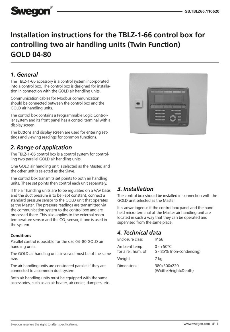
Swegon TBLZ-1-66 installation instructions
Rohl
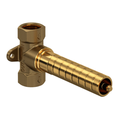
Rohl R1041R instruction manual

Accutrol
Accutrol AVC5000 Installation & operation manual
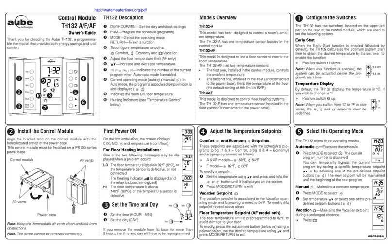
Aube Technologies
Aube Technologies TH132 A owner's guide

Kessel
Kessel Staufix Instructions for installation, operation and maintenance


