Eurolube 117-15 User manual

www.eurolube.com 205203 EUROLUBE EQUIPMENT AB
PART NO 117-15 / ART.NR. 117-15
EJECTOR MIXING UNIT / BLANDNINGSENHET
SERVICE GUIDE
2020-05 ORIGINAL MANUAL
1
General
Equipment for mixing water based uid as Antifreeze
(Glycol/water) Windshield wash and other chemicals.
Tap water is connected with a 1/2”-hose to the valve
inlet thread. Only cold water, max. 40°C is to be used.
To avoid problem in the future an industrial water lter
should be tted into the water line before connected to
the mixing unit. There is a return protection unit tted
between the mixing unit and the closing valve to stop
any attempt to suck mixed uid back into the water
supply piping.
Three separate nozzles for 20%, 33% & 45% mixing are
enclosed. If no nozzle is installed will the mixing rate
be approximate 50-60% depending of viscosity of the
concentrate. For Antifreeze, no nozzle will be tted.
The equipment can be protected by the control panel
53195 and low level sensor 53183. NOTE! If the mixing
unit is installed for mixing explosion dangerous uid,
all electrical equipment and connection have to be
explosion proof.
To supply a dispensing system a stainless steel pump
12740 is suitable. See pump manual for installation and
service.
Allmänt
Utrustning för blandning av vattenblandade vätskor som
kylarvätska (glykol/vatten) eller spolarvätska/vatten
samt andra kemikalier som kan blandas med vatten.
Kranvatten ansluts med en 1/2”-slang till ventilpaketet.
Endast kallt vatten får användas (max 40°C).
För att undvika problem i framtiden bör ett industriellt
vattenlter installeras i rörledningen innan den ansluts
till blandaren.
OBS! Återsugningsskydd behöver ej monteras separat.
Det sitter ett mellan blandningsventilen och den ot-
törmanövrerade avstängningsventilen.
Tre separata munstycken för ändring av blandnings-för-
hållandet medföljer. Blandningsförhållandet kan avvika
från det angivna p.g.a. viskositeten hos koncentratet.
Med spolarvätskekoncentrat blir det ca 20 %, 33 %
samt 45%, respektive. Om inget munstycke är monterat
så blir blandningsförhållandet 50-60 %
Utrustningen kan förses med nivåövervakning, 53170,
och lågnivåvakt, 53183, för koncentratet. OBS! Om man
använder utrustningen för att blanda explosionsfarliga
vätskor som ex.vis spolarvätska och placerar övervak-
ningsenheten i samma rum som koncentratfatet måste
en Ex-säker utrustning installeras. Mellan lågnivågiva-
ren, 53183, och övervakningsenhet, 5t3195, skall då ett
Ex-säkert relä, 23187, monteras och magnetventilen till
pumpen bytas ut mot en Ex-säker ventil, 48080.
För utpumpning till rörledning bör en rostfri pump,
12740, väljas. Se dess manual för skötsel och tekniska
data.
PART NO 117-15
Tank dimensions 500x400x250 mm
Tank volume 48 litres (10 gallons Imperial)
Minimum water pressure 1,7 Bar (24 psi)
Maximum water presssure 10 Bar (145 psi)
Minimum water ow rate 10 l/min
Suction tube L=900 mm ø25 mm
Suction hose L=2,7 m. Dimension 1/2” (12 mm)
Connection from tank 1/2” BSP (f) (G1/2”)
Connection to mixer Hose adapter for 1/2” hose
Nozzle 20% Light brown
Nozzle 33% Black
Nozzle 45% Grey
ART.NR 117-15
Dimension på tank (LxHxD) 500x400x250 mm
Tankvolym 48 liter
Minimum vattentryck 1,7 Bar (24 psi)
Maximalt vattentryck 10 Bar (145 psi)
Minimum vattenöde 10 l/min
Sugrör L=900 mm ø25 mm
Sugslang L=2,7 m. Dimension 1/2” (12 mm)
Anslutning från tank 1/2” BSP (f) (G1/2”)
Anslutning till blandare Slangnippel for 1/2” slang
Munstycke för 20% Ljusbrun
Munstycke för 33% Svart
Munstycke för 45% Grå
TECHNICAL DATA
TEKNISKA DATA
www.eurolube.com
EUROLUBE EQUIPMENT 205203
PART NO 117-15 / ART.NR. 117-15
EJECTOR MIXING UNIT / BLANDNINGSENHET
2
There are three nozzles included. They are designed for mixing windscreen uid. The
light brown nozzle will give ~20% and the black nozzle ~ 33 % and the grey nozzle 45%
when normal windscreen wash uid is in use and min. 10l/min ow.
If a uid with higher viscosity as Anti freeze is in use the mixture will be ~20% with light
brown nozzle and ~30% with black nozzle and without any nozzle the mixture will be
over 50%.
Maximum suction high for concentrate is 1.5 m. Otherwise will the mixture get a faulty
mixing rate.
In some cases due to installation properties it will be necessary to increase the nozzle
hole to receive requested mixing rate. When that happens, drill up the nozzle hole and
check the mixing rate by testing the mixed uid.
If a smaller percentage mixing is desired, nozzle kit 244 10 01 can be ordered. This kit
contains the following nozzles (if mixed with water-thin viscosity:
Tre munstycken medlevereras. Dessa är avsedda för blandning av spolarvätska. Det
ljusbruna munstycket ger ~20%, det svarta munstycket ger ~33% samt det gråa
munstycket ger ~45% med vanlig spolarvätska och minst 10l/min vattenöde.
Om koncentrat med högre viskositet används som ex.vis Glykol ger ljusbrunt munstycke
~20%, svart munstycke ~30% och helt utan munstycke över 50%. Max. sughöjd är 1,5 m
för att angivna värden skall kunna innehållas.
Ibland kan vissa egenskaper runt installation göra det nödvändigt att öka hålet i
munstycket för att erhålla önskad blandning. När andra blandnings-förhållande önskas
borras hålet i munstycket upp så att mer koncentrat kan sugas upp.
Om mindre inblandning önskas kan sats med mindre munstycken beställas,
artikelnummer 244 10 01. Satsen innehåller munstycken som möjliggör följande
blandningsförhållanden (om blandat med vätska med vattenliknande viskositet):
NOTE! Check the closing function at the floater operated water
valve every week to avoid over flow of water.
Check the strainer and water lter regularly and clean if necessary before there are too
much of impurity, which limit the water ow. The mixing unit need at least 10 l/min. If
liquid is coming from the leak hole in the pump, the upper packing is worn or damaged
and need to be replaced immediately. If lye or similar liquid with high PH-value is in use
a small hose can be connected in that hole for leading away harmful gas. Evacuate the
harmful gas from the pump and ventilate well in that area there the hose ends. Check
and clean the tank regularly, for ex every 6-8 month. If there are a low level indicator
connected from the concentrate will that one also be included into the regularly check
procedure. Lift it up from the concentrate container and make sure that the pump is
stopped.
OBS! Varje vecka skall ventilfunktionen kontrolleras så att den
säkert stänger vattenflödet när flottören lyfts upp.
Kontrollera silen och vattenltret med jämna mellanrum och rengör den innan det blir för
mycket föroreningar i den så att vattenödet hindras. För att ejektorn ska kunna fungera
tillfredsställande måste vattenödet överstiga 10 l/min. Om det kommer vätska genom
läckagehålet på pumpen skall de övre packningarna bytas. Om lut eller liknande vätskor,
som är frätande för aluminium, används skall en separat slang anslutas i läckagehålet
med hjälp av en rostfri slangsockel och en lämplig 1/4”-slang. Led bort eventuella gaser
från pumpen och ventilera väl i det utrymme där slangen mynnar. Kontrollera och rengör
tanken med lämplig intervall, 6 – 8 mån. Vid tankkontrollen skall också lågnivågivaren för
koncentratet kontrolleras. Detta görs genom att man lyfter upp den ur koncentratfatet
och konstaterar att pumpen stannar när magnetventilen stänger.
General
Before rst start the air pressure should be reduced down so it will be possible to
start up the pump very gently and slowly. When tubes and hoses are lled and primed
increase the pressure slowly up to working pressure at 5-6 Bar. Check there are no
leakages or strange noises from the pump.
Never start the pump with higher air pressure without ensuring that the entire system
is bled from air. Do not forget to check for leakage in all piping. Even those which could
be located in other part of the workshop.
Allmänt
Före första start skall lufttrycket skruvas ned så att man kan starta pumpen med ett
lågt tryck och när rör och slangar fyllts upp ökas trycket till lämpligt arbetstryck som är
ca 5-6 bar.
Kontrollera att det inte nns något läckage eller konstiga ljud från pumpen. Starta
aldrig pumpen med fullt tryck utan att avlufta hela ledningens längd. Glöm inte att
kontrollera alla rörledningar även dom som nns i andra delar av verkstaden.
FIRST START / FÖRSTA UPPSTARTEN
NOZZLES / MUNSTYCKEN
OPERATION / SKÖTSEL
ORIFICE SIZE (MM) COLOUR / FÄRG RATIO / BLANDNINGSFÖRHÅLLANDE PERCENT / PROCENT
4,75 No tip 1:1 50,0%
3,25 Grey 1.3:1 43,4%
2,49 Black 2:1 33,3%
1,78 Beige 3.5:1 22,2%
1,32 Red 6:1 14,3%
1,09 White 9:1 10,0%
1,02 Blue 10:1 9,1%
0,89 Light brown 13:1 7,1%
0,71 Green 18:1 5,3%
0,64 Orange 25:1 3,9%
0,58 Brown 30:1 3,2%
0,51 Yellow 37:1 2,6%
0,36 Purple 55:1 1,8%
0,25 Pink 110:1 0,9%
www.eurolube.com 205203 EUROLUBE EQUIPMENT
PART NO 117-15 / ART.NR. 117-15
EJECTOR MIXING UNIT / BLANDNINGSENHET
3
Check that the wall is made of an appropriate material for the load. Approx. 55-60 kg.
Hang up the stainless steel tank and check it is level.
Make sure there is a shut-off valve between the water supply and the mixing unit. Use a
1/2” hose in suitable length so no bending or unnecessary tension will occur between
tank and piping.
Water pressure has to be between 1.5 Bar and 5 Bar and water ow has to be over 10 l/
min. The water pressure regulator for the ejector is pre-set to 3 bar. Maximum working
pressure for the ejector is 5 bar. Maximum water pressure connection is 10 bar.
NOTE! Always use protection gloves and protection goggles when
chemicals are in use. Place the concentrate drum near to the mixing unit and
make sure that the drum has a steady and stability without any risk for overturn.
Mount the suction tube in the drum and make sure that the hose is long enough to
reach the inlet at the valve without any extra tension or bending. If necessary cut of all
unnecessary length. To long suction hose can destroy the performance of mixing rate.
Mount the transparent hose after the mixing unit + and let it pass through the hole in the
mixing tank lid. The mixture depends of the choosed nozzle. Put the choosed nozzle in
the hose adapter before the concentrate suction hose is connected. See page 9 position
4.
Place the oor stand or the wall bracket at the choosed position and fasten it at the oor
or at the wall with suitable screws. Mount the pump in the stand/bracket and attach the
suction hose to the outlet adapter from the tank.
Always seal all connections and adapters with Loctite 572 or 577 (or similar). NOTE!
Never use ax or Teon tape.
Connect the delivery hose from the pump to the closing valve at the beginning of
delivery piping. The valve is important for future service and maintenance.
Mount the air lter/regulator in the air supply piping and connect the pump by using the
enclosed air hose and quick coupling.
If a safety device is in use the solenoid valve should be mounted before the air lter/
regulator.
If explosive or re hazardous liquid is in use shall the protection equipment 53430 be
placed at suitable distance from the concentrate drum (or in another room). Connect the
electrical 220V AC, to the box according to the enclosed connection description and
continue with a low-tension cable for 24V to the ex. proof box 53187 and further to the ex
proof solenoid valve.
NOTE! Always check the enclosed instructions enclosed in
respective electrical boxes.
For maintenance and service of the pump, see respective manual.
Kontrollera att väggen är av sådan beskaffenhet att den tål tankens belastning. Ca 55-60
kg. Häng därefter upp den rostfria tanken.
Se till att det nns en avstängningsventil i änden på vattenledningen innan anslutningen
av kallvattnet mot ventilen sker. Använd en mjuk slang i dimension 1/2” så att inga krafter
överförs mellan tank och rördragning.
Vattentrycket skall ligga mellan 1,5 och 10 Bar. Vattenödet måste överstiga 10 l/min.
Förinställt tryck på regulator för vatten till ejektor är 3 bar. Maximalt arbetstryck för
ejektor är 5 bar. Max inkopplingstryck 10 bar.
OBS! Använd alltid skyddshandskar och skyddsglasögon vid
all hantering av kemikalier. Placera kemikaliefatet i direkt anslutning till
doseringsenheten och på ett sådant sätt att den står stadigt och inte riskerar att välta
och förorsaka skada. Montera sugröret i fatets stora öppning.
Se till att slangen räcker upp till kemanslutningen på ejektorn utan onödig spänning
eller onödiga böjar. Kapa bort överskjutande del av slangen då en för lång sugslang kan
orsaka att blandings-förhållandet inte blir det förväntade.
Montera slangen från ejektorn så att den går ned i blandningstanken.
Blandningsförhållandet beror på valt munstycke. Valt munstycke skall monteras i
slanganslutningen på ejektorn. Se bild sidan 9 position 4.
Placera pumpstativet eller väggfästet på ett lagom avstånd från blandningstanken och
kemikaliefatet. Sätt fast stativet/väggfästet med lämpliga fästanordningar. Montera
pumpen, 22770, i stativet/väggfästet och montera sugslangen till utloppet från tanken.
Täta alltid med ytande tätningsmedel som Loctite VVS-tätning eller liknande (Loctite
572 eller 577). OBS! Använd aldrig lin eller teontejp!
Dra utloppslangen från pumpen till rörledningen för den blandade kemikalien och anslut
mot avstängningsventilen som alltid skall avsluta rörledningen. Ventilen är till för att
underlätta vid framtida service och underhåll.
Montera lterregulatorn på luftanslutningens rör och anslut pumpen med den
medföljande snabbkopplingen.
Om ett överfyllnadsskydd används, monteras magnetventilen före
luftbehandlingsaggregatet.
Om explosiva eller brandfarliga vätskor används skall överfyllnadskyddet 53430
monteras på behörigt avstånd (eller i ett annat rum) från kemikaliefatet. Anslut 220 V AC
till den. Dra en lågspänningskabel avsedd för 24 V till ex skyddet, 53187, och vidare till
den ex-säkra magnetventilen.
OBS! Se de speciella inkopplingsanvisningar som finns med i
respektive kopplingslåda.
För skötsel och service av den rostfria pumpen hänvisas till dess
manual
ASSEMBLING AND CONNECTION OF PUMP AND TANK / MONTERING OCH ANSLUTNING AV PUMP OCH TANK
www.eurolube.com
EUROLUBE EQUIPMENT 205203
PART NO 117-15 / ART.NR. 117-15
EJECTOR MIXING UNIT / BLANDNINGSENHET
4
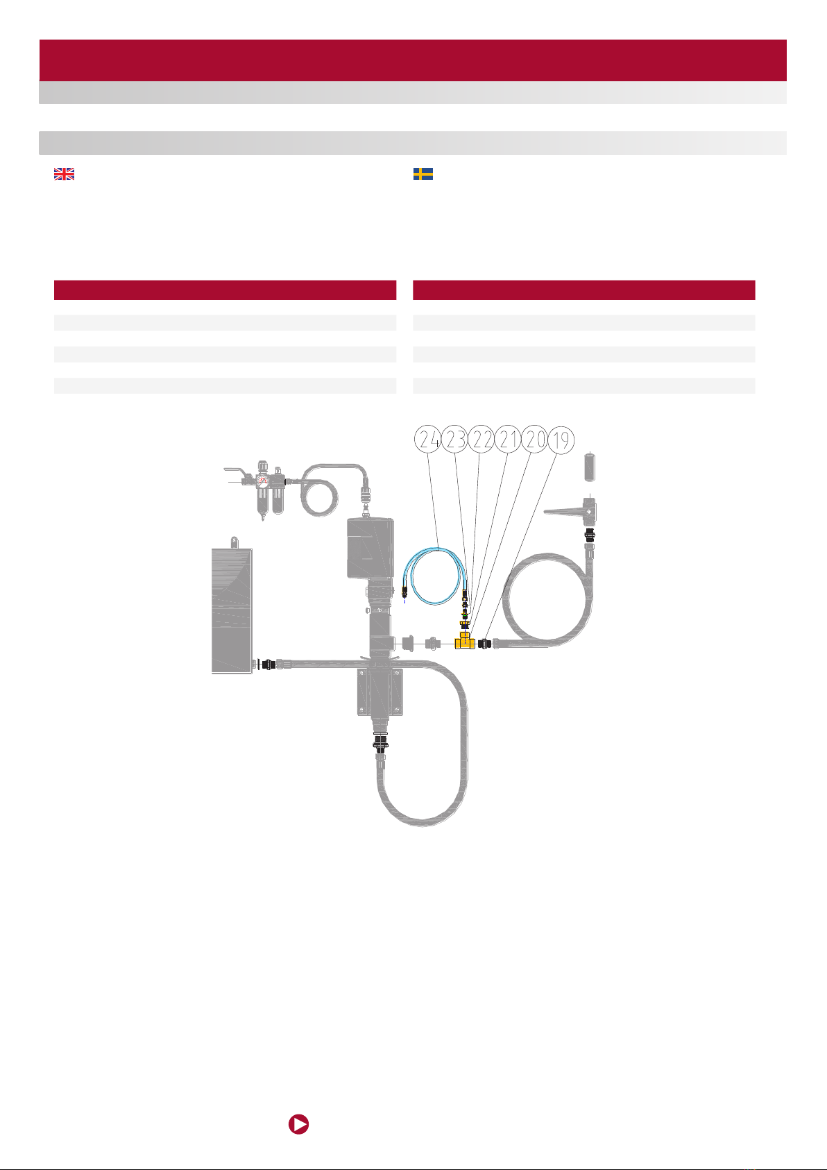
Safety kit 18642 is intended to protect the pipeline and all connected components. The
overpressure is created from the temperature rise in the pipeline. It can be up to 10
Bar/°C when the uid rises in temperature. The safety valve is open at ca 60 bar which
correspond to a temperature rise of ~6 °C. The connection hose can be connected
back to the mix tank or to a separate collection bucket.
NOTE! Never connect that hose to any of the pump connections.
Säkerhetssatsen 18642 är avsedd att skydda ingående komponenter och rörledningen
från övertryck. Det kommer av vätskans temperaturhöjning i rörledningen. Den kan
uppgå till ca 10 Bar/°C när vätskan ökar i temperatur. Säkerhetsventilen öppnar vid ca
60 Bar vilket motsvarar en temperaturhöjning med endast ca 6 °C. Anslutningsslangen
kan kopplas tillbaka till tanken eller till ett separat uppsamlingskärl.
OBS! Får aldrig kopplas tillbaka till någon av pumpens
anslutningar!
SAFETY KIT / SÄKERHETSSATS
POS DESCRIPTION
19 Adapter Stainless steel, 1/2”-1/2” BSP
20 T-connection, 1/2” BSP (f)
21 Reducing adapter, 1/2”-1/4” BSP
22 Safety valve, water based uid. 60 Bar
23 Reducing adapter, 1/4”-1/8” BSP
24 Connection hose 1/4” x1.5 m
POS DESCRIPTION
19 Rostfri adapter, G1/2”-G1/2”
20 T-rör G1/2 inv.
21 Reduceringsadapter, G1/2”-G1/4”
22 Säkerhetsventil, vattenbaserade vätskor, 60 bar
23 Reduceringsadapter, G1/4”- G1/8”
24 Anslutningsslang 1/4” x1,5 m
www.eurolube.com 205203 EUROLUBE EQUIPMENT
PART NO 117-15 / ART.NR. 117-15
EJECTOR MIXING UNIT / BLANDNINGSENHET
5
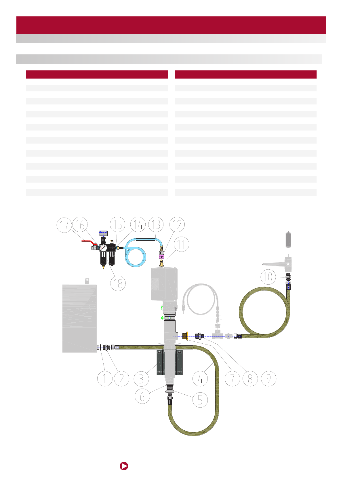
POS DESCRIPTION
1 Rubber steel washer, GBR 1/2”
2 Adapter Stainless steel, 1/2”-1/2” BSP
3Wall bracket
4Suction hose, L=1.5 m
5 Adapter Stainless steel, 1/2”-1” BSP
6 Rubber steel washer, GBR1”
7Reducing adapter 1”-1/2” BSP
8 Adapter Stainless steel, 1/2”-1” BSP
9 Outlet hose, L=1.5 m
10 Adapter Stainless steel, 1/2”-1/2” BSP
11 Air connection nipple
12 Quick coupling
13 Air connection hose, 1/4”-1.5 m
14 Adapter, 1/4”-1/4”BSP
15 Rubber steel washer, GBR 1/4”
16 Adapter, 1/4”-1/4”BSP tapered
17 Air valve, 1/4”BSP
18 Air treatment unit with wall bracket
POS DESCRIPTION
1Gummi-stålbricka, GBR 1/2”
2Rostfri adapter, G1/2”-G1/2”
3Väggfäste
4Sugslang, L=1,5 m
5Rostfri adapter, G1/2”-G1”
6Gummi-stålbricka, GBR 1”
7Reducering G1-G1/2”
8Rostfri adapter, G1/2”-G1”
9Utloppsslang, L=1,5 m
10 Rostfri adapter, G1/2”-G1/2”
11 Luftanslutningsnippel
12 Snabbkoppling
13 Luftanslutningsslang, 1/4”-1,5 m
14 Anslutningsnippel, G1/4”-G1/4”
15 Gummi-stålbricka, GBR 1/4”
16 Anslutningsnippel, R1/4”-R1/4”
17 Avstängningsventil, G1/4”
18 Luftbehandlingsenhet med väggfäste
ASSEMBLING AND CONNECTION OF PUMP AND TANK / MONTERING OCH ANSLUTNING AV PUMP OCH TANK

www.eurolube.com
EUROLUBE EQUIPMENT 205203
PART NO 117-15 / ART.NR. 117-15
EJECTOR MIXING UNIT / BLANDNINGSENHET
6
WATER CONNECTION / VATTENANSLUTNING
The fresh water connection has to be made with a separate closing valve. That valve
is not included into our equipment. Make sure that the water has a good quality and
not polluted with dirt or other foreign particles which can be harmful to the closing
valve or to the mixing unit. If necessary put a separate water lter before the unit. The
connection on the water valve is a ¾”BSP (f) swivelling nut. That connection has a
rubber packing and a small inlet strainer. The valve function is operated by a spring
which closes the water valve when the mixed uid level lifts the oater and releases it.
Sometimes will it be necessary to lubricate the steel arch so it can move freely. Use
some kind of Teon or Silicon grease which is water proof.
There is a restrictor which is placed in the small outlet hose. It is absolute essential for
the mixing function. DO NOT REMOVE OR MODIFY THIS COMPONENT!
Vattenanslutningen skall ha en separat avstängningsventil. Den ingår inte i vår
utrustning. Se till att vattnet har en god kvalitet och att det inte innehåller föroreningar
eller andra partiklar som kan skada vattenventilen eller blandningsenheten. Om det
är nödvändigt kan ett separat vattenlter monteras före enheten. Anslutningen har en
svivlande mutter med G¾” inv. gänga. Anslutningen har en gummibricka för tätning
och en enkel sil. Ventilfunktionen regleras med hjälp av en ottör som yter upp när
nivån i blandningstanken stiger. När den inställda nivån uppnåtts, stänger ventilen
med hjälp av en inbyggd fjäder. Ibland kan det vara nödvändigt att smörja stålbågen
så att den kan röra sig fritt. Använd antingen ett vattenfast Teon- eller silikon- baserat
smörjmedel.
Det sitter en restriktor som sitter i utloppsslangen. Den är absolut nödvändigt
för blandningsfunktionen. TA INTE BORT ELLER MODIFIERA DENNA
KOMPONENT!
Restrictor /
Restriktor
www.eurolube.com 205203 EUROLUBE EQUIPMENT
PART NO 117-15 / ART.NR. 117-15
EJECTOR MIXING UNIT / BLANDNINGSENHET
7
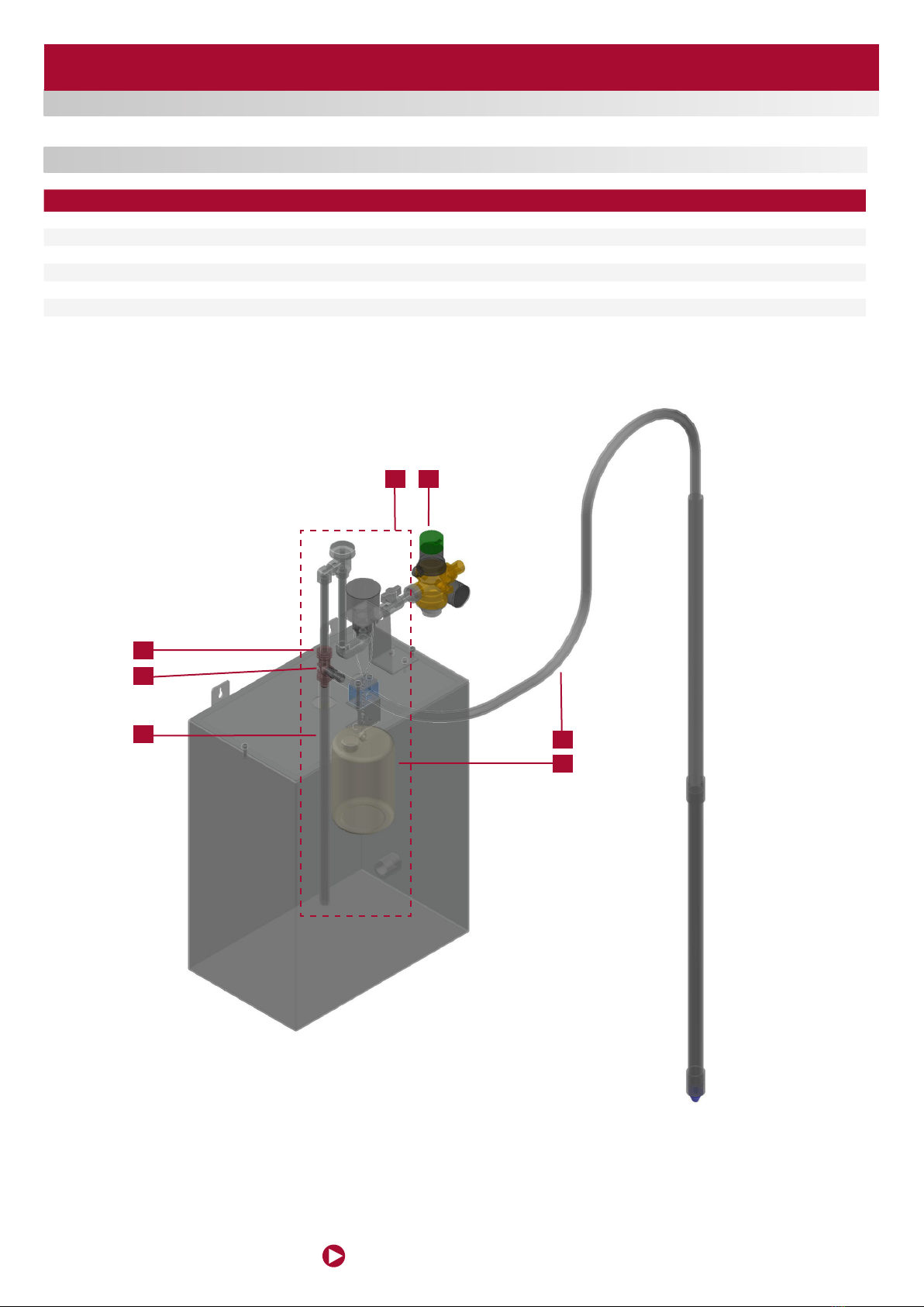
SPARE PARTS / RESERVDELAR
1
3
2
4
56
7
POS QUANTITY / ANTAL DESCRIPTION BESKRIVNING
1171501 1 1 Complete ejector Ejektor komplett
1171502 2 1 Water pressure reducer Vattentrycksregulator
1171503 3 1 Eductor assembly Ejektor
1171504 414 Nozzle (kit) Munstycke (kit)
1171505 5 1 Discharge tube assembly Utloppsrör komplett
1171506 6 1 Suction tube assembly Sugrör komplett
1171507 7 1 Float and chain assembly Flottör och kedja komplett
EUROLUBE EQUIPMENT
Alentec & Orion AB, Grustagsvägen 4, SE-138 40 Älta, Sweden
www.eurolube.com
PART NO 117-15 / ART.NR. 117-15
EJECTOR MIXING UNIT / BLANDNINGSENHET
8
DECLARATION OF CONFORMITY / DEKLARATION OM ÖVERENSSTÄMMELSE
Benny Carlsson,
Product director (Authorized representative for
Eurolube Equipment / Alentec & Orion AB and
responsible for technical documentation).
Produktansvarig (Auktoriserad representant för
Eurolube Equipment / Alentec & Orion AB och
ansvarig för teknisk dokumentation).
Alentec & Orion AB, Grustagsvägen 4, 138 40 Älta Sweden, declares hereby that the
products:
EJECTOR MIXING UNIT / BLANDNINGSENHET PART NO 117-15 / ART.NR. 117-15 are in
conformity with the requirements of the Council´s Machinery Directive 2006/42/EC.
Älta May 11, 2020
Alentec & Orion AB, Grustagsvägen 4, 138 40 Älta, deklarerar härmed att produkterna:
EJECTOR MIXING UNIT / BLANDNINGSENHET PART NO 117-15 / ART.NR. 117-15 är
tillverkade i överensstämmelse med bestämmelserna i Maskindirektivet 2006/42/EC.
Älta Maj 11, 2020
Other Eurolube Industrial Equipment manuals


Popular Industrial Equipment manuals by other brands

4B
4B TouchSwitch TS1V4HT Installation and setup

MDT Technologies
MDT Technologies RF-LK001.03 Technical manual

ABB
ABB HT576688 Operation manual

DCI
DCI DigiTrak Mark III Operator's manual

Redline Engineering
Redline Engineering 500HWC manual

Aerovent
Aerovent IM-502 Installation, operation & maintenance manual


Hubbell
Hubbell PSC2080579 instructions

Electrostatic Technology
Electrostatic Technology 802 manual

Scotsman
Scotsman BL1048S Installation and user manual

Rottler
Rottler SG8 Operation and maintenance manual

Vertiv
Vertiv Liebert DA250 Installer/user guide

DUSTLESS BLASTING
DUSTLESS BLASTING DB150 user manual