EuropAce EWH 16C User manual

Water Heater
EWH 16C
Instrucon Manual
M
A
X
M
A
X
OFF
M
A
X
OFF
Thank you for purchasing EuropAce Water Heater.
For safety purpose, please read this operang instrucon manual carefully before using and keep it for
future reference.
2
Important Safety Informaon
WARNING!
• The product manufactured by us is safe provided they are installed, used and
maintainedingoodworkingorderinaccordancewithourinstruconsandrec-
ommendaons.Alwaysrefertothismanualifyouhaveanydoubt.
• Theproductmustbeearthed.Impropergroundingcouldcauseelectricalshock.
• Ifanyofthefollowingcondionsoccurredasshownbelow,immediatelyswitch
othepowersupplyandcontacttheservicecenterforrepair.Neveraemptto
repairtheproductbyyourself.
−Iftheproductbeginstomakeanoddnoise,smellorsmoke.
−POWERIndicatorLampdoesnotlightup.
−Ifwatertemperaturecannotbecontrolled.
−Iftheproductshowssignsofadisnctchangeinperformance.
−Ifwaterleakfrominsideoftheproduct.
• When the product is used by someone such as child, elderly person, sick person
orphysicallyhandicappedperson,theconcernpersonisrequestedtopayaen-
onandcheckthewatertemperaturebyusinghandfrommetome.Useris
advisedtotestandadjustthewatertemperaturebeforeshowering.
• Inmeoflightningorthunder,switchothepowersupplytotheproductin
advancetoprotecttheproductagainstpossibledamage.
• Theearthconnuityconductoroftheelectricalinstallaonmustbeeecvely
connected to all exposed metal parts of other appliances and services in the
roomwhichtheproductistobeinstalled,toconrmtothelocalregulaons.
NOTE: When removing the product from package, small amount of water may be found
inside. This is normal as the product was tested during manufacturing process.
CAUTION!
• Installaonmustbecarriedoutbyaqualiedpersonnelanditmustbein
compliancetothelocalauthorityregulaons.
• Theproductmustbepermanentlyconnectedtothedirectmainlinesupply.A
plugandsocketarenotrecommendedtobeused.
• Forthecorrectsizeofwireconductorcorrespondingtodierentelectrical
loadings,pleaserefertoWiringLoadingTable.
• Theproductoperatesataminimumwaterowrateof2.0litres/minand
maximumworkingpressureof6bars.Fordirectconneconfromthewatertank,
theproductmusthaveaninstallaonofminimum1.0mbelowthewatertank.
• Theproductwillnotfunconifthereisinsucientwaterow(min2.0litres/
min)totriggertheowswitch.
• Thethermostatwillautomacallycutothepowersupplyifithassensedan
abnormalriseinwatertemperature.

3
Water Heater Overview
7
8
9
10
11
12
3
M
A
X
M
A
X
OFF
M
A
X
OFF
4
5
1. Front Cover
2. POWER Indicator Lamp - RED
3. Temperature Control Knob
4. Stop Valve
5. Mesh Filter
6. Rail Support Cover
7. Rail Support
8. Hand Shower
9. Adjustable Shower Holder
10. Slider Rail
11. PVC Hose
12. Soap Dish

4
Installaon Procedures
HeaterInstallaon
1. Select a suitable posion in the bathroom.
2. Remove the screw at the boom of the Heater.
3. Remove the Front Cover by liing the boom upward.
4. Mark the 3 mounng points of the Heater Base on the wall.
NOTE: The Heater posion should be 1.5m above the bathroom oor.
5. Drill the 3 holes to 34mm depth with 6mm diameter drill bit.
6. Insert the wall plugs and mount the Heater rmly in posion with the screws provided.
AccessoriesInstallaon
1. Fix the Soap Dish, Adjustable Shower Holder and Rail Supports (top and boom) on the
Slider Rail.
2. Mark the 2 mounng points of the Slider Rail Set beside the Heater.
NOTE: It is recommended the top poron of the Rail Support is in level or not higher than
the top of the Heater.
3. Drill 2 holes and mount the Shower Accessories with wall plugs and screws provided.
4. Insert the Rail Support Covers onto the Rail Supports.
HeaterInletandOutletConnecon
This Heater is a single point system and the Water Outlet can only be ed to the PVC Hose
and Hand Shower set provided.
NOTE: No control valve or ng can be ed to the water outlet.
1. Connect the Stop Valve to the Heater Inlet with Rubber Washer provided. Use proper
tools to ghten the connecon and be careful not to break the Plasc Nut.
2. Connect the incoming water pipe (1/2” BSP) to the Stop Valve.
3. Make sure to put the Mesh Filter between Stop Valve and incoming water pipe.
4. If in any case, the Stop Valve is not used or omied, make sure to put the Mesh Filter
between the heater inlet pipe and incoming water pipe.
5. Turn on the water mains to drain out all plumbing dirt and to ll up the heater tank.
NOTE: Do not use white tape during installaon.
WARNING!
• Theheatertankmustbelledupwithwaterbeforethepowersupplyis
switchedon.Thisistopreventdamagetotheheangelement.
6. Connect the PVC Hose and Hand Shower to the heater outlet. Be sure to put in the
Rubber Washer.
7. Hook the Hand Shower to the Adjustable Shower Holder and adjust it to your desired
posion.
8. Check for any water leakage.
WARNING!
• The water inlet and outlet must be installed correctly, otherwise the Heater
cannotfuncon.
• Donotuseplumbingclementonconnecon.Ifnecessary,useonlythreador
sealingtape.

5
ElectricalConnecon
WARNING!
• Theproductmustbeearthed.Impropergroundingcouldcauseelectricalshock.
• Makesuretheelectricalmainsisswitchedobeforecarryingoutanyelectrical
work.
• RefertoWiringLoadingTableforthecorrectcablesize.
• Useatleast2.5mm2doublecoatedcable.
• LeadthepowercablefromtheMCBtoa“ON/OFF”doublepolelinkedswitch
havingacontactseparaonofatleast3mminallpolesoutsidethebathroom,
thenleadacableconnectedtoterminalblockinsidetheunit.(seeFig.2)
1. Insert the cable through the rubber grommet for side entry or wall embedded entry.
2. Connect the cable to terminal block and fully ghten them as follow (see Fig. 3):
BROWN or RED --- LIVE ( L )
BLUE or BLACK --- NEUTRAL ( N )
GREEN or GREEN/YELLOW --- EARTH ( )
WARNING!
• Ensurethewiringconneconiscorrect.
3. Pull out the Temperature Control Knob from the Front Cover.
4. Replace the Front Cover.
5. Replace the Temperature Control Knob and ghten the screw at the boom of the
Heater.
Rail Support Cover
Outlet
Soap Dish
Inlet
Rubber
Washers
M
A
X
M
A
X
OFF
M
A
X
OFF
Fig.
1F
ig. 3
Fig. 2
Note:
Refer to Wiring Loading
Table for electrical loading
and correct size of wire
conductor.
Brown or Red = Live (L)
Blue or Black = Neutral (N)
Green or Green/Yellow
= Earth ( )

6
Wiring Loading Table
Conductor Size (csa)
Voltage (AC) Power (kW) Current (A) mm2Conduit Cable Flexible Cable
On/Off
Switch (A)
Fuse/MCB
(A)
3.3 13.8 2.5 7/0.67mm 50/0.25mm 20 16
3.6 15.0 2.5 7/0.67mm 50/0.25mm 20 20
4.0 16.7 2.5 7/0.67mm 50/0.25mm 20 20
240V~
50/60Hz
5.0 20.8 4.0 7/0.85mm 56/0.30mm 32 32
3.0 13.0 2.5 7/0.67mm 50/0.25mm 20 16
3.3 14.3 2.5 7/0.67mm 50/0.25mm 20 16
4.0 17.4 2.5 7/0.67mm 50/0.25mm 32 20
230V~
50/60Hz
5.0 21.8 4.0 7/0.85mm 56/0.30mm 32 32
2.4 10.9 2.5 7/0.67mm 50/0.25mm 20 16
3.5 15.9 2.5 7/0.67mm 50/0.25mm 20 20
4.5 20.5 2.5 7/0.67mm 50/0.25mm 32 32
5.5 25.0 4.0 7/0.85mm 56/0.30mm 32 32
220V~
50/60Hz
6.0 27.3 4.0 7/0.85mm 56/0.30mm 32 32
Test Run
1. Turn on the water supply and Stop Valve, the water will ow through the Hand Shower.
2. Turn the Temperature Control Knob to “ON”, the POWER Indicator Lamp (RED) will turn
on. The hot water will come out in a few seconds. The higher the temperature indicator
posion, the warmer is the water temperature.
3. The shower might not be hot enough even at the “MAX” posion if the incoming water
supply from the mains is too cold or the pressure is too high. In this case, you can adjust
the Stop Valve to reduce the water inow in order to get the desired water temperature.
4. The height and the direcon of the Shower Holder are adjustable. By depressing the
release buon and slide the Shower Holder to the desired posion.
5. Move the Hand Shower to the desired angle. A ratchet mechanism in the Shower Holder
will hold the Hand Shower in the desired posion.
6. It is not necessary to turn the Temperature Control Knob to “OFF” posion when the
Heater is not in use.
7. Switch o the power supply aer shower.

7
Hand Shower Spray Acon
The adjustable Hand Shower has 3 dierent spray acons. They are Standard, Soothe and
Jumbo. The spray acons are illustrated as follow.
Cleaning and Maintenance
Cleaning the Product
Use only damped cloth with mild detergent to clean the product.
WARNING!
• Donotusethinner,benzeneorotherchemicalproducts.Usingthesesoluons
mayresultindegradaonoftheproductmaterialorcoangremoval.
Clean the Mesh Filter Regularly
Clean the Mesh Filter (see Water Heater Overview) regularly to prevent blockage.
8
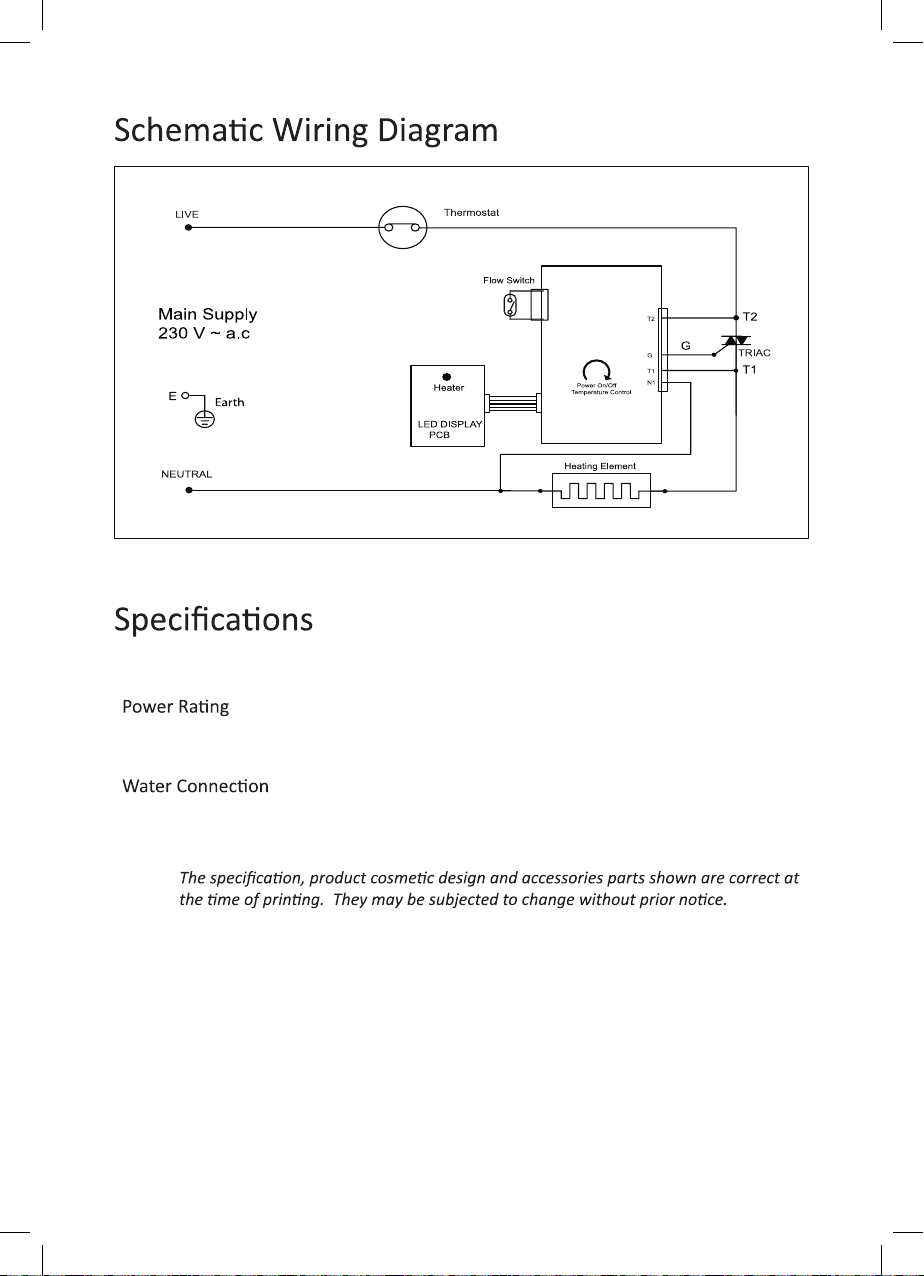
TYPE ELECTRONIC POWER CONTROL
3.3kW 230V~ 50Hz
Min. Water Flow Rate 2.0 Litres/min
Min. Water Pressure 0.1 Bar
1/2” BSP Single Point System
Dimensions 360 x 240 x 84 mm
Weight 3.0kg
NOTE:

Memo

Memo

EUROPACESERVICECENTRE
No.39UbiRoad1,WorldPublicaonsBuilding,#03-00Singapore408695
Tel: (65) 6457 3678 | Fax:( (65) 6741 0728
Email: sales@strategic.com.sg
www.europace.com.sg | www.strategic.com.sg
ThisproductisdistributedbyStrategicMarkeng(S)PteLtd.
If there is any technical amendment for the product, it will be edited on the updated version of the
instrucon manual without prior noce. The pictures shown in the instrucon manual is only for
illustraon purpose only. If the appearance or colour of the product is modied, please refer to the actual
appliance as a standard.
Other manuals for EWH 16C
1
Table of contents
Other EuropAce Water Heater manuals


Popular Water Heater manuals by other brands

MYPV
MYPV ELWA Assembly and operation manual

Mark
Mark TANNER CLA 070 Technical manual

Kenmore
Kenmore 153.330501 owner's manual

Kenmore
Kenmore 153.324190 owner's manual

Chaffoteaux & Maury
Chaffoteaux & Maury Britony FIexiFIue Installation and servicing instrucnions

Kenmore
Kenmore 33916 - 50 Gallon Short Natural Gas Water... owner's manual


PVI
PVI NickelShield Tank Series Specifications

Navien
Navien CR-180 installation manual

Elterm
Elterm Uhlan AsPC-S Operating and assembly manual

Maytag
Maytag SERIES NINE HE2940L user guide

STIEBEL ELTRON
STIEBEL ELTRON DHC 6 EC Operation and installation instructions

Bradford White
Bradford White MITW40L Series Replacement parts list