European Touch Rinato SPA User manual

Document ID: 30080002 Rev: C Technical Support: 800-626-6912 Page 1 of 16

Document ID: 30080002 Rev: C Technical Support: 800-626-6912 Page 2 of 16
TABLE OF CONTENTS
IMPORTANT SAFETY INSTRUCTIONS............................................................................................... 3
DANGER...................................................................................................................................... 3
WARNINGS.................................................................................................................................. 3
IMPORTANT REQUIREMENTS ......................................................................................................... 4
SPECIFICATIONS SUMMARY .......................................................................................................... 4
LOCATION AND SUPPORT ............................................................................................................. 4
LOCATION DIMENSIONS................................................................................................................ 5
ATTACHING THE SEAT BACK AND SEAT BOTTOM CUSHION............................................................. 6
SEAT BACK ATTACHMENT.............................................................................................................6
SEAT MOVEMENT ATTACHMENT.....................................................................................................6
SEAT BOTTOM ATTACHMENT.........................................................................................................6
REMOVING THE SHELLS................................................................................................................ 7
INSTALLING THE FLOOR MOUNTING BRACKETS .............................................................................. 7
REMOVING AND REPLACING DRAIN KNOB...................................................................................... 7
REMOVING AND REPLACING IMPELLER .......................................................................................... 8
WIRED SOUND OPTION................................................................................................................. 8
REPLACEMENT PARTS.................................................................................................................. 9
FULL ASSEMBLY...........................................................................................................................9
FULL ASSEMBLY.........................................................................................................................10
Basin Assembly......................................................................................................................11
POWER DRAIN PUMP ASSEMBLY..................................................................................................12
INLET COVER &RELATED PARTS.................................................................................................12
MOTOR ASSEMBLY .....................................................................................................................13
SEAT MOVEMENT........................................................................................................................13
DRAIN ASSEMBLY.......................................................................................................................14
HIGH CAPACITY PUMP ASSEMBLY................................................................................................14
GENERAL TROUBLE SHOOTING GUIDE ........................................................................................ 15

Document ID: 30080002 Rev: C Technical Support: 800-626-6912 Page 3 of 16
IMPORTANT SAFETY INSTRUCTIONS
When using an electrical appliance, basic precautions should always be followed, including the
following: Read all instructions before using this appliance.
WARNING – To reduce the risk of burns, fire, electric shock, or injury to persons:
1) Use this appliance only for its intended use as described in this manual. Do not use
attachments not recommended by the manufacturer.
2) Never operate this appliance if it has a damaged cord or plug, if it is not working
properly, if it has been dropped or damaged, or dropped into water.
3) Never drop or insert any object into any opening.
4) Do not use outdoors.
5) Do not operate where aerosol (spray) products are being used or where oxygen is being
administered. Save These Instructions
DANGER
1) Never use pins or other metallic fasteners with this appliance.
2) Carefully examine the covering before each use.
3) Discard the appliance if the covering shows any sign of deterioration, such as checking,
blistering, or cracking.
4) Keep electrical components dry – Do not operate in a wet or moist Environment.
WARNINGS
1) Excessive water temperature is dangerous and should be checked before use.
Maximum operating water temperature should not exceed 105°F (41°C) and the
maximum supply water temperature should not exceed 150°F (65°C).
2) The spa has a heated surface in the seat bottom. Persons sensitive to heat must be
careful when using the spa.
3) Always enter and exit the pedicure spa slowly and carefully.
4) Never bring or operate any electrical devices into or near the pedicure spa.
5) This pedicure spa has a weight capacity of 350 pounds.
6) Do Not Crush – Avoid sharp folds.
7) Do not stand on or in appliance.
8) Use only while seated.
9) Keep children away from extended foot support.
10) Connect this appliance to a properly grounded outlet only. See Grounding Instructions
within the install manual.
Note: Always verify maximum temperatures with your local & state codes.

Document ID: 30080002 Rev: C Technical Support: 800-626-6912 Page 4 of 16
IMPORTANT REQUIREMENTS
EUROPEAN TOUCH requires that you contact your local, licensed plumber and licensed
electrician to install your new pedicure spa. Installation must be in compliance with all your
local and state building codes. Your pedicure spa cannot operate efficiently or safely unless it
is provided with adequate electrical power, sufficient water pressure, proper water
temperature, and required drainage capabilities. Contact your local building inspector for
information and local code compliance procedures that need to be followed when having your
pedicure spa installed. Subsequent inspections and approvals that may be required are the
responsibility of the purchaser. (See limited warranty regarding incidental or
consequential exclusions – page 2).
SPECIFICATIONS SUMMARY
Note: Failure to comply with federal, state or local codes and ordinances will result in warranty
being null and void.
WARNING: Shells & front plate MUST be removed prior to moving the Rinato Spa.
Spa shipping configuration removal Spa appearance prior to moving into place
LOCATION AND SUPPORT
Select a level location. The floor structure beneath the pedicure spa must be capable of
supporting the occupied pedicure spa. For the seat back to fully recline, the pedicure spa base
must be mounted 17 inches from the wall as shown below:

Document ID: 30080002 Rev: C Technical Support: 800-626-6912 Page 5 of 16
LOCATION DIMENSIONS

Document ID: 30080002 Rev: C Technical Support: 800-626-6912 Page 6 of 16
ATTACHING THE SEAT BACK AND SEAT BOTTOM CUSHION
Please make sure that all parts are removed from the box before discarding the box. If any parts are missing, you
must contact EUROPEAN TOUCH within 30 days of the delivery date for replacement at 800-626-6912.
Your pedicure spa shipped with the seat back already attached to the spa and with the seat bottom cushion in the
spa shipping box. Follow these instructions to connect the seat back and the seat bottom to the pedicure spa:
Note: 2 people are required to perform the following instructions.
Step 1 Steps 2 & 3
SEAT BACK ATTACHMENT
1. Lift seat back vertically and lower hinge
brackets into position.
2. Align seat back bracket hole for pin
insertion.
3. Insert clevis pin from front and push
through aligned holes. Push hitch pin into
the clevis pin as shown.
Note: Repeat steps two and three for other
side.
Step 1 & 2
SEAT MOVEMENT ATTACHMENT
1. Remove the linear drive hitch and clevis
pins located on the seat back mounting
bracket on the back of the chair.
2. Slide the seat bracket, insert attached,
into the black end on the linear actuator
and line up the holes. Slide the clevis
pin through the holes and secure by
inserting the hitch pin through the small
hole on the clevis pin.
Clevis Pin Hitch Pin
Step 2 Step 3
SEAT BOTTOM ATTACHMENT
1. The seat bottom cushion will be located
in the spa on top of the spa basin.
Remove the seat bottom cushion from
the spa basin.
2. With the chair fully reclined, attach the
seat bottom cushion to the spa, aligning
the seat bottom cushion with the
provided Velcro strips. Ensure that the
rear of the seat bottom cushion is tight
against the seat back.
3. Move seat forward and attach bottom
cushion heater connectors as shown.

Document ID: 30080002 Rev: C Technical Support: 800-626-6912 Page 7 of 16
REMOVING THE SHELLS
To install the shells on your spa follow the instructions below:
Step 1 Step 2
Step 3
1. Remove the front plate from the front of the
spa.
2. Remove each thumb screw (total 2)
3. Slightly lift side panels (total 2) off of the spa
to remove.
INSTALLING THE FLOOR MOUNTING BRACKETS
All Rinato Spas installed with gravity drain and / or hard piped to hot and cold supply lines MUST be anchored to the
floor. Note: Moving spa with flexible hose connected may cause strain and cause leaks.
Step 1 Steps 2 & 3
1. Adjust the leveling feet until you have at
least a ¼” gap between the frame and
leveling foot.
2. Place the floor mounting brackets on to
leveling feet diagonally from each other (2
brackets provided).
3. Mark spots to be drilled. (noted by dot in
image) Bracket has ½” hole. If mounting
to floor, use (2) 3/8” floor lag bolts with
washer (not provided).
REMOVING AND REPLACING DRAIN KNOB
Check your state and local regulations for cleaning procedures. Links to your state boards can be found on our web site,
at www.europeantouch.com. Refer to the Owner’s Manual for “Clean Touch™ Pipe-Free®Spa - Cleaning and
Disinfecting Procedures,” for cleaning recommendations.
To remove the chrome drain handle, loosen the
set screw in the slot on the drain handle and slip
off chrome handle from chrome handle post.
Drain handle removed Drain plunger removed

Document ID: 30080002 Rev: B Technical Support: 800-626-6912 Page 8 of 16
REMOVING AND REPLACING IMPELLER
Check your state and local regulations for cleaning procedures. Links to your state boards can be found on our web site,
at www.europeantouch.com. Refer to the Owner’s Manual “Clean Touch™ Pipe-Free®Spa - Cleaning and Disinfecting
Procedures,” for cleaning recommendations.
1. Remove the Clean Touch
Assembly by turning it clockwise.
2. Remove Clean Touch inlet cover
from housing by twisting counter-
clockwise.
3. Remove the impeller by lifting from
the basin.
4. Once the parts are clean,
complete steps one through three
in reverse order.
WIRED SOUND OPTION
1/8” (3.5mm) Phone
Jack.
Plug in Headphones or
Portable Speakers.
1/8” (3.5mm) Phone Plug
Cable.
Plug into any MP3 Player
or IPOD that has a 1/8”
(
3.5mm
)
Phone Jack.
Stowe away the end of the phone
plug cable in the Massage Remote
Pocket when not in use.

Document ID: 30080002 Rev: C Technical Support: 800-626-6912 Page 9 of 16
REPLACEMENT PARTS
FULL ASSEMBLY

Document ID: 30080002 Rev: C Technical Support: 800-626-6912 Page 10 of 16
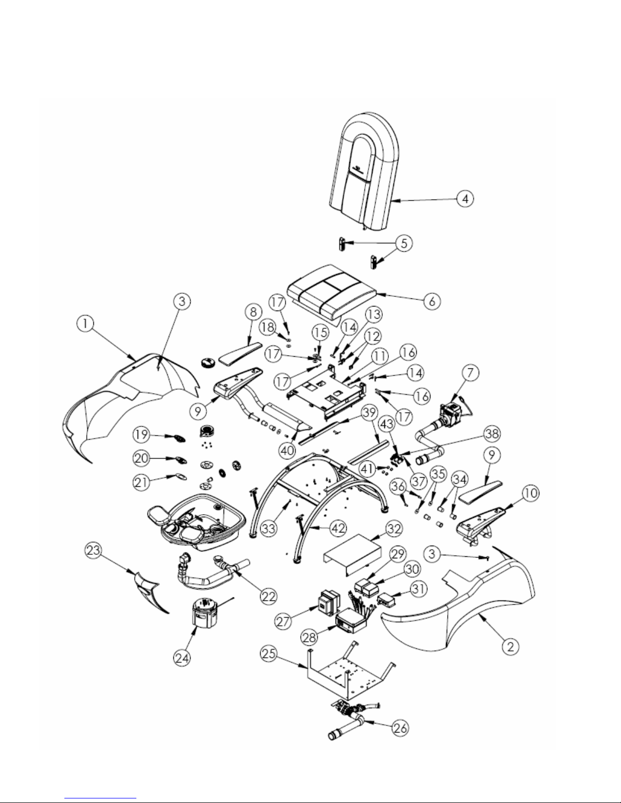
FULL ASSEMBLY
Item
No. Part No. Description Qty.
1 3001310X (3-6) Panel Body RIGHT Rinato (Black, White, Almond, or Gray) 1
2 3001320X (3-6) Panel Body LEFT Rinato (Black, White, Almond, or Gray) 1
3 15130009 Screw Thumb 1/4-20 X 3/4 2
4 3015130X(0-3) Cushion Seat Back Rinato Asm (Black, Burgundy, Almond,
Cashmere) 1
5 25022012 Bracket Seat Back Slide 2
6 3015031X (0-3) Cushion Seat Bottom Asm (Black, Burgundy, Almond, Cashmere) 1
7 30152009 Subasm PDP High Capacity Rinato CT 1
8 2500201X (0-3) Cushion Armrest Platino (Black, Burgundy, Almond, Cashmere) 2
9 25152101 Subasm Armrest RIGHT w/Magnets 1
10 25152100 Subasm Armrest LEFT w/Magnets 1
11 25152013 Subasm Seat Track Platino II 1
12 25022009 Clip Actuator Platino II 2
13 06130009 Hitch Pin 8
14 06130008 Clevis Pin 1-1/2IN X 3/8IN DIA 2
15 25132041 Clevis Pin 1-3/4 X 3/8 DIA 2
16 25132001 Clevis Pin 1-3/4 X 5/16 DIA 4
17 12130041 Bolt 1/4-20 X 3/4 HEX CAP GR5 ZN 4
18 03130012 Washer Air Bleed Fender 4
19 30042000 Two Button Switch CT 1
20 30042001 One Button Switch CT 1
21 30010221 Gasket Button Switch 1
22 30151202 Drain Kit Hard Plumb Assy 1
23 2501230X (1&3) Plate Front Platino II (Platinum or Pearle) 1
24 30152015 Subasm Hanning Motor Next Gen 1
25 30020100 Belly Pan 1
26 30152004 PDP Assembly 1
27 06040220 Transformer Step Down 1
28 30040400 Control Box 1
29 15040013 Transformer Vibration Massage Platino 12V Output 1
30 15040003 Transformer Roller Massage Platino 21V Output 1
31 14040422 Control Box Drain Pump Pipefree SCS 1
32 30020102 Cover Splash 1
33 15130027 Screw 1/4-20 X 1/2 Socket Head Cap 6
34 15020017 Bearing Plain Armrest 8
35 12020274 Washer 3/8 X 1-1/2 OD 4
36 15130013 Bolt 3/8-16 x 1 Hex Cap 4
37 15130000 Bulkhead Fitting for Check Valve 2
38 0613008X(7-8) Washer SCS 7/8 Nylon RED or BLUE 1
39 1500005X(0-3) Skirt Side Seat Cushion (Black, Burgundy, Almond, Cashmere) 2
40 30010300 Shroud Flexible Seat to Frame 1
41 15130016 Check Valve 4
42 30022100 Frame Base NG 1
43 25132013 Bulkhead Fitting 3/4IN Thread 3/4 Barb 1

Document ID: 30080002 Rev: C Technical Support: 800-626-6912 Page 11 of 16
Basin Assembly
Item
No. Part No. Description Qty. Item
No. Part No. Description Qty.
1 15040012 Trim Lock Chrome 1 12 25132004 Bolt Hex Head M8-125 X
20mm SS 2
2 300102XX
(00 – 10) Basin Pipe Free
< Pearl or Platinum> 1 13 02020000 Washer #10 Split Lock 4
3 30150001 Subasm Shower Sprayer 1 14 25132014 Nut M5X0.8 SS HEX PL 4
4 25132100 Faucet Cartridge Rinato 1 15 25002000 Gasket Bushing Plate
Neoprene 2
5 25022014 Escutcheon Sprayer 1 16 12000216 I-Glide Bushing Leg 2
6 30152002 Subasm Footrest Asm 2 17 15000006 Gasket Drain Assemble 3
7 25152016 Bushing Footrest Platino II 2 18 25022003
B
ushing Support Plate -RIGHT 1
8 01030001
Decal - "Do Not Stand In
Basin" 1 19 25022002 Bushing Support Plate -LEFT 1
9 03130012 Washer Air Bleed 2 20 30020209 Stop Footrest Rinato 2
10 14130006 Washer Lock Split 3/8 SS 2 21 25022001 Footrest Mount Plate 1
11 06130070 Screw #10-32x ½ FH Phil 2 22 30020200 Cap ¼ NPT Thread 1

Document ID: 30080002 Rev: C Technical Support: 800-626-6912 Page 12 of 16
POWER DRAIN PUMP ASSEMBLY
Item
No. Part No. Description Qty. Item
No. Part No. Description Qty.
1 14040477 CORD POWER DRAIN PUMP 1 9 12010177 3/4 CLEAR BRAIDED HOSE 1
2 08040005 PUMP PDP 110V DPO 40 1 10 12130091 #10 HOSE CLAMP 2
3 12010235 CONNECTOR 1.5IN X 1.25IN 1 11 14010113 COUPLER 1" IN 1
4 30010218 COUPLER 1.5" TO 1.5" W/CLAMPS 1 12 12130041 BOLT 1/4-20 X 3/4 HEX 1
5 30010217 DRAIN WASTE EXTENSION 1 13 25132005 WASHER M8 1
6 25132008 ADAPTER 1 IN TUBE TO 1 IN PIPE 1 14 30020103 BRACKET PDP SHORT 1
7 25132006 CHECK VALVE 1IN FNPT 1 15 12130048 NUT 1/4-20 NYLON CAP LOCK 1
8 25132007 ADAPTER 3/4 IN TO 1 IN 1
INLET COVER &RELATED PARTS
Item
No. Part No. Description Qty.
1 300102XX
(07, 14) Cover Inlet Housing
< Pearl or Platinum > 1
2 300102XX
(40, 41) Housing Inlet Asm
< Platinum or Pearl > 1
3 30010203 Impeller CT 1
4 30010030 Plate Mounting CT 1
5 30010208 Gasket Inlet Housing CT 1

Document ID: 30080002 Rev: C Technical Support: 800-626-6912 Page 13 of 16
SEAT MOVEMENT
ITEM
NO.PART NO. DESCRIPTION QTY.
1 25022007 Seat Track 1
2 15040405 Linear Drive 50mm Back 1
3 15040414 Linear Drive 140mm Seat 1
4 03130031 Seat Rail Without Latch 2
5 06130009 Hitch Pin 2
6 06130008 Clevis Pin 1-1/2in X 3/8in Dia 2
7 03130043 Bolt Carr 5/16 X 1/2 4
8 01130005 Nut Lock 5/16-18 4
9 15040409 Control Box Seat Movement 1
MOTOR ASSEMBLY
Item
No. Part No. Description Qty.
1 30040200 Motor Hanning Fanless 1
2 30010202 Shaft Impeller 1
3 14000000 Seal Top Pipe Free 1
4 30010209 Gasket Motor Face Plate 1
5 14000001 Seal Bottom Pipe Free 1
6 30010206 Shield Drip NG 1
7 14040265 Sensor Footplate Detection 2
8 30010204 Faceplate Mounting 1
9 30010226 Shroud Motor 1
10 30041400 Wire Ground Yellow-Green 1
11 12010584 Cable Ties (not shown) 4
12 02020000 Washer #10 Split Lock 4
13 12130003 Screw #10-32x .50 PH 4
14 30040403 Cable Double Harness Sensor 1

Document ID: 30080002 Rev: C Technical Support: 800-626-6912 Page 14 of 16
DRAIN ASSEMBLY
Item
No. Part No. Description Qty.
1 30010225 SHOE WASTE 1
2 30010222 OVERFLOW ASM 1
3 30020202 STRAINER DRAIN 1
4 30010224 TUB LOCK GASKET 1
5 30020203
LOCKING PLATE
OVERFLOW 1
6 30020205 HANDLE CONTROL 1
7 30020201 THREADED WASTE BOLT 1
8 30020204
NIPPLE INTERNAL
THREAD 1
9 30020206 CABLE DRAIN 1
10 30020208 STOPPER (CHROME) 1
11 30010227
GASKET STOPPER
RINATO 1
HIGH CAPACITY PUMP ASSEMBLY
Item
No. Part No. Description Qty.
1 12020192 1/2 FPT X 1/2 MPT 90
ELBOW 1
2 30010223 DRAIN WAST EXTENSION
FOR HC PDP 1
3 30010218 COUPLER 1.5" TO 1.5"
WITH CLAMPS 2
4 06010024 SCS 1/2 X 1/2 FPT
COUPLER 1
5 08010004 NIPPLE PVC FTG PDP 1
6 15130028
BUSHING REDUCING 1 1/4
IN X 1/2 IN 1
7 15130022 HOSE 48 IN RUBBER
PLATINO 1
8 30020104
BRACKET HIGH CAPACITY
PUMP 1
9 08040001 PUMP PDP 110V 1
10 15130029 CLAMP TUBE 6 1/2 IN 1

Document ID: 30080002 Rev: C Technical Support: 800-626-6912 Page 15 of 16
GENERAL TROUBLE SHOOTING GUIDE
Problem Description Resolution Reference
No Water
Movement
On/Off Button Not Blinking
Impeller not in place
On/Off Blinking Power Button
1) Verify unit is plugged in to live wall outlet.
2) Verify motor is plugged in to gray control box.
3) Verify fuse in the gray control box is in tact.
4) Verify the wires to the button are not cut.
5) Remove clean touch assembly and verify the impeller is in
place.
6) Ensure that the clean touch assembly is properly attached to
the basin.
7) Ensure that the black sensor underneath the front of the basin
is plugged in.
(1)
(2)
(3)
(4)
(5)
(6)
(7)
Chair
Functions
are not
working
1. Seat Back
a. Roller Massage does not
move up and down.
b. Seat Back –Vibration feature
not working.
2. Seat Cushion – Heat portion of
the seat not working.
8) If the remote does not light up when pressed to operate seat
functions, verify that remote is plugged in.
9) If the remote lights up, but functions do not work, contact
European Touch Customer Service.
(8)
(9)
Water Not
Draining
Chair does not drain properly
having only the standard drain,
(No PDP).
Chair does not drain properly
having a PDP.
10) Make sure plunger is set tall enough to allow water to pass
through.
11) Check for plugged drain and clear if clog is found.
12) If the LED light is On and the pump is heard, check for
plugged drain and clear if clog is found.
13) If the LED light is On and the pump is NOT heard, verify drain
pump is properly connected to the black control box.
(10)
(11)
(12)
(13)
Water not
working or
pressure is
low
The water sprayer is not working
or very little water comes out of
the sprayer head
14) Verify water supply is On.
15) Check for loose water connections under the basin and at the
rear of the chair.
16) Unscrew the sprayer head from its hose and verify screen is
clear.
(14)
(15)
(16)
Basin
Losing
Water
The basin continually loses water
either quickly or over long period
of time
17) Check drain plunger for tears in rubber gasket.
18) Verify drain plunger height is correct and bolt below plunger
is tight.
19) Verify drain strainer is tight.
(17)
(18)
(19)
CONTACT EUROPEAN TOUCH TECHNICAL SUPPORT AT 1-800-626-6912 WITH ANY ISSUES THAT CANNOT BE
RESOLVED USING THIS TROUBLESHOOTING GUIDE.

Document ID: 30080002 Rev: C Technical Support: 800-626-6912 Page 16 of 16
EUROPEAN TOUCH
8301 W. Parkland Court
Milwaukee, WI 53223
Phone Number: 414-357-7016
Toll Free: 800-626-6912
Fax: 414-357-6360
Web Site: www.europeantouch.com
Email: info@europeantouch.com
Other manuals for Rinato SPA
1
Table of contents
Other European Touch Pedicure Spa manuals

European Touch
European Touch Petite Portable Pedicure Spa User manual

European Touch
European Touch Petite Spa User manual

European Touch
European Touch Petite Spa User manual

European Touch
European Touch RINATO XL SPA User manual

European Touch
European Touch Espresso Spa User manual

European Touch
European Touch PORTABLE SPA User manual

European Touch
European Touch FORTE SPA User manual

European Touch
European Touch Pedicure Spa User manual