Euroscan RX2-6 User manual
EUROSCAN RX2-6 / TX2-6
Cabin and trailer recorder
USER MANUAL

EUROSCAN RX2-6 / TX2-6
USER MANUAL
EN-MAN-0042.02
1 of 28
Mai 15, 2014
TABLE OF CONTENTS
INTRODUCTION.......................................................................................................4
Data security .....................................................................................................................................4
Menu 1 Print menu......................................................................................6
1.1 Select compartment to print..........................................................................................6
1.2 Time zone offset for printing.........................................................................................6
1.3 Print event report..........................................................................................................6
1.4 Print parameter report ..................................................................................................6
1.5 Set print date................................................................................................................6
1.6 Delivery ticket settings..................................................................................................6
1.7 Print time period ...........................................................................................................7
1.8 Day start time...............................................................................................................7
1.9 Day end time................................................................................................................7
Menu 2 Alarm settings ...............................................................................8
2.1 Compartment 1.............................................................................................................8
2.2 Compartment 2 (same as Compartment 1)...................................................................8
2.3 Compartment 3 (same as Compartment 1)...................................................................8
2.4 Compartment 4 (same as Compartment 1)...................................................................8
2.5 Digital input 1................................................................................................................8
2.6 Digital input 2 (same as Digital input 1).........................................................................8
2.7 Digital input 3 (same as Digital input 1).........................................................................8
2.8 Digital input 4 (same as Digital input 1).........................................................................8
2.9 Alarm output test ..........................................................................................................8
Menu 3 User settings menu.......................................................................9
3.1 Set time........................................................................................................................9
3.2 Summer/Winter time correction ....................................................................................9
3.3 Set date........................................................................................................................9
3.4 Select language............................................................................................................9
3.5 Set display contrast......................................................................................................9
3.6 Set display backlight.....................................................................................................9
3.7 Set buzzer volume......................................................................................................10
3.8 Set buzzer frequency..................................................................................................10
3.9 Set buzzer on-time .....................................................................................................10
3.x TMS X2 V2.08............................................................................................................10
Menu 4 Status menu.................................................................................11
4.x Parameter menu.........................................................................................................11
Menu 5 Temperature input settings ........................................................12
5.1 T1 input > On/Off...................................................................................................12
5.1.1 Type...........................................................................................................................12
5.1.2 Name (sensor)............................................................................................................12
5.1.3 Name (free text) .........................................................................................................12
5.2 T2 input > on/off, menu structure as 5.1 ................................................................12
5.3 T3 input > on/off, menu structure as 5.1 ................................................................12

EUROSCAN RX2-6 / TX2-6
USER MANUAL
EN-MAN-0042.02
2 of 28
Mai 15, 2014
5.4 T4 input > on/off, menu structure as 5.1 ................................................................12
5.5 T5 input > on/off, menu structure as 5.1 ................................................................12
5.6 T6 input > on/off, menu structure as 5.1 ................................................................12
Menu 6 Digital inputs settings.................................................................13
6.1 Digital input 1 > On/Off...........................................................................................13
6.1.1 Name > Refrigeration ............................................................................................13
6.1.3 Active > high/low ..................................................................................................13
6.1.4 Alarm > On/Off .....................................................................................................13
6.1.5 Store position when input active/inactive or both........................................................14
6.2 Digital input 2 > On/Off, menu structure as 6.1.......................................................14
6.3 Digital input 3 > On/Off, menu structure as 6.1.......................................................14
6.4 Digital input 4 > On/Off, menu structure as 6.1.......................................................14
Menu 7 Compartment settings ................................................................15
7.1 Compartment 1 > On/Off .......................................................................................15
7.1.1 Compartment name > (compartment 1)..................................................................15
7.1.2 Print T1 > Yes/No.................................................................................................15
7.1.3 Alarm on T1 > Yes/No............................................................................................15
7.1.4 Print T2 > Yes/No.................................................................................................15
7.1.5 Alarm on T2 > Yes/No ............................................................................................15
7.1.5.1 Store position when alarm T2 active > Yes/No ...........................................................15
7.1.6 Print T3 > Yes/No.................................................................................................15
7.1.7 Alarm on T3 > Yes/No............................................................................................15
7.1.8 Print T4 > Yes/No..................................................................................................16
7.1.9 Alarm on T4 > Yes/No............................................................................................16
7.1.10 Print T5 > Yes/No..................................................................................................16
7.1.11 Alarm on T5 > Yes/No............................................................................................16
7.1.12 Print T6 > Yes/No..................................................................................................16
7.1.13 Alarm on T6 > Yes/No............................................................................................16
7.1.13.1 Store position when alarm T6 active > Yes/No...........................................................16
7.1.14 Store position on COMPARTMENT ALARM >NO ......................................................16
7.1.15 Print D1 > On/Off...................................................................................................16
7.1.16 Print D2 > On/Off...................................................................................................16
7.1.17 Print D3 > On/Off...................................................................................................16
7.1.18 Print D4 > On/Off...................................................................................................16
7.2Compartment 2, 3 and 4 > On/Off, menu structure as menu 7.1...............................16
Menu 8 Alarm settings .............................................................................17
8.1 Alarm Group 1 > On/Off..........................................................................................17
8.1.1 Name > Frozen......................................................................................................17
8.1.3 Temperature upper limit .............................................................................................17
8.1.4 Temperature lower limit..............................................................................................17
8.1.5 % upper limit...............................................................................................................17
8.1.6 % lower limit...............................................................................................................17
8.1.7 Initial Delay time > 120 min......................................................................................17
8.1.8 Delay time > 60 min................................................................................................17

EUROSCAN RX2-6 / TX2-6
USER MANUAL
EN-MAN-0042.02
3 of 28
Mai 15, 2014
8.2 Alarm Group 2 > On/Off, menu structure as menu 8.1............................................17
8.3 Alarm Group 3 > On/Off, menu structure as menu 8.1............................................17
8.4 Alarm Group 4 > On/Off, menu structure as menu 8.1............................................17
8.5 ALARM BEHIND PIN..................................................................................................17
8.6 OUTPUT FUNCTION.................................................................................................17
8.7 alarm repetitions.........................................................................................................18
8.7.1 Interval of alarm repetitions ........................................................................................18
8.7.2 Alarm output time span...............................................................................................18
Menu 9 Printer settings............................................................................19
9.1 Graph upper limit > +50 °C......................................................................................19
9.2 Graph lower limit > -30 °C .......................................................................................19
9.3 Graph mm per hour > 10 mm ..................................................................................19
9.4 User menu > Yes/No.............................................................................................19
9.5 Delivery ticket setting..................................................................................................19
9.6 Print time period > 10 hours....................................................................................19
9.7 Day start time > 06:00 ............................................................................................19
9.8 Day end time > 18:00 .............................................................................................19
Menu 10 General settings ..........................................................................20
10.1 Temperature unit > °C/°F.........................................................................................20
10.2 Date format > dd/mm/yyyy or mm/dd/yyyy............................................................20
10.4 Sample rate > minute(s) .........................................................................................20
10.5 Vehicle ID > ABCDEF.............................................................................................20
10.6 Header text > Abcdef..............................................................................................20
10.7 Customer ID > ().....................................................................................................20
10.8 Pin number > 1111 (default pin code).....................................................................20
10.9 Correct. factor > Recommended: XX / Setting: +/-X.................................................20
10.10 Serial number > 12400005 ....................................................................................20
Menu 11 Communication settings.............................................................21
11.1 COM 1........................................................................................................................21
11.2 COM 2........................................................................................................................22
11.3 COM 3........................................................................................................................22
11.4 COM 4........................................................................................................................22
Attachment A Technical data.............................................................................23
Attachment B Replace paper roll.......................................................................24
Attachment C Error codes..................................................................................25
Attachment D Factory settings……………………………………………………26

EUROSCAN RX2-6 / TX2-6
USER MANUAL
EN-MAN-0042.02
4 of 28
Mai 15, 2014
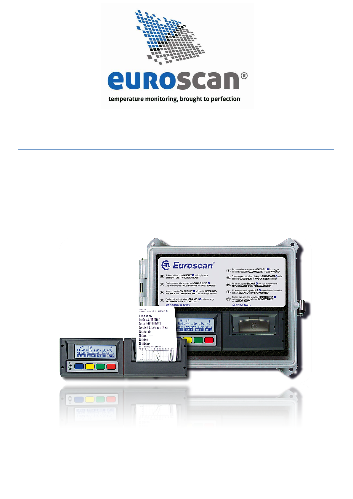
INTRODUCTION
This manual is a user guideline for the use of the EUROSCAN RX2-6/TX2-6 6 sensor temperature
recorders. To avoid guarantee exclusion due to incorrect installation, it is essential to follow the instructions
and recommendations in the installation manual.
EUROSCAN RX2-6 and EUROSCAN TX2-6 temperature recorders are developed and produced to
conform to the applicable European and National guidelines, for the delivery of chilled and frozen transport
goods in transport vehicles.
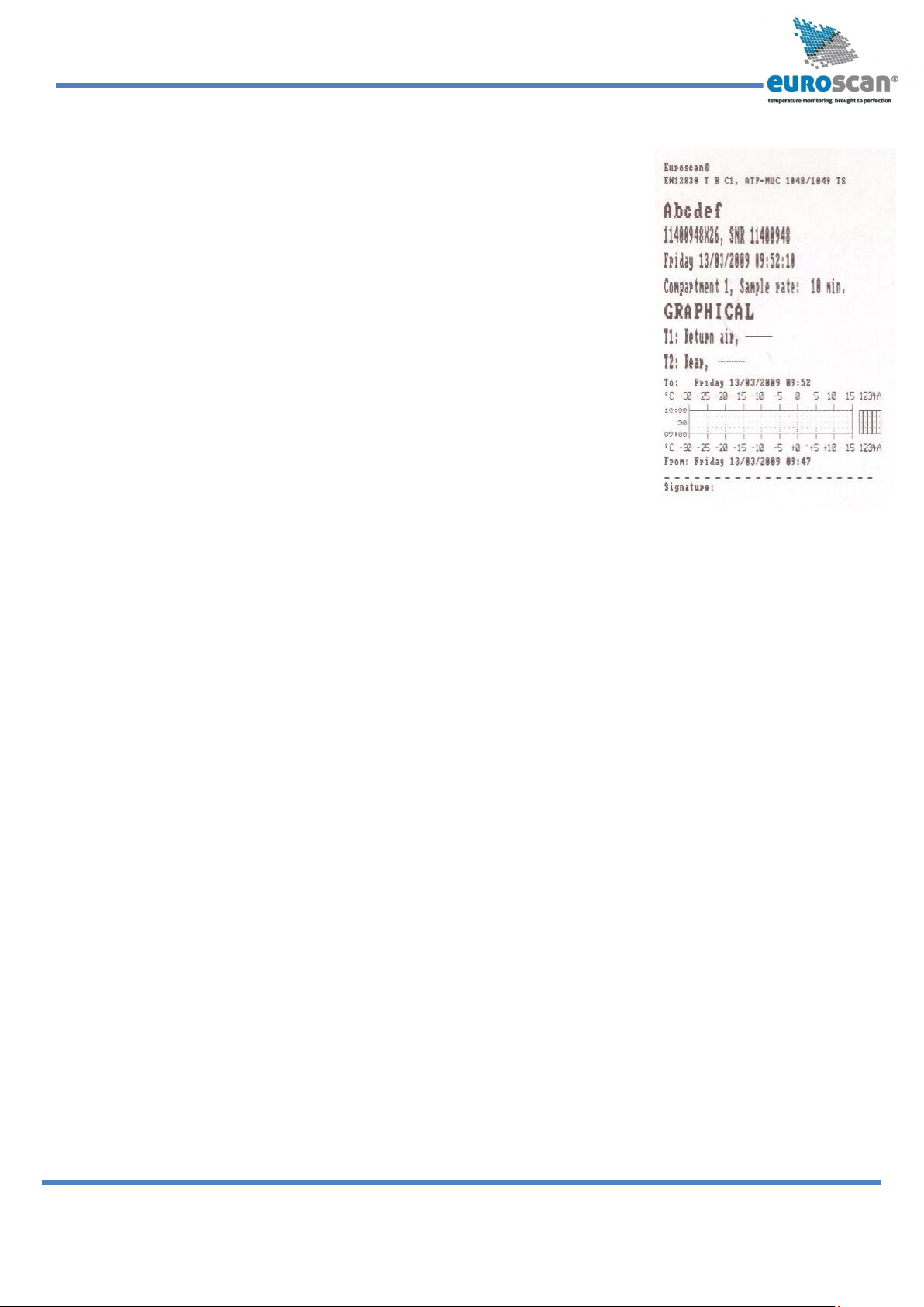
EUROSCAN RX2-6/TX2-6 can provide evidence of correct temperatures for every trip in the form of a
delivery ticket, numerical or graphical print-out. All data is stored with a date/time stamp in a large flash
memory. Data will not be lost if power supply is disconnected. The real time clock is powered by an internal
back-up battery.
Both products are produced by Euroscan in the EU. Euroscan has a policy of continuous development and
improvements. Therefore, products, manuals and technical information are subject to change without prior
notice.
Data security
Although the Euroscan X2-6 recorder has be 0en specifically designed and tested for use in the harsh
vehicle environment there are certain circumstances beyond our control, i.e. lightning strikes, high voltage
peaks, theft, manipulation, etc., where data loss could occur. Because the temperature data might be
crucial to providing evidence in the case of transport damages, we strongly advise you to take the following
precautions:
•Print or download data to a PC on a weekly basis as a back-up.
•For a long-term storage of the data, we recommend to download the data into the Euroscan
EuroLOG software via one of the communication options offered by Euroscan. In addition to the
infrared connection, Euroscan offers a variety of communication options for automated data
transfer from the recorder to the different Euroscan software options. For further information
please contact the Euroscan Sales team or visit our website at www.euroscangroup.com.
•Check the correct functioning of the recorder frequently (minimum – together with the fridge
service).
•Check the recording system every 12 months to see if the measurement is within the legal error
limit. The annual test is obligatory, according to resp. EN 12830 or EN 13486.
•Do not weld without disconnecting the power from the Euroscan recorder or the vehicle.
•Do not take the power supply from a generator system without extra filter protection against high
voltage peaks. Preferably, always take power direct from the vehicle or fridge battery.
•Follow the installation and user instructions.

EUROSCAN RX2-6 / TX2-6
USER MANUAL
EN-MAN-0042.02
5 of 28
Mai 15, 2014
To navigate through the menus and to select in the edit mode a parameter from a table, use the
buttons as described below:
Blue
↑
Previous item of the menu
< In edit mode: previous item from the list
Yellow
↓
Next item of the menu
> In edit mode: next item from the list
Green edit Menu select, change to edit mode or one menu level down
accept In edit mode: accept input and go to next menu point
Red <-Menu One menu level up
<-Cncl In edit mode: cancel input and display the non-changed value.
Press 2 seconds for rejecting input and return to previous menu.
When entering free programmable text like names the button functions are as follows:
Blue
↑
Next character from the list
Yellow
↓
Previous character from the list
Green < One character to the left
Red > One character to the right
Blue + Yellow <-cncl Cancel input and display the non-changed value.
Press for 2 seconds to reject the input and go back to the
previous menu.
Green + Red accept Accept input and go to next menu point.
EUROSCAN RX2-6/TX2-6 has four different user menus which are accessible via the keyboard without
PIN code:
•Print menu
•Alarm menu
•User settings menu
•Status menu

EUROSCAN RX2-6 / TX2-6
USER MANUAL
EN-MAN-0042.02
6 of 28
Mai 15, 2014
1.1 Select compart-
ment to print
(Compartment 1)
↑↓EDIT <-MENU
1.2 Time zone offset
for printing
(0 hour(s))
↑↓EDIT <-MENU
Delivery ticket
CURRENT VALUES
<-CNCL
1.4 Print report
PARAMETERS
↑↓ACCEPT <-MENU
1.5 Set print date
↑↓EDIT <-MENU
1.6 Delivery ticket
settings
↑↓EDIT <-MENU
1.3 Print report
EVENTS
↑↓ACCEPT <-MENU
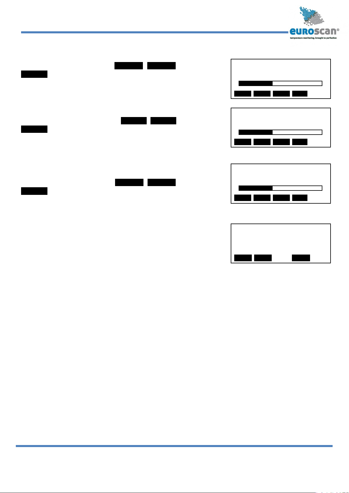
Menu 1 Print menu
Press the blue button. The last selected print choice will be displayed.
Printing now starts after 2 seconds. Repeatedly pressing the blue
button will scroll between the available print options: delivery ticket,
journey ticket graphical, journey ticket, numerical, and historical ticket.
By pressing the blue button for more than 2 seconds the following sub-menus are reached:
1.1 Select compartment to print
By pressing the green button you confirm that you wish to change the
settings. The chosen compartment can be selected by pressing <
>and your choice can be confirmed with ACCEPT
1.2 Time zone offset for printing
This option is intended to have the local time printed on your ticket. In
case “0 hour(s)” is selected, the recorder time will be printed.
1.3 Print event report
When pressing the green button/ ACCEPT printing of the event report
will start.
1.4 Print parameter report
By pressing the green button/ ACCEPT, the parameter report will be
printed after entering the correct pin code (1-2-1-2).
1.5 Set print date
With EDIT you can select a historical date for printing. After you
pushed ACCEPT you can select the required report with the blue
button. Printing starts after a delay of 2 seconds.
1.6 Delivery ticket settings
With EDIT you can set the desired information printed on the
delivery ticket. You can select “actual value”, “actual + average” or
“actual, average and min-max values”. By pressing the green button
you ACCEPT your choice.

EUROSCAN RX2-6 / TX2-6
USER MANUAL
EN-MAN-0042.02
7 of 28
Mai 15, 2014
1.7 Print time period
(10 hour(s))
↑
↓
EDIT <-MENU
1.8 Day start time
( 0:00)
↑↓EDIT <-MENU
1.9 Day end time
(18:00)
↑↓EDIT <-MENU
JOURNEY START
Print marker set
1.7 Print time period
With this option you define the total print period.
1.8 Day start time
This option defines the time which is taken as start time for the
printout (printout is printed backwards until this time).
1.9 Day end time
This option defines the time from which the printout is printed
backwards (please note that a printout is always printed backwards,
i.e. from the day end time till start time).
Examples:
−You want to make a printout for a certain date in the past for a time
period which exceeds the day start time. Please change day start time
to 0:00 h and enter the desired time period.
−You want to make a printout for 2 days. Change time period to 2 days, day start time to 0:00 h - day end
time to 0:00 h.
−By pressing the YELLOW key for more than 3 seconds you define a
starting point for a dedicated journey. The display will show this.
Printing will start from the defined journey start.

EUROSCAN RX2-6 / TX2-6
USER MANUAL
EN-MAN-0042.02
8 of 28
Mai 15, 2014
Alarms
Comp 1 Comp 2
OFF OFF
XX XX X
2.1 Compartment 1
(Off)
↑↓EDIT <-MENU
2.1 Compartment 1
Frozen
< >ACCEPT <-CNCL
Menu 2 Alarm settings
Up to four different alarm types can be allocated to up to four different
compartments. The various alarms (and compartments) are only
available if the supervisor has preset and configured them in the
parameter menu.
Digital input 1 and 2: When not enabled as digitals, they are used for switching on and off the alarm
compartments 1 and 2. The driver is able to select either compartment, followed
by: OFF / last alarm setting
Press the YELLOW button to access the alarm menu.
2.1 Compartment 1
When pressing the yellow button a second time you reach the options
which can be changed. With
↑
↓
you toggle between
the compartments available. The value given in brackets shows the
actual setting. By pressing EDIT you can change alarms for the
selected compartment.
With < >you select the desired alarm type (including
alarm off). By pressing ACCEPT the new setting will be activated. The
display now changes to the next menu entry.
2.2 Compartment 2 (same as Compartment 1)
2.3 Compartment 3 (same as Compartment 1)
2.4 Compartment 4 (same as Compartment 1)
2.5 Digital input 1
The Euroscan X2-6 recorders are provided with 4 digital inputs that can be used for invoking alarms from
door switches and refrigerators. An alarm condition is reached if an input remains in an alarm condition for
a certain period of time. This preset (delay time) can be up to 60 minutes.
2.6 Digital input 2 (same as Digital input 1)
2.7 Digital input 3 (same as Digital input 1)
2.8 Digital input 4 (same as Digital input 1)
2.9 Alarm output test
Pressing the green key TEST will initiate the external alarm for 10 seconds. This may be a light or buzzer connected to
the recorder.

EUROSCAN RX2-6 / TX2-6
USER MANUAL
EN-MAN-0042.02
9 of 28
Mai 15, 2014
3.1 Set time
(14:00:31)
↑
↓
EDIT <-MENU
3.1 Set time
14:00:31
< - cncl ` accept
↑
↓
<>
3.2 Sum/Wint corr.
(Auto. adjustment)
↑↓EDIT <-MENU
3.3 Set date
18/02/2008
< - cncl ` accept
↑↓<>
3.4 Select language
(English)
< >ACCEPT <-CNCL
Menu 3 User settings menu
With the user settings, several adjustments can be made to offer the
user a maximum of user convenience. By pressing the green button
the user setting menu will be activated.
Toggle with
↑
↓
between the available menu options
(3.1 to 3.2, 3.3, …). Between brackets (..) the actual setting is
displayed.
With EDIT you enter the edit mode. In this menu you can change the settings at your convenience. The
supervisor PINCODE, factory set at, 1111, is required. The following pictures show the display in the edit
mode.
3.1 Set time
Select hours, minutes, and seconds with < > and adjust
with
↑
↓
. Confirm the setting with ACCEPT (green-
red).
3.2 Summer/Winter time correction
If you do not want an automatic adjustment of summer and winter time
you could define this here. The supervisor PINCODE, is required.
3.3 Set date
Select date, month, and year with < >and adjust with
< >. Confirm setting with ACCEPT (green-red
simultaneously). The supervisor PINCODE is required.
3.4 Select language
Select the desired language with < >and confirm with
ACCEPT.
3.5 Set display contrast
Set the desired display contrast < >
and confirm with
ACCEPT.
3.6 Set display backlight
Set the intensity of the backlight to your convenience
< >and confirm with ACCEPT. The light switches on
when you press any button and switches off after 30 seconds.
3.5 Set display
contrast
< >ACCEPT <-CNCL
3.6 Set display
backlight
< >ACCEPT <-CNCL
EUROSCAN RX2-6 / TX2-6
USER MANUAL
EN-MAN-0042.02
10 of 28
Mai 15, 2014
TMS X2 V2.086
© 11/02/2009 11:01
↑↓<-MENU
3.7 Set buzzer volume
Change the buzzer volume with < >and confirm with
ACCEPT. This only applies to key presses, and not to alarms.
3.8 Set buzzer frequency
Change the buzzer frequency with < >and confirm with
ACCEPT. This only applies to key presses, and not to alarms.
3.9 Set buzzer on-time
Change the buzzer on-time with < >and confirm with
ACCEPT. This only applies to key presses, and not to alarms.
3.x TMS X2 V2.08
Displays the actual firmware version of the recorder.
3.7 Set buzzer
volume
< >ACCEPT <-CNCL
3.8 Set buzzer
frequency
< >ACCEPT <-CNCL
3.9 Set buzzer
on-time
< >ACCEPT <-CNCL

EUROSCAN RX2-6 / TX2-6
USER MANUAL
EN-MAN-0042.02
11 of 28
Mai 15, 2014
T1 11.2 T2 20.0
T3 -12.3 T4 -3.8
T5 -18.7 T6 OC
Parameter Settings
ENTER PINCODE
-1- -2- -3- -4-
Menu 4 Status menu
Press red button. The display mode will change between full menu
information, or only showing actual temperatures enlarged and
reading to one decimal point. Used when carrying out verification
procedure.
In order to return to the main display please press any button.
4.x Parameter menu
The EUROSCAN TX2-6/RX2-6 recorder has been designed to enable
a multiple number of desired applications for individual customers. By
using the corresponding parameter settings you can adjust the
recorder functionality to the required needs. This chapter gives an
overview and structure of the various parameters available.
To enter the parameter menu press the green button for 2 seconds. The display will show: “ENTER
PINCODE”.
The default setting of the pin code is 1111, but can be adjusted by the supervisor at any time (ask your
distributor).
After entering the correct pin code you have access to the parameter menu and the first menu level is
displayed. Select the desired item with [↑], [↓] and press [EDIT] to enter one of the following options:
5 Temperature inputs settings
6 Digital inputs settings
7 Compartment settings
8 Alarm settings
9 Printer settings
10 General settings
11 Communication settings
A 4 digit PIN code has to be entered in order to enter menus 5 to 11.

EUROSCAN RX2-6 / TX2-6
USER MANUAL
EN-MAN-0042.02
12 of 28
Mai 15, 2014
5 Temperature inp.
settings
↑↓EDIT <-MENU
5.1.3 Name
“Free text”
< - cncl ` accept
↑
↓
<>
Menu 5 Temperature input settings
Inputs for temperature measurements can be switched on/off and assigned a name, depending
on the sensor position. Default, input 1 is preset as ‘Return air’ and input 2 as ‘Rear’.
5.1 T1 input > On/Off
If „on“ input 1 will be measured, displayed and stored into
memory. Printing of input 1 is assigned in the compartment
setting (menu item 7). When ‘Off’, go to item 5.2.
5.1.1 Type > Temperature
You can select a sensor type (temperature or relative humidity)
Temperature input
Relative Humidity input (0..1 V)
Universal input (0..2,5 V)
Current sensor input (4..20 mA)
External sensor (see Doc. No. EN-209-4:UD External analogue and digital sensors protocol)
5.1.2 Name (sensor) > Return air
You can select a sensor name from the table or enter a free text (free text is not translated
when the language is changed !!!)
5.1.3 Name (free text) > free text
Enter a text as desired via the four buttons
5.2 T2 input > on/off, menu structure as 5.1
5.3 T3 input > on/off, menu structure as 5.1
5.4 T4 input > on/off, menu structure as 5.1
5.5 T5 input > on/off, menu structure as 5.1
5.6 T6 input > on/off, menu structure as 5.1

EUROSCAN RX2-6 / TX2-6
USER MANUAL
EN-MAN-0042.02
13 of 28
Mai 15, 2014
6 Digital inputs settings
↑
↓
EDIT <-MENU
Menu 6 Digital inputs settings
4 inputs for status recording, all inputs can be switched on/off, assigned
with a name and inverted polarity. Some names are available as a factory
setting and can be selected from a list.
In the operating mode you can see on the display which inputs are
activated. A small rectangle indicates that the input is active and the
status “low”. When the status is “high”, depending on the assigned
function, a corresponding symbol is displayed:-
�= Defrost inactive
= Defrost active
�= Refrigeration inactive
= Refrigeration active
| = Back door / Side door closed
= Back door / Side door open
= Battery back-up active/low charge – the recorder is working on normal power
= Battery back-up active/high charge – the recorder is working on backup battery
= Free text active
= Free text inactive
6.1 Digital input 1 > On/Off
If ”on“, every input status change on D1 will be displayed and recorded with a date/time stamp.
6.1.1 Name > Refrigeration
Select a sensor name from the list or enter a free text (free text is not translated when changing
the language).
6.1.3 Active > high/low
Input polarity switch. Switch function if “high”: contact closed = input active. If “low”: contact open
= input active (applicable for door contacts, active = open)
6.1.4 Alarm > On/Off
ON in order to activate alarm for this input. In this case you get the following options:
6.1.4.1 Delay time > 10 minute(s)
Alarm delay time given in minutes

EUROSCAN RX2-6 / TX2-6
USER MANUAL
EN-MAN-0042.02
14 of 28
Mai 15, 2014
6.1.4.3 Store position when alarm active > Yes/No
Here, the GPS position at the moment of the ALARM can be stored.
6.1.5 Store position when input active/inactive or both
> NO
> WHEN INPUT ACTIVE
> WHEN INPUT INACTIVE
> WHEN ACTIVE + INACTIVE
6.2 Digital input 2 > On/Off, menu structure as 6.1
6.3 Digital input 3 > On/Off, menu structure as 6.1
6.4 Digital input 4 > On/Off, menu structure as 6.1

EUROSCAN RX2-6 / TX2-6
USER MANUAL
EN-MAN-0042.02
15 of 28
Mai 15, 2014
Menu 7 Compartment settings
In this menu you have to configure the print and alarm functions for up to maximum 4 compartments. Per
compartment, one name can be assigned like FRONT, BACK, SIDE. The user is able to print a ticket or
activate an alarm per compartment.
7.1 Compartment 1 >On/Off
Activates or deactivates compartment 1
7.1.1 Compartment name > (compartment 1)
The compartment name has to be set as a free text and will not be translated when changing
the language
7.1.2 Print T1 > Yes/No
Choose whether T1 should be printed or not
7.1.3 Alarm on T1 > Yes/No
Choose whether T1 can invoke an alarm or not
7.1.3.1 Store position when alarm active > Yes/No
The GPS position of the vehicle can be stored in case the alarm changes from Inactive to active.
7.1.3.2 Store position when alarm inactive > Yes/No
The GPS position of the vehicle can be stored in case the alarm changes from active to Inactive.
7.1.4 Print T2 > Yes/No
Same as T1
7.1.5 Alarm on T2 > Yes/No
Same as T1
7.1.5.1 Store position when alarm T2 active > Yes/No
Same as T1
7.1.5.2 Store position when alarm T2 inactive > Yes/No
Same as T1
7.1.6 Print T3 > Yes/No
Same as T1
7.1.7 Alarm on T3 > Yes/No
Same as T1
7.1.7.1 Store position when alarm T3 active > Yes/No
Same as T1
7.1.7.2 Store position when alarm T3 inactive > Yes/No
Same as T1

EUROSCAN RX2-6 / TX2-6
USER MANUAL
EN-MAN-0042.02
16 of 28
Mai 15, 2014
7.1.8 Print T4 > Yes/No
Same as T1
7.1.9 Alarm on T4 > Yes/No
Same as T1
7.1.9.1 Store position when alarm T4 active > Yes/No
Same as T1
7.1.9.2 Store position when alarm T4 inactive > Yes/No
Same as T1
7.1.10 Print T5 > Yes/No
Same as T1
7.1.11 Alarm on T5 > Yes/No
Same as T1
7.1.11.1 Store position when alarm T5 active > Yes/No
Same as T1
7.1.11.2 Store position when alarm T5 inactive > Yes/No
Same as T1
7.1.12 Print T6 > Yes/No
Same as T1
7.1.13 Alarm on T6 > Yes/No
Same as T1
7.1.13.1 Store position when alarm T6 active > Yes/No
Same as T1
7.1.13.2 Store position when alarm T6 inactive > Yes/No
Same as T1
7.1.14 Store position on COMPARTMENT ALARM >NO
>WHEN SWITCHED ON
>WHEN SWITCHED OFF
>WHEN SWITCHED ON + OFF
7.1.15 Print D1 > On/Off
7.1.16 Print D2 > On/Off
7.1.17 Print D3 > On/Off
7.1.18 Print D4 > On/Off
7.2 Compartment 2, 3 and 4 > On/Off, menu structure as menu 7.1

EUROSCAN RX2-6 / TX2-6
USER MANUAL
EN-MAN-0042.02
17 of 28
Mai 15, 2014
Menu 8 Alarm settings
There are 4 alarm groups – each with a name to assign, upper and lower temperature limit and a delay
time. Each enabled alarm type can be activated by the user for any compartment, although per
compartment only one alarm group can be set at the same time.
8.1 Alarm Group 1 > On/Off
8.1.1 Name >Frozen
You can select a pre-set alarm group from a list or enter a free text (free text is not translated
when changing the language).
8.1.3 Temperature upper limit > +50 °C
VALID WHEN INPUT IS A TEMPERATURE
8.1.4 Temperature lower limit > -30 °C INPUT (SEE 5.1.1)
8.1.5 % upper limit > 0..100%
VALID WHEN INPUT IS A RELATIVE HUMIDITY,
8.1.6 % lower limit > 0..100% UNIVERSAL OR CURRENT SENSOR (SEE 5.1.1)
8.1.7 Initial Delay time > 120 min.
This is the time before an alarm condition will be considered as a ‘real alarm’ (intended to ignore
alarms, e.g. in case the refrigerator has started and the compartments have not yet reached
their set point temperature).
8.1.8 Delay time > 60 min.
This is the time that an alarm condition has to be ‘true’, before an alarm will be evoked.
8.2 Alarm Group 2 > On/Off, menu structure as menu 8.1
8.3 Alarm Group 3 > On/Off, menu structure as menu 8.1
8.4 Alarm Group 4 > On/Off, menu structure as menu 8.1
8.5 ALARM BEHIND PIN
Option to make the alarm settings accessible by entering a PIN code.
8.6 OUTPUT FUNCTION
Define the function of the alarm output (AO) on CON1: alarm output or remote on/off.
By choosing “remote on/off”, the output can remotely be handled over a GPRS connection.

EUROSCAN RX2-6 / TX2-6
USER MANUAL
EN-MAN-0042.02
18 of 28
Mai 15, 2014
8.7 alarm repetitions
Defines the number of times an alarm output (buzzer and alarm output) should be repeated after it has
been acknowledged by the yellow button or timed out due to the ‘Alarm output time span’. Selecting ‘0’ will
disable alarm repetition and the maximum number is 10.
8.7.1 Interval of alarm repetitions
Defines the time in minutes before repeating an alarm, what has been acknowledged or has timed out.
Minimum interval time is 1 and maximum is 60 minutes.
8.7.2 Alarm output time span
Often the alarm output is used to control an external acoustic alarm. To avoid noise pollution and to comply
with legal requirements the alarm output time can be controlled by this parameter:
•‘0’= Alarm output will stay active until the alarm is acknowledged by the yellow button or if the
alarm conditions do no longer apply.
•‘1-240’ minutes; Alarm output will stay active until the alarm is acknowledged by the yellow button
or if the programmed time has been reached.
EUROSCAN RX2-6 / TX2-6
USER MANUAL
EN-MAN-0042.02
19 of 28
Mai 15, 2014
Menu 9 Printer settings
Following settings enable you to configure the printer functions as desired:
9.1 Graph upper limit > +50 °C
Upper limit for graphical printout
9.2 Graph lower limit > -30 °C
Lower limit for graphical printout
Note: If the total temperature range between upper
and lower limit can be divided by 9 you achieve an
optimal result for the printout
9.3 Graph mm per hour > 10 mm
A graphical printout consumes a lot of paper. This parameter
enables you to set the scaling of the printout (mm of paper per
hour). Set a value to avoid wasting paper.
9.4 User menu > Yes/No
If set to ‘Yes’, the following 4 parameters will be available for the user in the print menu (see chapter
3.1 for detailed description).
9.5 Delivery ticket setting
Print [Actual only], [Actual + average] or [Actual + average + min/max] temperature.
9.6 Print time period > 10 hours
Set time period (explained in chapter 1.6)
9.7 Day start time > 06:00
Set day start time for printing (explained in chapter 1.7)
9.8 Day end time > 18:00
Set day end time (explained in chapter 1.8)
This manual suits for next models
1
Table of contents
Popular Measuring Instrument manuals by other brands

Tecfluid
Tecfluid M21 instruction manual

Ecom
Ecom J2KNpro Tech operating instructions

Topex
Topex 94W120 instruction manual

EUTECH INSTRUMENTS
EUTECH INSTRUMENTS CYBERSCAN TB 1000 TURBIDITY METER instruction manual

Seitron
Seitron NOVO Use and maintenance

Observint
Observint ALIBI ALI-QVR5116H Quick setup guide


Anritsu
Anritsu VectorStar ME7848A-0272 Maintenance manual

DYNAPAR
DYNAPAR NorthStar RIM Tach 1250 instruction manual

Heska
Heska Element DC manual

Precision Digital Corporation
Precision Digital Corporation PD6801-0K1-M20 instruction manual

Endress+Hauser
Endress+Hauser mini-log b operating instructions

Bushnell
Bushnell Sport 202201 instruction manual