Eurospec XIA5003 User manual

XIA5003 External Locking
Attachment Instructions
FITCB0087 | Revision A
+44 1228 511030
Carlisle Brass Ltd, Parkhouse Road, Carlisle, CA3 0JU
www.carlislebrass.com
Installation and Operating Instructions
External Locking Attachment
Important Information
This product is designed to operate with Eurospec Emergency and Panic Exit Devices XIA5002,
and XDL5760, which are tted to comply with EN179 or EN1125
This product is non-handed and can be tted on both left and right handed doors.
With the External Locking attachment in “Unlocked” position, pull handle to release XIA5002
Push Pad Device.
Lock and unlock External Locking Device as follows:
“Unlocked” position - Insert key, turn clockwise to stop, turn key back to starting position, and
withdraw key.
“Locked” position - Insert key, turn anti-clockwise to stop, turn key back to starting point, and
withdraw key.
Note: The key must always be removed prior to operation.
With external Locking Attachment in “locked” position, handle wth pull, but the follower will not
rotate.
After 20,000 operations, lubricate using GT85 PTFE solution or similar. Repeat after each
additional 20,000 operations.
Ensure all xings are secure, and check for correct operation.
PLEASE READ THESE INSTRUCTIONS CAREFULLY
Operational Instructions and Maintenace
Page 1 of 6
XIA5003 External Locking
Attachment Instructions
FITCB0087 | Revision A
+44 1228 511030
Carlisle Brass Ltd, Parkhouse Road, Carlisle, CA3 0JU
www.carlislebrass.com
Product Preparation
Prior to tting, select correct hand of door, See Fit. 1 and prepare spindle roation as follows:
Right Hand door, rotate follower fully “clockwise.” See Fig. 2
Left Hand door, rotate follower rully “anti-clockwise.” See Fig. 2
Installation
Fig. 1 Fig. 2
Follower
Step 1. Fitting with Push Pad
1.1 Referring to the dimensions shown
in Fig. 3, drill the 3 xing holes and
20mm spindle hole.
1.2 Cut spindle to the correct length to
suit the door thickness and insert into
the External Locking Attachment.
1.3 Fit the External Locking Attachment
to the door, ensuring that the top and
bottom xing screws pass through
the Push Pad back plate. See Fig. 4
1.4 Fit the Push Pad According to Push
Pad tting Instructions.
Fig. 3
Fig. 4
Page 2 of 6

XIA5003 External Locking
Attachment Instructions
FITCB0087 | Revision A FITCB0087 | Revision A
+44 1228 511030
Carlisle Brass Ltd, Parkhouse Road, Carlisle, CA3 0JU
www.carlislebrass.com
PLEASE LEAVE THESE INSTRUCTIONS WITH THE END USER
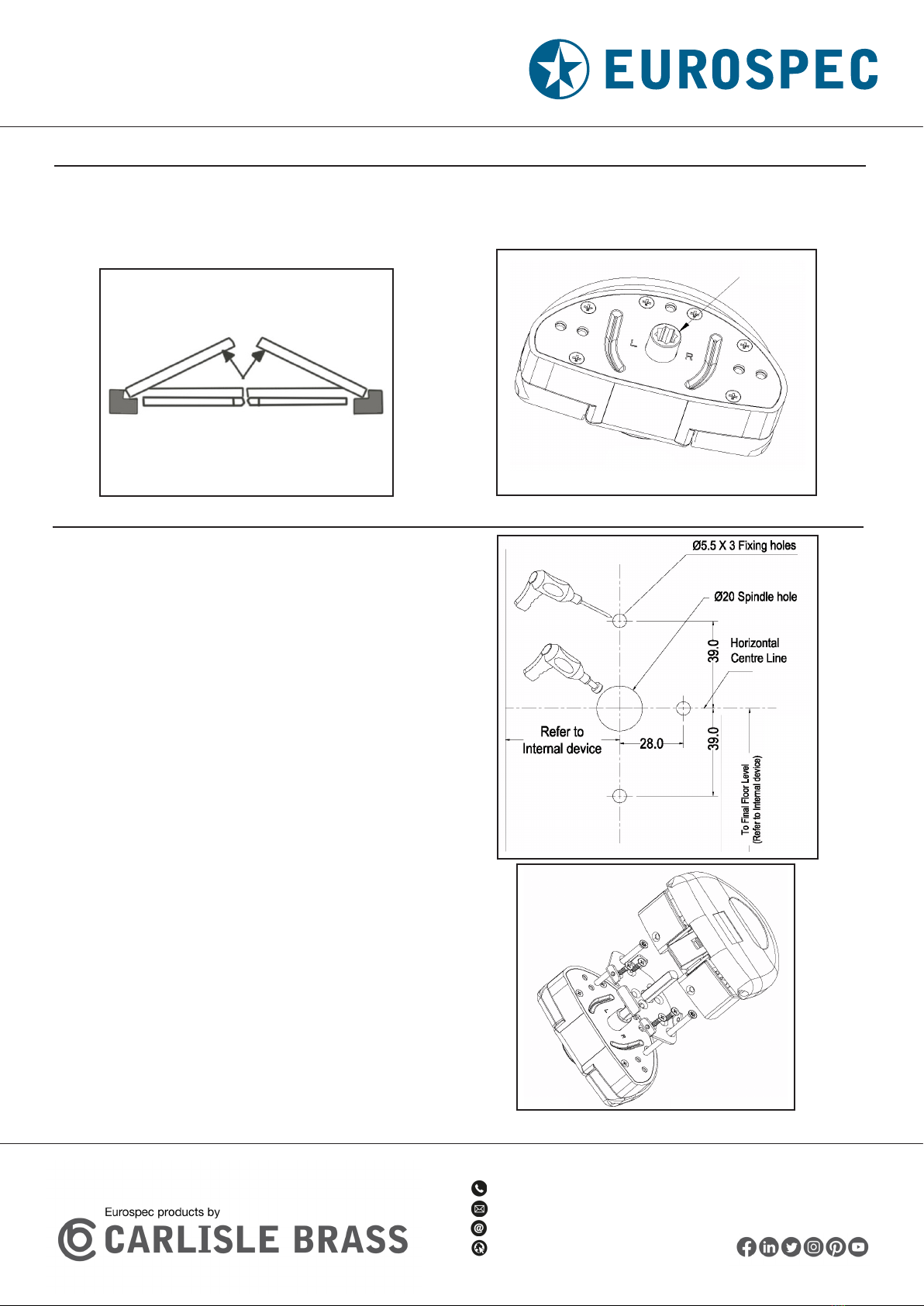
Installation With XDL5760 Push Bar Panic Latch
Step 1. Fitting with Push Pad
3.1 Ensuring the Follower centreline of External
Locking Attachment is aligned with Follower
centreline of the internal devicce, drill 3 x
5.5mm diameter holes for xing bolts and 1
hole for spindle. The spindle hole size can vary
depending upon device used. See Fig. 5 for
guidance. All measurments are in mm.
3.2 Check the starting position and working
rotation of the follower is correct for the hand of
door.
3.3 Cut the spindle to the correct length to suit
the door thickness.
3.4 Secure external Locking Attachment to the
door. A selection of xing bolts are supplied to
suit different applications and door thicknesses.
3.5 Fit the internal easy-exit device according to
the relevent tting isntructions.
Fig. 5
Page 3 of 6

XIA5003 External Locking
Attachment Instructions
FITCB0087 | Revision A
+44 1228 511030
Carlisle Brass Ltd, Parkhouse Road, Carlisle, CA3 0JU
www.carlislebrass.com
Annex A
Installation and Fitting Instructions
A.1 The producer shall specify the appropiate xing arrangement for the door types for which the
exit device is designed.
A.2 Before tting an exit device to a door, the door should be checked to ensure correct
hanging and freedom from blinding. It is not recommended, for example, that exit devices be
tted to hollow core doors unless specially designed by the producer for this type of door. It is
recommended to verify that the door construction allows the use of the device, i.e. to verify that
offset hinges and engaging leaves allow both leaves to be opened simultaneously (See A4), or
to verify that the gap between door leaves does not differ from that dened by the exit device
producer, or to verify that the opening elements do not interfere, etc.
A.3 Before tting an emergency exit device to a re/smoke resisting door, the re certication of
the re door assembly on which the exit device has been tested to prove suitability for use on a
re door should be examined. It is of utmost importance that an exit device is not used on a re
door assembly of a greater re resistance time than approved for. See Annex B.
A.4 Care should be taken to ensure that any seals or weather-stripping tted to the complete
door assembly, do not inhibit the correct operation of the emergency exit device.
A.5 On double doorsets with rebated meeting stiles and where both leaves are tted with
emergency exit devices, it is essential to check that either leaf will open when its emergency exit
device is activated and also that both leaves will open freely when both emergency exit devices
are operated simultaneously.
A.6 Where emergency exit devices are manufactured in more than one size, it is important that
the correct size is selected.
A.7 Category 2 (Standard projection) emergency exit devices should be used in situations where
there is restricted width for escape, or where the doors to be tted with the emergency exit
devices are not able to open beyond 90°
A.8 Where an emergency exit device is designed to betted to a glazed door, it is essential that
the glazing is tempered or laminated glass.
A.9 Different xing can be necessary for tting emergency exit devices to wood, metal
or frameless glass doors. For more secure xing, male and female through-door bolts,
reinforcement and rivets can be used.
Page 4 of 6

XIA5003 External Locking
Attachment Instructions
FITCB0087 | Revision A FITCB0087 | Revision A
+44 1228 511030
Carlisle Brass Ltd, Parkhouse Road, Carlisle, CA3 0JU
www.carlislebrass.com
A.10 Emergency exit devices are not intended for use on double action (double swing) doors
unless specically designed by the exit device producer.
A.11 The xing instructions should be carefully followed during installation. These instructions
and any maintenance instructions should be passed on by the installer to the user. See Annex C
A.12 The operating element should normally be installed at a height of between 900mm and
1100mm from the nished oor level, when the door is in the secured position. Where it is known
that the majority of the users of the premises will be young children, consideration should be
given to reducing the height of the operating element.
A.13 When installing lever operating emergency exit devices, particularly on doors with raised or
recessed surfaces, consideration should be given to minimizing any potential safety risks, such
as the trapping of ngers or clothing.
A.14 The bolt heads and keepers should be tted to provide secure engagement. Care should be
taken to ensure that no projection of the bolt heads, when in the withdrawn position, can prevent
the door swinging freely.
A.15 Where emergency exit devices are to be tted to double door sets with rebated meeting
stiles and self closing devices, a door coordinator device in accordance with EN 1158 (See
Bibliography) should be tted to ensure the correct closing sequence of the doors. This
recommendation is particularly important with regard to smoke/re-resisting door assemblies.
A.16 No devices for securing the door in the closed position should be tted other than specied
in this European Standard. This does not preclude the installation of self-closing devices.
A.17 If a door closing device is to be used to return the door to the closed position, care should
be taken not to impair the use of the doorway by the young, elderly and inrm.
A.18 Any keepers or protection plates provided should be tted in order to ensure compliance
with this European Standard.
A.19 A sign which reads “Rotate handle to open” or “Push to open” as appropriate, or a
pictogram should be provided on the inside face of the door immediately above the operating
element or on the operating element if it has a sufcient at face to take the size of lettering
required.
For type “B” emergency exit devices intended for use on inwardly opening exit doors, a sign
which reads “Rotate handle and pull to open” or “Pull to open” or a pictogram should be
provided on the inside face of the door immediately above or on pull pad if it has a sufcient at
face to take the size of lettering required. The surface area of the pictogram should be not less
than 8000mm² and its colours should be white on a green background. It should be designed
such that the arrow points to the operating element, when installed.
Page 5 of 6

XIA5003 External Locking
Attachment Instructions
FITCB0087 | Revision A
+44 1228 511030
Carlisle Brass Ltd, Parkhouse Road, Carlisle, CA3 0JU
www.carlislebrass.com
Annex C
Maintenance Instructions
The following information shall accompany the product:
A) Inspect and operate the emergency exit device to ensure that all components are in a
satisfactory working condition. Using a force gauge, measure and record the operating forces to
release the exit device.
B) Ensure the keeper(s) is (are) free from obstruction.
C) Check that the emergency exit device is lubricated in accordance with the producer’s
instructions.
D) Check that no additional locking devices have been added to the door since its original
installation.
E) Check periodically that all components of the system are still correct in accordance with the
list of approved components originally supplied with the system.
F) Check periodically that the operating element is correctly tightened and, using a force gauge,
measure the operating forces to release the exit device. Check that the operating forces have not
changed signicantly from the operating forces recorded when originally installed.
Page 6 of 6
Table of contents
Other Eurospec Lock manuals

Popular Lock manuals by other brands

Digilock
Digilock Numeris Versa Product guide

OPERTIS
OPERTIS ES7810 operating instructions

Simons Voss Technologies
Simons Voss Technologies MK.CD.STARTER quick guide

Trane
Trane ELECTRONIC MORTISE LOCK owner's guide

INSYS
INSYS CombiLock 200 simplex manual

BQT
BQT YD30M COBALT-mini Installation and operating instructions

Yale
Yale Real Living Assure Lock YRD226 Installation and programming instructions

Sage
Sage Deadbolt Lock troubleshooting guide

Ross
Ross 1000-SERIES operating instructions

LOX
LOX EM5700D installation manual

Safety 1st
Safety 1st HS129 user guide

Olympus Lock
Olympus Lock 720 Series installation instructions


