Eurotech UPPERCUTMANUAL User manual
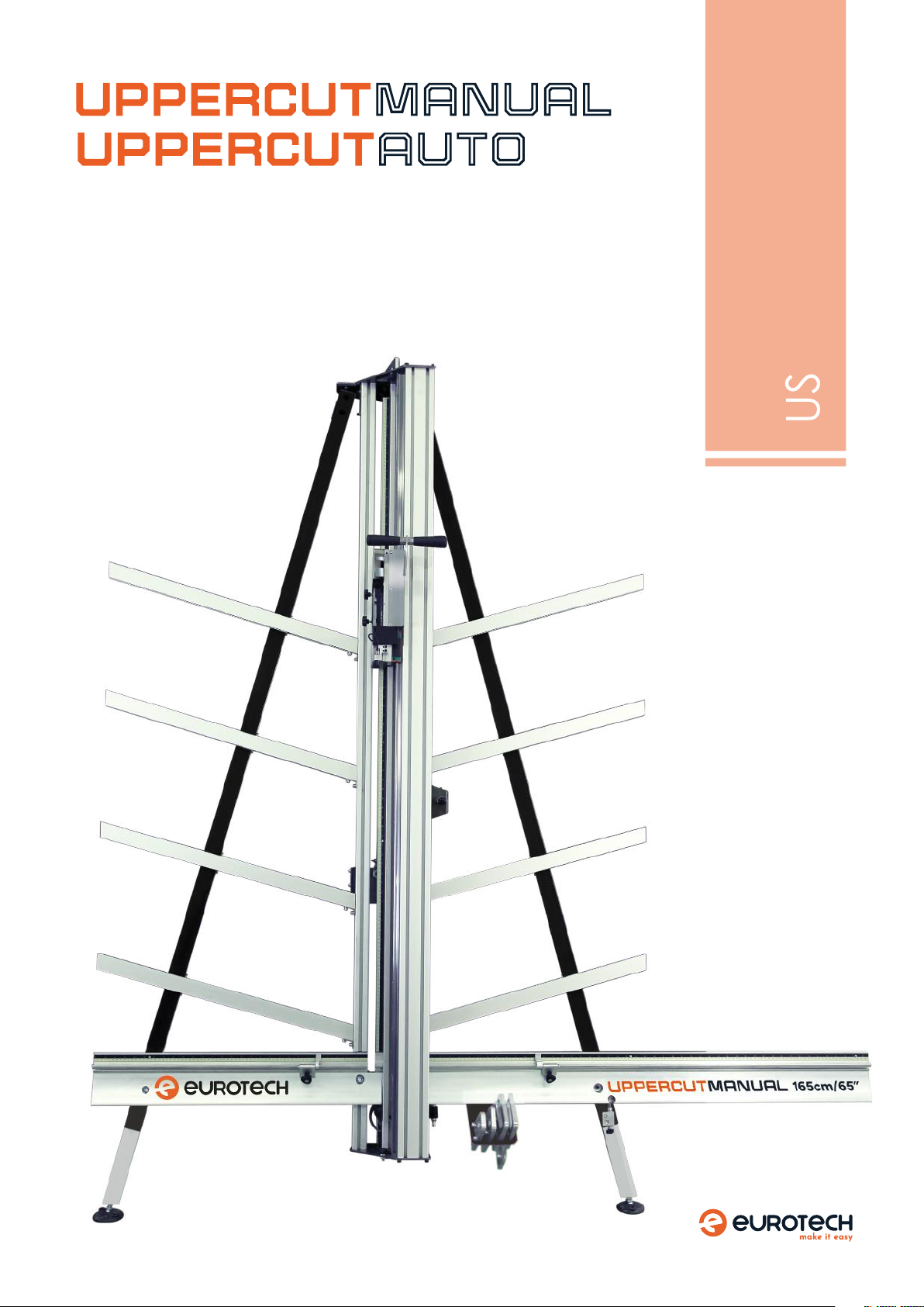
VERTICAL CUTTER
UC-210 UPPERCUT MANUAL VERTICAL CUTTER, 210 cm
UC-250 UPPERCUT MANUAL VERTICAL CUTTER, 250 cm
USERS MANUAL
UC-AUTO-305 UPPERCUT AUTO VERTICAL CUTTER, 305 cm

2
EUROTECH GROUP PTY LTD, 72 John Street, Welshpool 6106, WA

3
INTRODUCTION
EUROTECH is not responsible of damages as result of an use or maintenance of the machine not foreseen in this introduction manual.
In the same way EUROTECH frees any responsibility derived for the use of pieces and spare parts witch are not originals.
This machine has been designed and produced under the essentials requirements of the Directive 98/37 CE.
For any claim or observation, please indicate model, serial number and year, wich is show on the plate, and also the distributor who sold the machine
and address to:
EUROTECH 72 John Street, Welshpool 6106 WA
Tel: +61 1800 30 61 61
Email: [email protected]
INDEX
Introduction.................................................................................................................. 3
General information........................................................................................ 4 - 5
• Machine identication
• Size, weight and package sizes
• How to proceed with transport damages
• Unpacking Instructions
• List of parts
Assembly instructions................................................................................ 6 - 14
Accessories assembly instructions................................................15 - 17
Adjusting the UpperCut..........................................................................18 - 19
• Squaring process
Technical Data .................................................................................................20 - 21
• Technical Characteristics
• Control Device
Uses of the UpperCut .................................................................................22 - 26
Indications....................................................................................................................27
• Uses not allowed
• Security standards
• Maintenance and conservation
• Security signs and vocabulary
Spare parts...................................................................................................................28

4
GENERAL INFORMATION
MACHINE IDENTIFICATION
This machine comes with a dataplate with the following informa-
tion:
CE Marking
Name and address of the manufacturer
Designation of the machine (Model)
Serial number
Weight (kg)
Manufacturing year
All spare orders or technical requests must be accompanied with
model, serial number and purchasing year.
SIZE, WEIGHT AND PACKAGE SIZES
HOW TO PROCEED WITH TRANSPORT DAMAGES
1. Try to open the parcel together with the driver.
2. If the content is damaged, try to make a protocol and pictures
of the damage.
3. If you decide to accept the goods, please do this with writing
“damaged” on the tracking note.
4. Please inform your local importer or dealer about everything
within the very next hours.
UC-210
UpperCut Manual 210 cm
UC-250
UpperCut Manual 250 cm
Dimensions A x B x C 268 x 210 x 56 cm
105 x 82 x 22“
310 x 210 x 56 cm
122 x 82 x 22“
Weight 84 Kg / 185 lb 102 kg / 224 lb
Packing dimensions 278 x 49 x 46 cm 331 x 49 x 46 cm
Packing weight 114 Kg
126 Kg (with free standing)
130 Kg
144 Kg (with free standing)
UC-305
UpperCut Auto 305
Dimensions A x B x C 365 x 210 x 56 cm
143 x 82 x 22 "
Weight 128 Kg / 282 lb
Packing dimensions 410 x 49 x 46 cm
Packing weight 182 Kg
198 Kg (+ free standing)
5
UNPACKING INSTRUCTIONS
The machine comes packed in a cardboard box. It is provided with a working guide and a complementary kit. To unpack the machine, please
follow the next steps:
A. Cut the machine holding strips.
B. Remove the cover of the cardboard box. C. Unscrew and remove the security parts which fix the structure to the cage.
C. Remove all containing groups and parts. Handle with care
CAUTION: Some containing groups and parts into the cage are heavy. Two people are required to manipulate them.
D. Refer to the list of parts and familiarize yourself with all described groups and parts.
E. Read carefully this working guide and see the section “Assembly Instructions” to set up the machine.
GENERAL INFORMATION
LIST OF PARTS INBLADE
Parts to set up the machine:
A1. Main assembly group with lateral brackets UpperCut Manual
A2. Main assembly group with lateral brackets UpperCut Auto
B. Horizontal support group with measurement stops.
C. Panel supports (8 units).
D. Double handle system group Only for UpperCut Manual
E. Adjusting screw system.
F. Cutting heads support.
G. Working guide.
Cutting heads list:
1. Semi-rigids cutting head -Included-
2. Aluminium composite cutting head -Included-
3. Acrylic cutting head -Optional accessory-
4. Triple Blade cutting head -Optional accessory-
5. V-Groove cutting head Rigids -Optional accessory-
6. Re-Board V-Groove Cutting Head -Optional accessory-
7. Foamboard V-Groove Cutting Head -Optional accessory-
8. Glass Cutting Head -Optional accessory-
SET OF ACCESSORIES PROVIDED
Allen keys set (x5).
13 mm wrench.
17 mm wrench.
Tube wrench.
A
1
3
4
5
6 7
2
DEF
C
B
A1 A2
x8
8

6
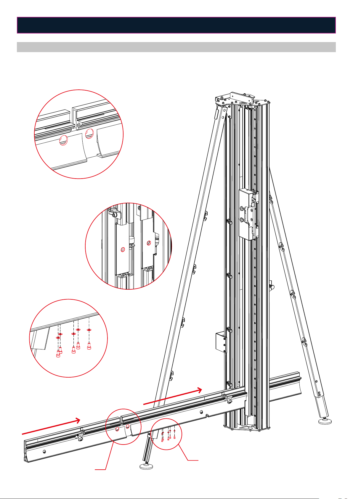
STAGE 1
1. Loosen the top two screws of the lateral bracket located at the left side (A). Repeat the same process for the lateral bracket located at the right side.
2. Open the two lateral brackets until the maximum position (B).
Caution: For the moment do not tighten these four loosened screws.
ASSEMBLY INSTRUCTIONS
B
B
A
Attention: Model shown is the UpperCut Manual but for the UpperCut Auto please follow the same steps.

7
ASSEMBLY INSTRUCTIONS
STAGE 2
1. Loosen the screws which hold the telescopic legs from both sides (A, B).
2. Lengthen the telescopic legs up to the desired length (C). Be sure to put the same length at the right and left side.
3. Tighten the loosened screws to fix the telescopic legs again.
A
B
C
A
B
C
X

8
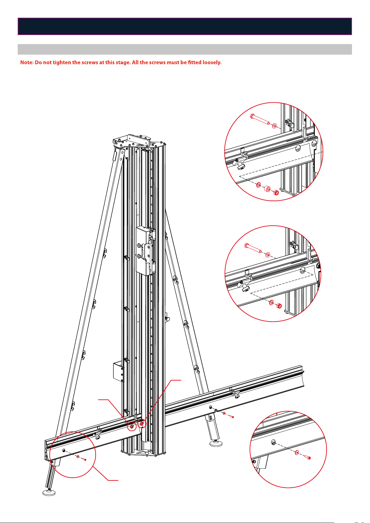
ASSEMBLY INSTRUCTIONS
STAGE 3
1. Remove the screw and the washer from the left lateral bracket (A).
2. Remove the three screws and the washer from the right lateral bracket (B).
3. Remove the screws, washers and nuts from the central columns of the main assembly group (C). Do not remove the two spacers located at the
central columns (D). Caution: Remember the position of all the removed parts.
A
B
C
A
B
C
D
9
ASSEMBLY INSTRUCTIONS
STAGE 4
1. Remove the five screws and the five washers situated at the bottom of the horizontal support group (A).
2. Fit the horizontal support group between the columns of the main assembly group, as shown in the figure. Align the two holes of the horizontal
support group (B) with the two holes of the main assembly group (C).
A
B
A
B
C
10
ASSEMBLY INSTRUCTIONS
STAGE 5
1. Use the screws, washers and nuts removed previously to join the horizontal support group with the main assembly group through the holes of
the central columns (A, B). Use the supplied 17 mm wrenches to fix the nuts.
2. Join the horizontal support group with the two lateral brackets using the screws and washers removed previously (C).
C
A
B
A
B
C

11
ASSEMBLY INSTRUCTIONS
STAGE 6
1. Insert the steel cylinder of the adjusting screw system into the hole of the horizontal support group and next lay and tighten the two screws remo-
ved previously (A).
2. Tighten the screws from the central part of the machine (1, 2) and the screws from the lateral brackets (3, 4) to join strongly the two main assemblies.
Caution: Before tightening, be sure that the two assemblies are well squared.
3. Tighten the screws located at the top of the lateral brackets (B).
A
A
B
1
2
3
4
12
ASSEMBLY INSTRUCTIONS
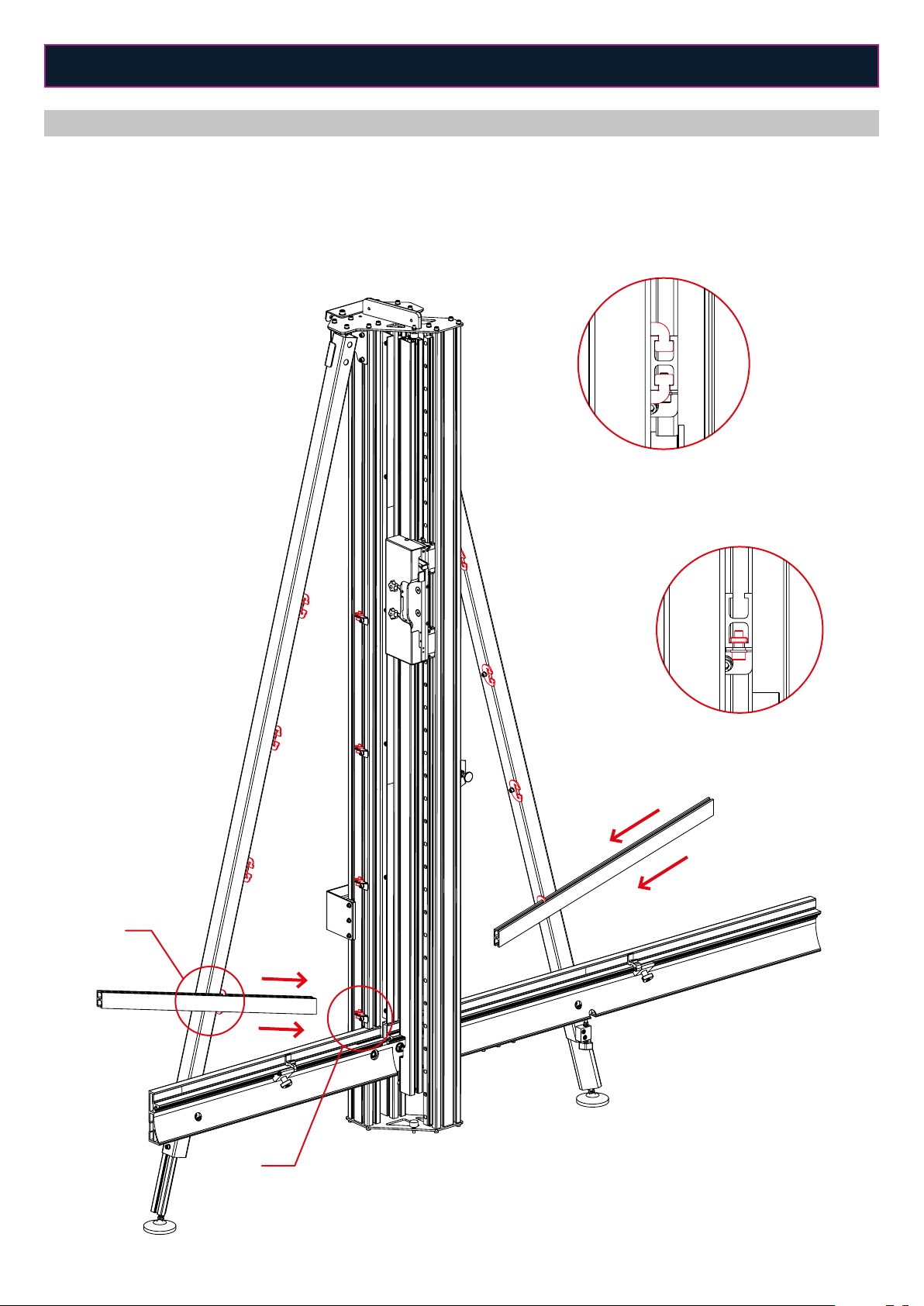
STAGE 7
Note: Stand up the UpperCut and do all the remaining assembly steps vertically.
1. Slide the panel support as shown in the figure and match it with the panel support guide (A).
2. Fit the end of the panel support to the nut located at the central column (B).
3. Fix the panel support by tightening the screw of the nut (B).
4. Repeat the same process to assembly the eight panel supports of the UpperCut.
A
B
A
B
13
ASSEMBLY INSTRUCTIONS
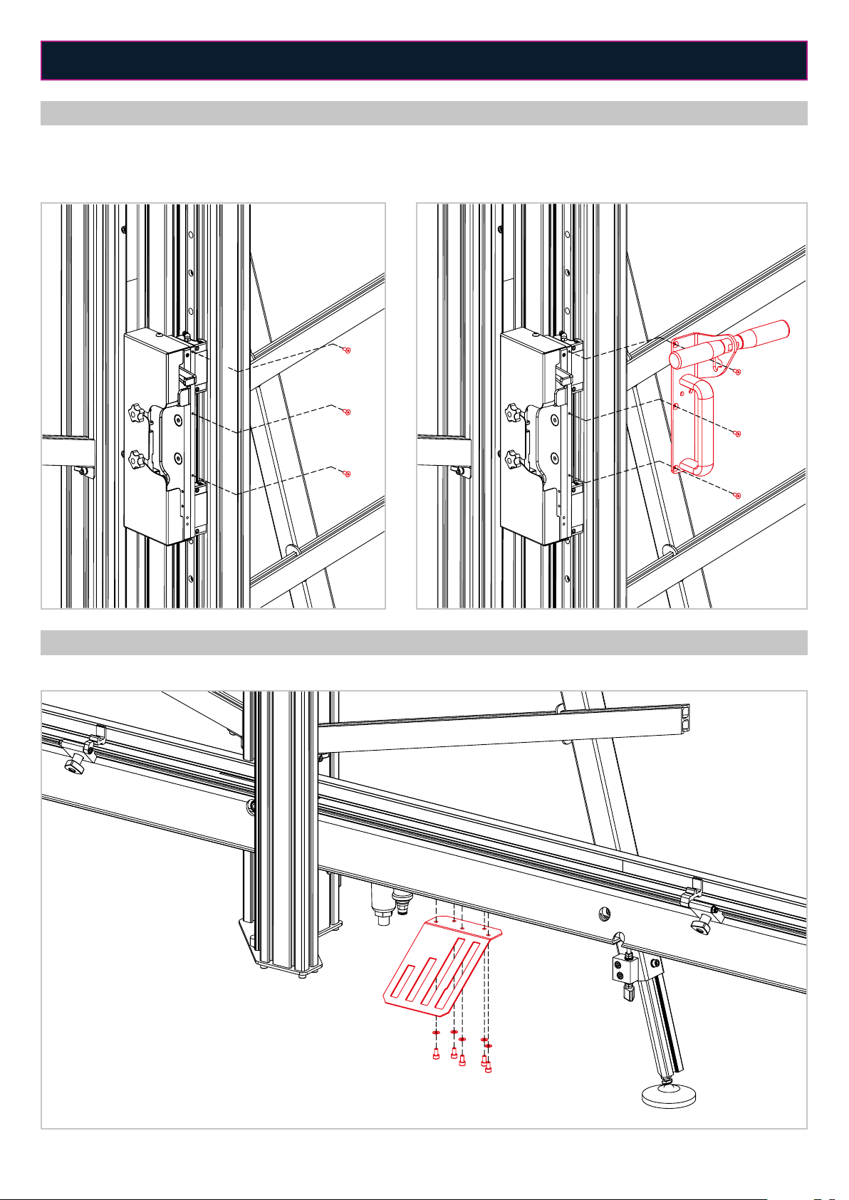
STAGE 8
Note: Stage valid only for the UpperCut Manual. For UpperCut Auto follows in Stage 9.
1. Remove the three screws from the cutting head holder (A).
2. Lay the double handle system group as shown in the figure and fix it using the three screws removed previously (B).
STAGE 9
1. Fit the cutting head support at the bottom of the horizontal support group and fix it using the five screws removed at the stage 4.
AB

14
ASSEMBLY INSTRUCTIONS
STAGE 10
1. Once all the parts have been assembled, screw the UpperCut to the wall or to the free standing accessory using the bracket shown in the figure (A).
A
A

15
6. Screw the UpperCut to the upper support of the free standing using
the two Allen screws supplied.
7. Screw the aluminum plate supplied to the free standing and the
bottom part of the UpperCut to increase the stability.
1. General view of the UpperCut Free Stan-
ding.
2. Slide the two nuts of the upper support
into the slots of the main body.
3. Tight the two screws once the upper
support is located as shown in the general
view.
4. Join the bottom support with the main
body by sliding the nuts of the brackets
into the slots of the profile.
5. Tight the screws once the bottom
support is located as shown in the general
view.
ACCESSORIES ASSEMBLY INSTRUCTIONS
FREE STANDING
Steps to follow in order to install the free standing for the UpperCut cutter: The free standing accessory is made up of three dierent parts: the
main body, the upper support and the bottom support. Before mounting the machine on the free standing the three parts need to be connected.

16
ACCESSORIES ASSEMBLY INSTRUCTIONS
ARM EXTENSION
Steps to follow in order to install the arm extension for the UpperCut cutter:
1. The same arm extension can be installed either on the right or on
the left side, depending on the position of the foot and the lateral
bracket.
2. Once the position has been defined, fit the screw into the appro-
priate hole and slide the nut into the slot of the foot. Tighten the
screw.
3. If it is required, change the position of the lateral bracket.
4. Fit the rib of the lateral bracket to the horizontal support profile.
5. Level the base of the arm extension with the horizontal support
profile and tighten all the horizontal and vertical screws to fix it.
6. There is the possibility to install an arm extension on each side of the UpperCut vertical cutter.

17
1. For UpperCut Manual:Assemble the
laser bracket to the cutting head support
using the M4x20 Allen screws supplied.
1. For UpperCut Auto:Assemble the laser
bracket to the cutting head support using
the M4x20 Allen screws supplied. Add the
aluminum spacer supplied between the
bracket and the support.
2. Screw the arm of the laser to the pre-
vious bracket using the M4x16 Allen screw
supplied.
3. Remove the protective cover by loose-
ning the three screws that hold it and the
two handles.
4. Fix the batteries holder to the cutting
head support using the two M4x6 Round
head screw supplied
5. Put the cover back and insert the laser
to its support. Fix it with the M4x16 Allen
screw.
How to adjust the laser?
1. Place the cutting head at the top of the machine and in a position where it does not actually cut the material but only marks it. Simply release
the cutting head backwards a little as explained in figure D on page 23.
2. Place a Foambard sheet and move the cutting head downwards to mark it.
3. Without removing the material, release the cutting head completely backwards and return it to the upper position.
4. Once this is done, match the laser to the mark on the material to adjust it.
ACCESSORIES ASSEMBLY INSTRUCTIONS
LASER
Steps to follow to install the laser accessory to the cutting head support:

18
SQUARING PROCESS
In order to get a correct cut, the UpperCut needs to be squared properly. Follow the next steps if the UpperCut is not squared, using a full sheet of
foam board 100 x 150 cm.
Step 1. Checking for squareness:
1. Place the semi-rigids cutting head to the cutting head holder.
2. Put the board on the right side of the machine vertically.
3. Set the right measuring stop at 90 cm.
4. Place the board to the measuring stop and hold it using the pneumatic clamp.
5. Cut the material.
6. Turn over the sheet of material like a page in a book – keep the bottom side on the bottom.
7. Set the measuring stop at 2 cm less than the initial cutting size (88 cm) and make a second cut.
8. Remove the sheet, measure the top edge and the bottom edge.
• If the machine is square, the two measurements should measure the same.
• If the machine is not square, the top and bottom measurements will not be the same.
If the top edge is greater, then the steel cylinder from the adjusting screw system has to be raised (A). If the top edge is smaller, then the steel
cylinder has to be lowered (B).
Note: It is important to record your measurements as the error is equal to ½ the dierence of the measurements you recorded. For example, if the
dierence between the top and bottom measures 4 mm, the machine is out of square by 2 mm.
Step 2. Squaring the machine:
1. Keep measuring stop at the same size (88 cm).
2. Loosen the screws from the lateral brackets (1, 2) and the nut from the left column of the main assembly (3). Check that the nut from the right
column (4) is properly tight.
ADJUSTING THE UPPERCUT
A B
4
3
2
1

19
ADJUSTING THE UPPERCUT
SQUARING PROCESS
Step 3.
Place the board on the machine, touching the measuring stop:
• If the material was greater at the top:
- Lower the cutting head so that it is positioned 1 millimeter above the top edge.
- Adjust the horizontal support group by raising the steel cylinder (turn the adjustment screw clockwise, viewed from above (A)) until the material
has passed the edge of the blade by 2 mm (in this example).
•If the material was smaller at the top:
-Lower the cutting head so that it is positioned 1 cm down from the top edge. Make sure that the material is touching the edge of the blade.
-Adjust the horizontal support group by lowering the steel cylinder (turn the adjustment screw counter-clockwise, viewed from above (B)) until
the gap between the material and the blade reaches 2 mm (in this example).
4. To verify that the machine is aligned, move the measuring stop 2 cm less (in this case 86 cm) and repeat Step 1, starting at point 4.
5. Keep repeating the above procedure until the machine is aligned.
6. Tighten the screws (1, 2) and the nut (3).
A B
20
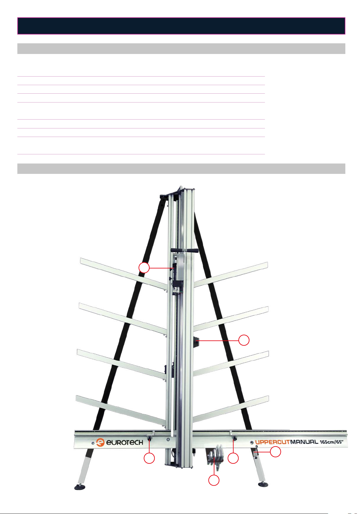
TECHNICAL DATA
CONTROL DEVICES UPPERCUT MANUAL
TECHNICAL CHARACTERISTICS UPPERCUT MANUAL
1. Cutting head system.
2. Pneumatic clamp switch.
3. Left measurement stop.
4. Right measurement stop.
5. Adjusting screw system.
6. Cutting heads support.
1
2
3 4
5
6
UC-210
UpperCut Manual 210 cm
UC-250
UpperCut Manual 250 cm
Cutting head operation Manual Manual
Clam system operation Pneumatic Pneumatic
Cutting height 210 cm / 82" 250 cm / 98"
Dimensions A x B x C 268 x 210 x 56 cm
105 x 82 x 22“
310 x 210 x 56 cm
122 x 82 x 22“
Weight 84 Kg / 185 lb 102 kg / 224 lb
Packing dimensions 278 x 49 x 46 cm 331 x 49 x 46 cm
Packing weight 114 Kg
126 Kg (with free standing)
130 Kg
144 Kg (with free standing)
This manual suits for next models
4
Table of contents
Popular Cutter manuals by other brands


Makita
Makita 4112HS instruction manual

Makita
Makita DCE090 instruction manual

Hitachi
Hitachi CL 14DSL Handling instructions

Bosch
Bosch Rotocut operating instructions

Cricut Expression
Cricut Expression 24" Personal Electronic Cutter user manual

Krug & Priester
Krug & Priester IDEAL 4305 operating instructions