Eurotech Player VIP User manual
Player VIP
User’s Manual


Player VIP User’s Manual
110140-20001, preliminary Page i
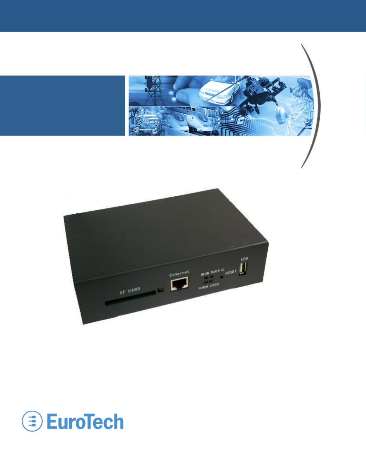
About the Cover Image
The cover image illustrates a Player VIP V2.0. A wireless version of the Player VIP that includes
an external antenna is available also. This manual is applicable to both products.
About this Manual
This manual describes how to use a Player VIP in your Video over IP application. It is intended
for system integrators and end-users.
Organization of this Manual
The manual organizes information in seven key sections:
Introduction Provides an overview of features and organization of the Player VIP.
Getting Started Describes the Player VIP development system.
Hardware Reference Defines location and function of connectors and indicators on the
Player VIP.
System Configuration Gives details on configuration of the Player VIP, as well as modes of
operation.
Troubleshooting Lists troubleshooting tips.
System Specifications Includes mechanical, environmental, and electrical specifications.
Revision History Identifies and explains product revisions.
To locate the information you need, try the following:
1. Browse the Table of Contents.
2. Follow cross-references between sections.
3. View and search this manual in PDF format.
Printing this Manual
This manual is designed for printing on both sides of an 8.5x11 inch paper sheet or two pages per
sheet but can be printed single-sided also.

Player VIP User’s Manual
Page ii 110140-20001, preliminary
Revision History
The following table summarizes the changes made between released revisions of the manual.
Revision
Description
By
1
Preliminary release
07/1
7
/08 ch
Errata, Addenda, and Further Information
Errata and addenda to this manual are posted on the Eurotech support forums along with the latest
release of the manual. Consult the support forums any time you need further information or feel
information in this manual is in error. You may access the forums from the Eurotech support site,
http://www.eurotech.com
In addition to manuals, the support forums include downloads, troubleshooting guides, operating
system updates, and answers to hundreds of questions about developing applications for Eurotech
products. You may also post questions you have about Eurotech products on the forums.
Copyright Notice
Copyright 2008 Applied Data Systems and Eurotech
Trademarks
This manual uses the following trademarks:
Windows and Internet Explorer are registered trademarks of Microsoft Corporation in the United
States and other countries.
CompactFlash is a trademark of the CompactFlash Association, http://www.compactflash.org/.
All other trademarks recognized.

Player VIP User’s Manual
110140-20001, preliminary Page iii
Table of Contents
About the Cover Image ................................................................................................................................... i
About this Manual........................................................................................................................................... i
Organization of this Manual ............................................................................................................................ i
Printing this Manual........................................................................................................................................ i
Revision History ............................................................................................................................................ ii
Errata, Addenda, and Further Information....................................................................................................... ii
Copyright Notice............................................................................................................................................ ii
Trademarks ................................................................................................................................................... ii
Table of Contents..........................................................................................................................................iii
1 Introduction ................................................................................................................................ 1
1.1 Overview ......................................................................................................................... 1
1.2 Features ........................................................................................................................... 1
1.2.1 Processor................................................................................................................ 1
1.2.2 Power Supply ......................................................................................................... 1
1.2.3 Memory.................................................................................................................. 1
1.2.4 Communications..................................................................................................... 1
1.2.5 Video ..................................................................................................................... 2
1.2.6 Audio..................................................................................................................... 2
1.2.7 User Interface......................................................................................................... 2
1.2.8 Mechanical............................................................................................................. 2
1.3 Block Diagram................................................................................................................. 2
2 Getting Started............................................................................................................................ 3
2.1 Development System........................................................................................................ 3
2.1.1 Components ........................................................................................................... 3
2.1.2 Connectivity........................................................................................................... 3
2.2 Optional Software ............................................................................................................ 4
3 Hardware Reference.................................................................................................................... 5
3.1 Connectors....................................................................................................................... 5
3.2 Indicators and Switches.................................................................................................... 6
4 System Configuration.................................................................................................................. 7
4.1 Web Server Access .......................................................................................................... 7
4.1.1 Crossover Cable Connection................................................................................... 7
4.1.2 Password-Protected Login ...................................................................................... 9

Player VIP User’s Manual
Page iv 110140-20001, preliminary
4.1.3 Account Management........................................................................................... 10
4.2 System Updates and Settings.......................................................................................... 11
4.2.1 Firmware Upgrades .............................................................................................. 11
4.2.2 Logo..................................................................................................................... 12
4.2.3 IP Address Display............................................................................................... 12
4.2.4 Factory Settings.................................................................................................... 12
4.3 Output Configuration ..................................................................................................... 13
4.3.1 Video ................................................................................................................... 13
4.3.2 Audio................................................................................................................... 14
4.4 Network Configuration................................................................................................... 15
4.4.1 Interface ............................................................................................................... 15
4.4.2 Settings ................................................................................................................ 15
4.4.3 Discovery Protocol Groups ................................................................................... 17
4.4.4 Multicast Configuration ........................................................................................ 18
4.5 Modes of Operation........................................................................................................ 20
4.5.1 Live Mode............................................................................................................ 20
4.5.2 Video On Demand (VOD) Mode .......................................................................... 23
4.5.3 Video Over Hard Drive (VOHD) Mode ................................................................ 25
5 Troubleshooting Guide.............................................................................................................. 27
6 System Specifications ............................................................................................................... 29
6.1 Mechanical Specifications.............................................................................................. 29
6.2 Environmental Specifications ......................................................................................... 29
6.3 Electrical Specifications ................................................................................................. 29
6.3.1 Power Specifications ............................................................................................ 29
6.3.2 Audio Specifications............................................................................................. 29
7 Product Revision History .......................................................................................................... 31
7.1 Hardware Revision......................................................................................................... 31
7.1.1 Identifying the Product ......................................................................................... 31
7.1.2 Revision History................................................................................................... 31
Revision V2.0
7.2 Firmware Revision......................................................................................................... 31
7.2.1 Identifying the Revision........................................................................................ 31
7.2.2 Revision History................................................................................................... 31
Version 2.0.0.1

110140-20001, preliminary Page 1
1 Introduction
1.1 Overview
The Player VIP is a MPEG-4/MPEG-2 decoder providing a flexible and cost-efficient
Video over IP (VIP) solution for distributed media systems. The Player VIP converts a digital
video stream to NTSC or PAL analog video and stereo audio outputs. The stream can originate
from a Streamer VIP video encoder, the VideoCenter software application, or local storage. The
Player VIP receives the video streams and displays the video locally.
The Player VIP supports three modes of operation: Live, Video On Demand (VOD), and
Video Over Hard Drive (VOHD). In Live mode, the Player VIP displays a stream from a
Streamer VIP, while the VideoCenter provides the stream in VOD mode. During VOHD mode,
the Player VIP plays back video files stored locally. An Internet browser configures the
Player VIP allowing easy customization to meet the needs of various media systems. The
Player VIP is ideal for entertainment, digital signage, and security applications.
This document applies to the latest revision of the Player VIP, as listed in the revision history
Section 7.
1.2 Features
1.2.1 Processor
•MIPS processor
•MPEG-4/MPEG-2 decoding engine
1.2.2 Power Supply
•12 V main power input
1.2.3 Memory
•32 MiB synchronous DRAM 1
•4 MiB Flash memory
•CompactFlash (CF), Type II
1.2.4 Communications
•10/100 Mbps Ethernet, RJ-45
•802.11g/b wireless (optional)
•USB 1.1 Host port
•EIA-232 Serial port
1MiB is the IEC abbreviation for mebibyte = 220 byte = 1 048 576 byte. The kibi and mebi
abbreviations are based on the 1998 IEC standard for binary multiples. For further reading, see
the US NIST web site, http://physics.nist.gov/cuu/Units/binary.html.
Player VIP User’s Manual
Page 2 110140-20001, preliminary
1.2.5 Video
•Video over IP input
•VGA, S-Video, and composite video outputs
•Video resolution up to NTSC (720 x 480) and PAL (720 x 576)
•Frame rate up to 30 fps for NTSC and 25 fps for PAL
•MPEG-4/MPEG-2 image decompression
•AVI, VOB, and MPG file formats
•Data rate up to 8 Mbps
1.2.6 Audio
•Stereo audio output
1.2.7 User Interface
•Configuration through Internet browser
•Static and dynamic IP assignment
•Password protection
1.2.8 Mechanical
•170 mm x 109 mm x 48 m m dimensions
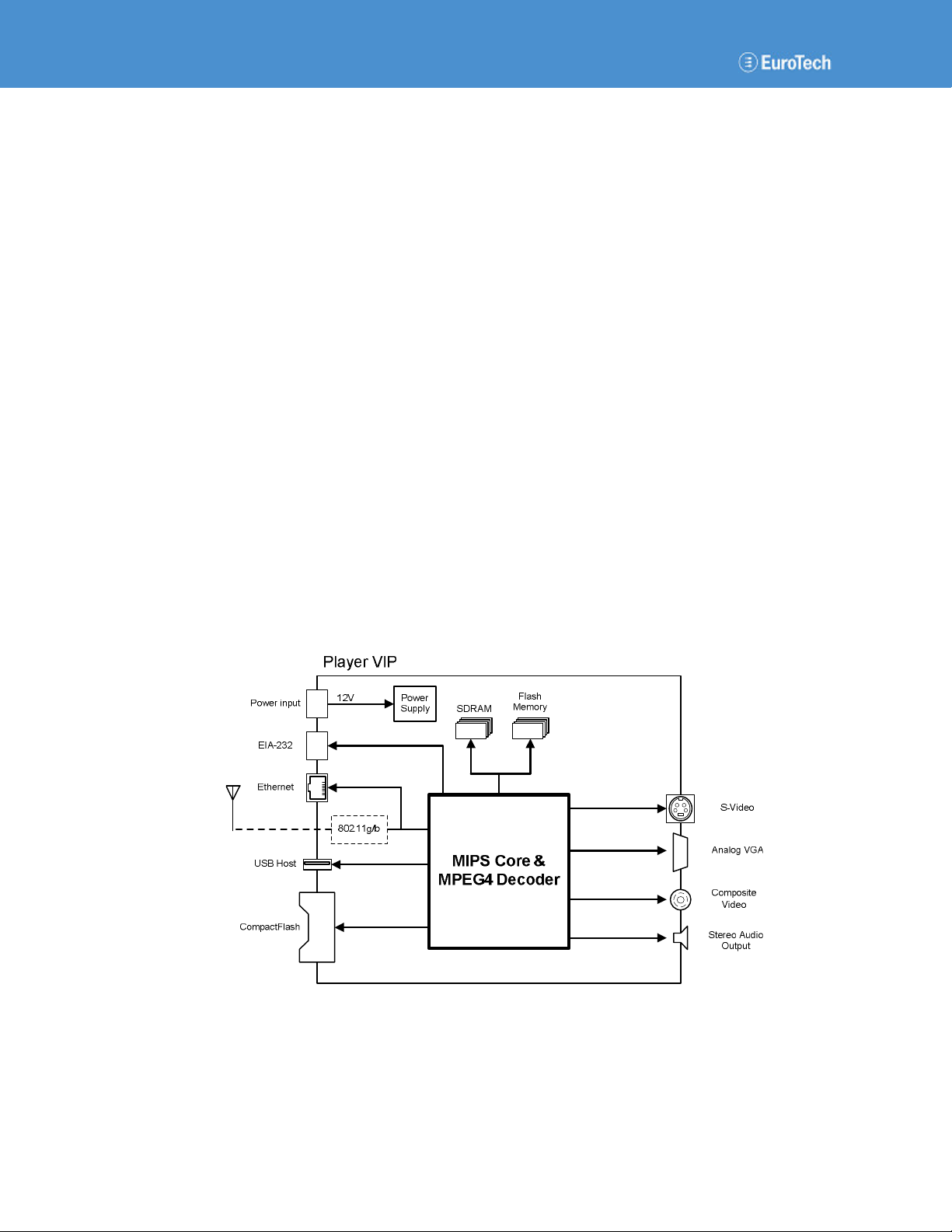
1.3 Block Diagram
The following diagram illustrates the hardware architecture of the Player VIP. Arrows indicate
direction of control and not necessarily signal flow.

110140-20001, preliminary Page 3
2 Getting Started
This section provides information on the initial use of the Player VIP development system.
2.1 Development System
The design of the Player VIP development system gets your video over IP system up and running
quickly. The default settings display video from a CF card to your VGA monitor with no
additional configuration required.
2.1.1 Components
The Player VIP development system consists of the following components:
•Player VIP
•CF card
•12 VDC power adapter
•Ethernet crossover cable
•VGA cable
•S-video cable
•User's Guide
•VideoCenter application (optional)
Please make sure you have received all the components before you begin your installation.
2.1.2 Connectivity
Connect the Player VIP Development System
To use the Player VIP, complete the following steps:
1. Connect the VGA video output to your monitor.
2. Insert the CF card.
3. Connect the power input to the 12 VDC adaptor.
Upon boot, the power LED located on the front panel lights indicating power to the system. A
boot screen appears followed by the IP address and subnet mask for approximately 20 seconds.

Player VIP User’s Manual
Page 4 110140-20001, preliminary
The following are the default settings for the Player VIP development system:
•IP Address 192.168.0.221
•Subnet Mask 255.255.255.0
After boot, video stored on the CF card plays continuously on the monitor.
2.2 Optional Software
VideoCenter is a Windows®-based application supporting the Player VIP decoder in VIP systems.
The application runs on a computer connected to the same network as Player VIP and allows you
to manage the media displayed by Player VIP.
Two service modes are supported simultaneously: VOD and VOHD. In VOD mode, VideoCenter
streams MEDIA files to the Player VIP. In VOHD mode, VideoCenter copies files to the
Player VIP local storage and sets the play schedule. VideoCenter supports a stand-alone
Player VIP or multiple units.
See the VideoCenter User’s Manual for a complete description of this application.
110140-20001, preliminary Page 5
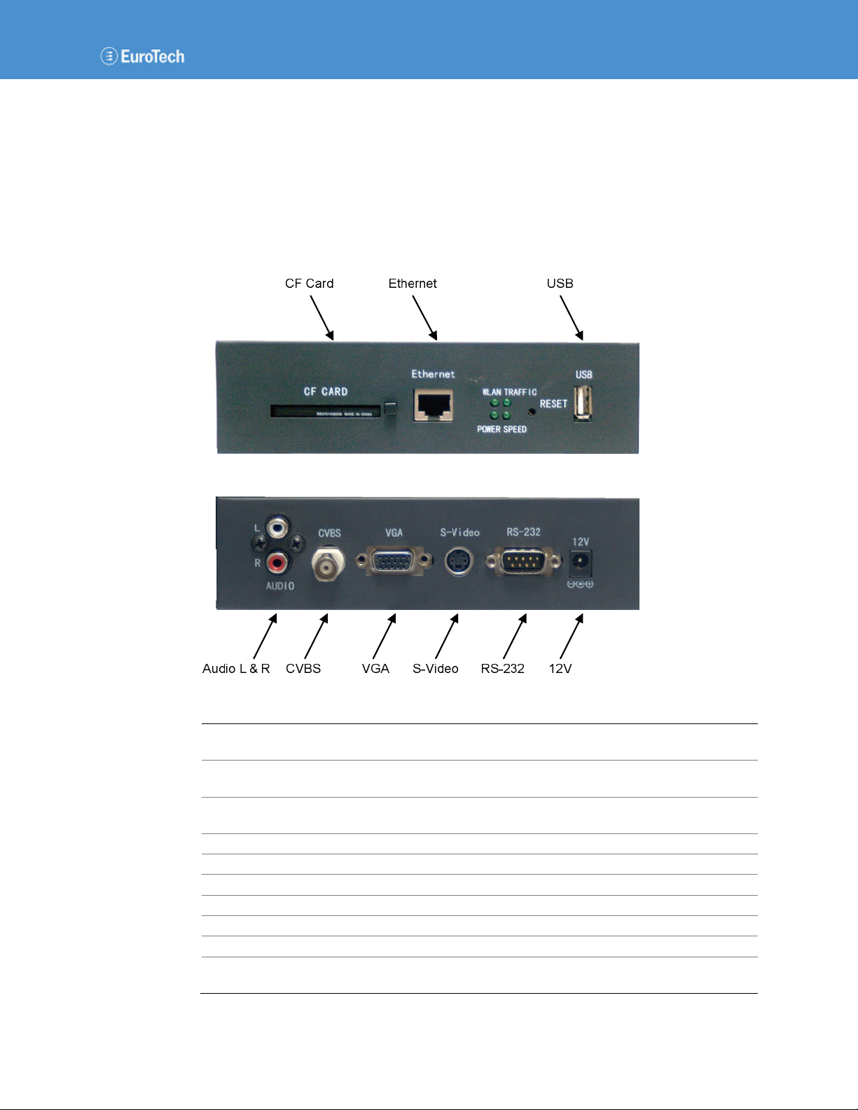
3 Hardware Reference
This section gives an overview of the hardware features of the Player VIP. The overview includes
location and function of connectors, indicators, and switches.
3.1 Connectors
The following diagram illustrates the location of connectors on the Player VIP, while the table
provides details about connector type and functionality.
Connector
Enclosure
Connector
Mating
Connector
Description
CF Card
CompactFlash
Type II socket
CompactFlash
Type II card
CompactFlash interface
Ethernet
RJ
-
45 jack
RJ
-
45 plug
10/100 Mbps
Ethernet network
USB
USB
Type A receptacle
USB
Type A plug
USB 1.1 Host port
Audio L & R
RCA jack
RCA plug
Audio output
CVBS
BNC socket
BNC plug
Compos
ite video output
VGA
DE
-
15 socket
DE
-
15 plug
VGA video output
S
-
Video
mini
-
DIN socket
4
-
pin
mini
-
DIN
plug
4
-
pin
Separate video output
RS
-
232
DB
-
9
socket
DB
-
9
plug
Serial interface
12
V
DC socket
2 mm
DC plug
2 mm
12
VDC power input
Wireless A
ntenna
(optional)
Wireless network adapter

Player VIP User’s Manual
Page 6 110140-20001, preliminary
3.2 Indicators and Switches
The Player VIP has four onboard light-emitting diodes (LEDs) indicating system operation, in
addition to a reset switch. The following diagram illustrates the location of the LEDs and reset
switch, while the table describes LED functionality.
LED
Description
WLAN
On indicates a wireless card is installed.
Traffic
Blinking indicates Ethernet activity.
Power
On indicates power to the Player
VIP.
Speed
On
indicates
the
network is operating at
100
Mbps
.
The reset switch is located on the front panel of the enclosure. Pressing this switch for more than
5 seconds restores the factory-default system settings. This system reset requires several seconds.

110140-20001, preliminary Page 7
4 System Configuration
The Player VIP provides a flexible solution for a variety of VIP applications. You can easily
configure the Player VIP to meet your existing media system structure. This section provides
details on this customization that include web server access, system updates and settings, output
configuration, network configuration, and modes of operation.
4.1 Web Server Access
A browser-based application configures the Player VIP. A computer connected to your network
and running a standard internet browser such as Internet Explorer® accesses the Player VIP web
server. The following sections explain the steps to access the web server of the Player VIP.
4.1.1 Crossover Cable Connection
To configure the Player VIP prior to installation in your network, connect the system directly to a
computer without a hub or switch. Use an Ethernet crossover cable between the Ethernet port of
the Player VIP and the computer. The computer’s network properties must be configured to
access the Player VIP.
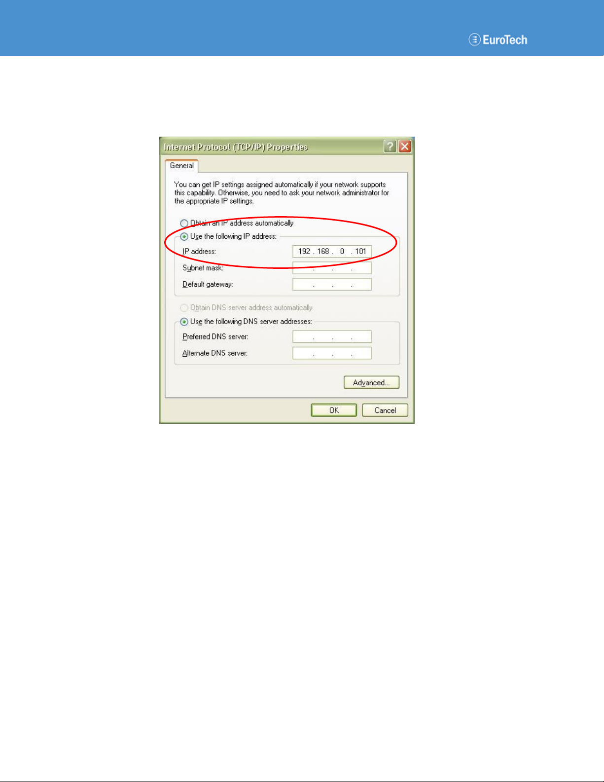
Configure Local Area Network (LAN) Properties
The following steps describe the settings for the Windows operating system:
1. Open the Network Connections window.
2. Click the right mouse button on Local Area Connection.
3. Open the Properties window.
4. In the General tab, select Internet Protocol (TCP/IP).
5. Click the Properties button as show in the following screen capture.
Player VIP User’s Manual
Page 8 110140-20001, preliminary
6. Select the Use the following IP address check box.
7. Type the IP address as shown in the following screen capture.
8. Click the OK button.
When finished configuring the Player VIP, restore your computer’s previous network settings.

System Configuration
110140-20001, preliminary Page 9
4.1.2 Password-Protected Login
Accessing the web server requires a password-protected account. The Player VIP is shipped with
a default administrative account. You can add or delete accounts as described in Section 4.1.3.
Log in to Web Server
To log in to the Player VIP web server, complete the following steps:
1. Start the web browser on your computer.
2. Type the Player VIP IP address in the browser URL.
The following URL is the default login:
•URL http://192.168.0.221
The following login window appears.
3. Type the account information for User name and Password.
The following is the default account information:
•User name admin
•Password admin
4. Click the OK button.
After login, the web server automatically displays the System page.
Player VIP User’s Manual
Page 10 110140-20001, preliminary
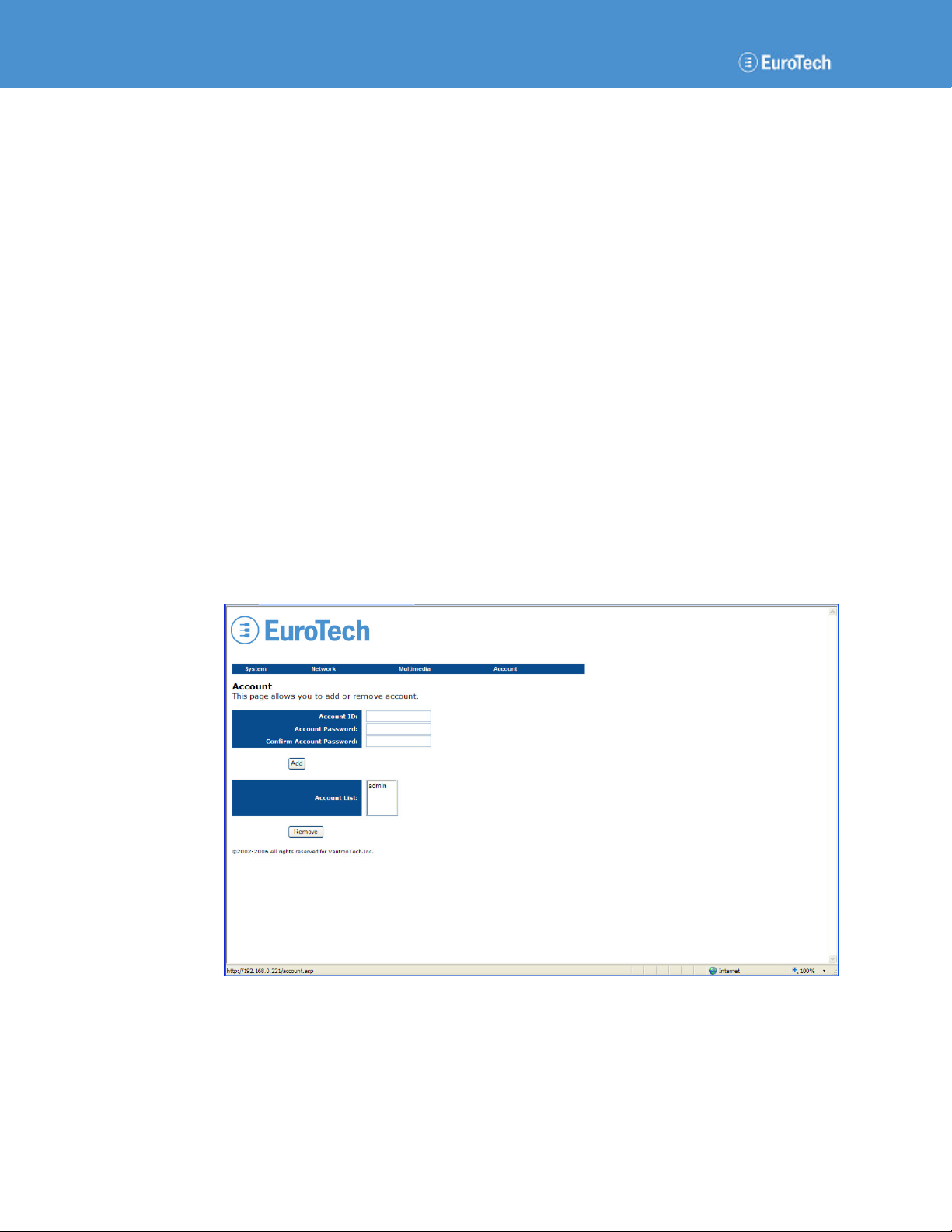
4.1.3 Account Management
In addition to the default administrative account, you can add up to 10 accounts and remove
accounts in the Account page.
Manage User Accounts
To add or delete an account, complete the following steps:
1. Navigate to the Account page.
2. To add an account, complete the following steps:
a. Type a new ID in the Account ID box.
b. Type a new password in the Account Password box.
c. Re-type the new password.
d. Click the Add button.
The new account is added, and the account ID is displayed in the Account List.
3. To delete an account, complete the following steps:
a. Select the unwanted account in the Account List box.
b. Click the Remove button.
The account is removed, and a new login window prompts you to log in again.
All accounts have the same system privileges. The following screen capture is the default
Account page.
System Configuration
110140-20001, preliminary Page 11
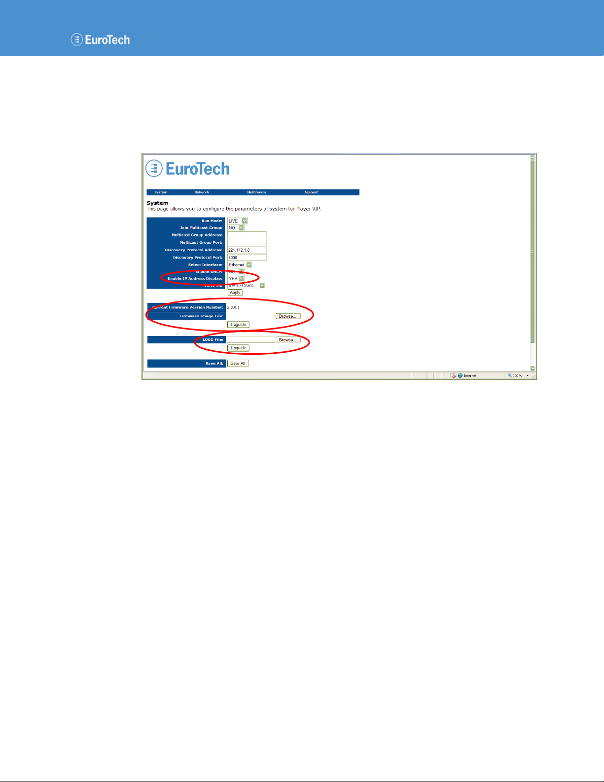
4.2 System Updates and Settings
The web server enables you to perform a variety of system upgrades and settings that include
upgrading the Player VIP firmware, changing the logo in the header of the pages, controlling the
IP address display at boot, and restoring the factory-default settings. The following screen capture
identifies these features.
4.2.1 Firmware Upgrades
You can upgrade the firmware using the web server. Notice that the System page contains the
current firmware version number.
Upgrade Firmware
To upgrade to a new version of firmware, complete the following steps:
1. Navigate to the System page.
2. Click the Browse… button on the right side of the Firmware Image File box.
You can browse your disk drive for the firmware file.
3. Select the firmware file, and then click Open.
The highlighted file appears in the Firmware Image File box.
4. Click the Upgrade button following the Firmware Image File box.
The Player VIP saves all settings and reboots to validate the change. Do not interrupt the
upgrade process or disrupt the power to the Player VIP until the upgrade is complete.
5. Close the web browser.
6. Log in to the web server again.
The new firmware version number appears in the Current Firmware Version Number field.

Player VIP User’s Manual
Page 12 110140-20001, preliminary
4.2.2 Logo
The Player VIP is shipped with a default logo in the header of each web page. You can change to
your company’s logo using the web server.
Change Logo
To change the logo, complete the following steps:
1. Navigate to the System page.
2. Click the Browse… button on the right side of the LOGO File box.
You can browse your disk drive for the logo file.
3. Select the logo file, and then click Open.
The highlighted file appears in the LOGO File box.
4. Click the Upgrade button following the LOGO File box.
5. Click the Save All button.
The Player VIP saves the new logo and reboots to validate the change.
6. Close the web browser.
7. Log in to the web server again.
The new logo appears in the header.
4.2.3 IP Address Display
With the default settings, the Player VIP IP address is displayed following the boot screen. You
can disable this display, and the IP address does not appear at boot.
Control IP Address Display
To control if the IP address displays at boot, complete the following steps:
1. Navigate to the System page.
2. From the Enable IP Address Display list, choose YES or NO.
3. Click the Apply button.
4. Click the Save All button.
The Player VIP saves the setting and reboots to validate the change.
4.2.4 Factory Settings
The Player VIP is shipped with factory-default settings as given in each section of this manual. In
addition to pressing the reset switch as described in Section 3.2, you can restore the factory-default
settings using the web server.
Restore Factory Settings
To restore the factory-default system settings, complete the following steps:
1. Navigate to the System page.
2. Click the Restore button.
The Player VIP restores all factory-default settings and reboots to validate the change.

System Configuration
110140-20001, preliminary Page 13
4.3 Output Configuration
This section details configuration of the video and audio outputs of the Player VIP.
4.3.1 Video
The Player VIP supports VGA, S-Video, and composite video outputs at resolutions up to
NTSC (720 x 480) and PAL (720 x 576). The VGA and S-Video outputs cannot be used
concurrently; therefore, you must select one or the other. The composite video output is available
independent of the video type selection.
Configure Video Output
To configure the Player VIP video output, complete the following steps:
1. Navigate to the Multimedia page.
2. From the Video Standard list, choose PAL, NTSC–3.58, or NTSC–4.43.
3. From the Video Type list, choose VGA or S-Video.
4. Type values into the Brightness, Contrast, Saturation, and Hue boxes. Valid values are 0-15.
The following screen capture contains the default values for the display:
•Video Standard NTSC-3.58
•Video Type VGA
•Brightness 6
•Contrast 6
•Saturation 0
•Hue 6
Player VIP User’s Manual
Page 14 110140-20001, preliminary
5. Click the Save button.
6. Navigate to the System page.
7. Click the Save All button.
The Player VIP saves all settings and reboots to validate the change.
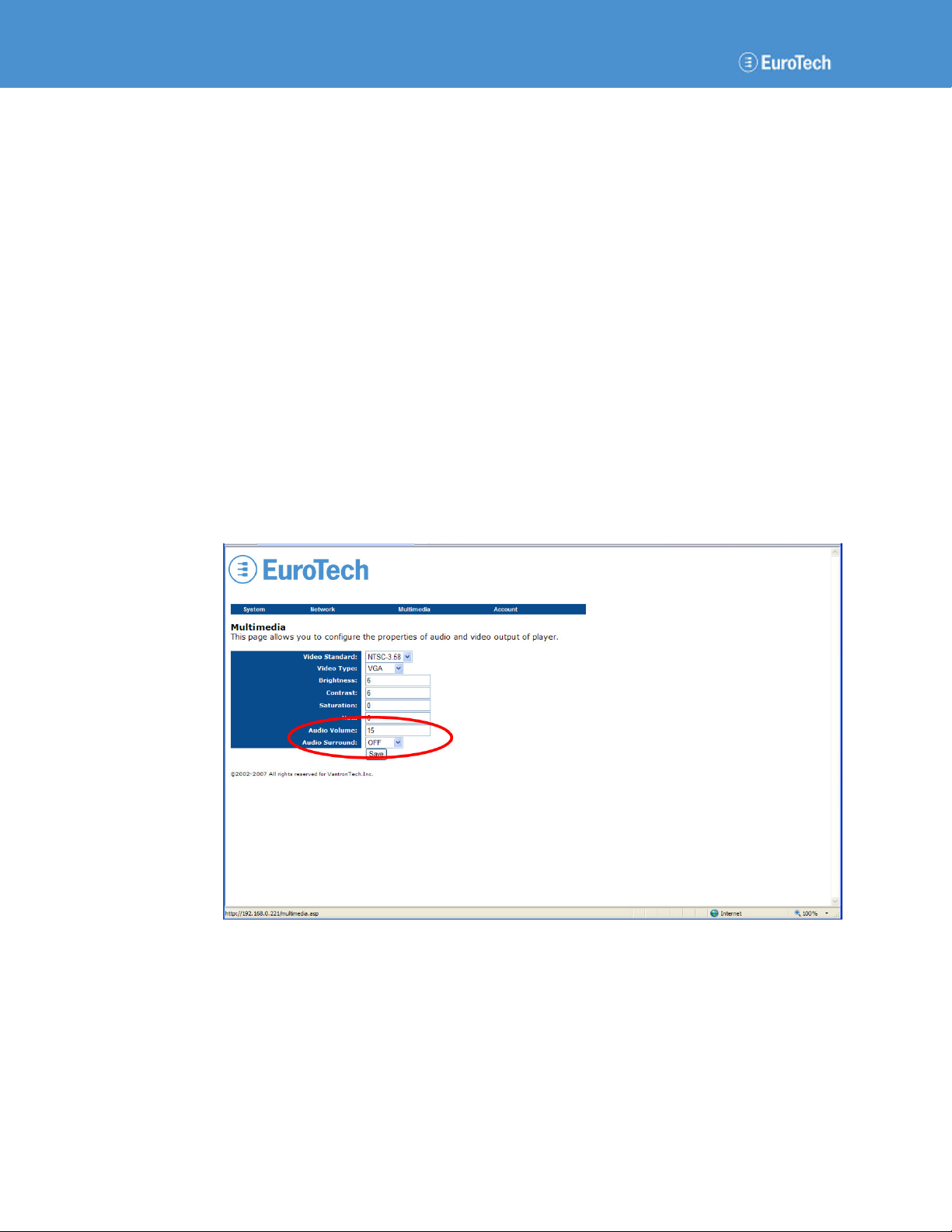
4.3.2 Audio
The Player VIP provides a direct stereo audio connection. No external amplifier is required. You
can adjust the audio volume and select surround options using the web server.
Configure Audio Output
To configure the Player VIP audio output, complete the following steps:
1. Navigate to the Multimedia page.
2. Type a value into the Audio Volume box. Valid values are 0-15.
3. From the Audio Surround list, choose OFF, Concert, Church, Passive, or Line.
The following screen capture contains the default values for the audio output:
•Audio Volume 15
•Audio Surround OFF
4. Click the Save button.
5. Navigate to the System page.
6. Click the Save All button.
The Player VIP saves all settings and reboots to validate the change.
Table of contents


