Eurotech An0066 User manual

Rev. 2.1
-
October 2010
-
ETH_An0066_USM21-2010-10
An0066
Adaptor Reference Guide

2 Introduction
An0066 Adaptor Reference Guide
Disclaimer
The information in this manual has been carefully checked and is believed to be accurate. Eurotech assumes no
responsibility for any infringements of patents or other rights of third parties, which may result from its use.
Eurotech assumes no responsibility for any inaccuracies that may be contained in this document. Eurotech makes no
commitment to update or keep current the information contained in this manual.
Eurotech reserves the right to make improvements to this document and/or product at any time and without notice.
Warranty
This product is supplied with a limited warranty. The product warranty covers failure of any Eurotech manufactured
product caused by manufacturing defects. Eurotech will make all reasonable effort to repair the product or replace it with
an equivalent alternative. Eurotech reserves the right to replace the returned product with an alternative variant or an
equivalent fit, form and functional product. Delivery charges will apply to all returned products.
Trademarks
All trademarks, both marked and not marked, appearing in this document are the property of their respective owners.
WEEE
The information below is issued in compliance with the regulations as set out in the 2002/96/CE directive, subsequently
superseded by 2003/108/CE. It refers electrical and electronic equipment and the waste management of such products.
When disposing of a device, including all of its components, subassemblies and materials that are an integral part of the
product, you should consider the WEEE directive.
This symbol has been attached to the equipment or, if this has not been possible, on the packaging,
instruction literature and/or the guarantee sheet. By using this symbol, it states that the device has been
marketed after August 13th 2005, and implies that you must separate all of its components when possible,
and dispose of them in accordance with local waste disposal legislations.
Because of the substances present in the equipment, improper use or disposal of the refuse can cause
damage to human health and to the environment.
With reference to WEEE, it is compulsory not dispose of the equipment with normal urban refuse,
arrangements should be instigated for separate collection and disposal.
Contact your local waste collection body for more detailed recycling information.
In case of illicit disposal, sanctions will be levied on transgressors.
RoHS
This device, including all it components, subassemblies and the consumable materials that are an integral part of the
product, has been manufactured in compliance with the European directive 2002/95/EC known as the RoHS directive
(Restrictions on the use of certain Hazardous Substances). This directive targets the reduction of certain hazardous
substances previously used in electrical and electronic equipment (EEE).
Related Documentation
For further information please refer to the appropriate User manual for the CPU or Peripheral that you are using the
adaptor with.
© 2010 Eurotech Spa
Eurotech S.p.A.
A member of the Eurotech Group
Via Fratelli Solari, 3/a
33020 - AMARO (UD)
ITALY

Introduction 3
An0066 Adaptor Reference Guide
Introduction
Manual Conventions
The following conventions are used throughout this manual.
The “Mode” of the register:
Symbol / Text
Definition
RW
Readable and Writable register
RO
Read only register
W
Meaning of the register when written
R
Meaning of the register when read
Hexadecimal numbering:
Hexadecimal numbers are indicated with an “h” suffix (for example: 11Ch)
Symbols and Text used in Pin-out tables:
Symbol / Text
Definition
◄
Input
►
Output
◄►
Bi-Directional
▬
Passive
Module
specific
Dependent on module installed
NC
Not Connected
Reserved
Use reserved to Eurotech, must remain unconnected
#
Active low signal
Warnings and Important Notices:
Within this manual you will find the following tables, please ensure that you read and understand these as
they are intended to highlight potential risks or precautions that should be taken.
Warnings:
Information to alert you to potential hazards:
Potential personal injury or damage to a system, device or program.
Information notes:
Indicates important features or instructions that should be observed

4 Introduction
An0066 Adaptor Reference Guide
Technical Assistance
If you have any technical questions or if you cannot isolate a problem with your device, please e-mail the
Eurotech Technical Support Team: email: techsupp@eurotech.it
RMA Requests
Before returning any Eurotech product, for any reason, you must e-mail the Eurotech Technical Support
Team on the above email address, giving the following information; you will then be sent an RMA number
(Returned Material Authorization) for the return of the material:
Model number (see Figure 1)
Serial number (see Figure 1)
Detailed fault description
Company Details
Contact details
Transportation
When transporting any module or system, for any reason, it should be packed using anti-static material and
placed in a sturdy box with enough packing material to adequately cushion it.
Warnings:
Any product returned to Eurotech that is damaged due to inappropriate packaging will
not be covered by the warranty!
Board labelling
On the external side of the ISA Bus connector, you will find several labels displaying the following:
•Batch Number
•Serial Number
•Model Number
•Hardware Revision
Note:
The actual location of these labels may vary depending on the product purchased.
For example: If no ISA bus is present, the PCI bus may be used instead.
However, the labelling formats will remain the same.
Figure 1. Board label locations
Serial Number
Model Number Hardware Revision
Batch Number

Table of Contents
Introduction...................................................................................................................................................... 3
Manual Conventions .......................................................................................................................................... 3
Technical Assistance ......................................................................................................................................... 4
RMA Requests................................................................................................................................................... 4
Transportation.................................................................................................................................................... 4
Board labelling ................................................................................................................................................... 4
Table of Contents ............................................................................................................................................ 5
Chapter 1 Adaptor kits ................................................................................................................................ 7
ACS-9094: RS485 CAN Interface Module......................................................................................................... 8
ACS-9094-00 ........................................................................................................................................................... 8
ACS-9094: Technical Details ................................................................................................................................... 9
ACS-9095: 10/100MB Ethernet Adaptor ......................................................................................................... 11
ACS-9095-05 ......................................................................................................................................................... 11
ACS-9095-07 ......................................................................................................................................................... 11
ACS-9095: Technical Details ................................................................................................................................. 12
ACS-9096: Gigabit Ethernet Adaptor .............................................................................................................. 15
ACS-9096-00 ......................................................................................................................................................... 15
ACS-9096: Technical Details ................................................................................................................................. 16
ACS-9092: USB Adaptor ................................................................................................................................. 18
ACS-9092-00 ......................................................................................................................................................... 18
ACS-9092-02 ......................................................................................................................................................... 18
ACS-9092: Technical Details ................................................................................................................................. 19
ACS-9093: Audio CODEC adaptor.................................................................................................................. 21
ACS-9093-00 ......................................................................................................................................................... 21
ACS-9093-01 ......................................................................................................................................................... 21
ACS-9093: Technical Details ................................................................................................................................. 22
ACS-9111: GPS Antenna kit ........................................................................................................................... 23
ACS-9111-00 ......................................................................................................................................................... 23
ACS-9111: Technical Details ................................................................................................................................. 24
Chapter 2 Cable Descriptions .................................................................................................................. 25
7000000033L: CAN Interconnection Cable ..................................................................................................... 26
7000000091L: CPU to Ethernet Adaptor......................................................................................................... 27
7000000155L: CPU to Gigabit Ethernet adaptor............................................................................................. 28
7000000160L: CPU to USB Adaptor ............................................................................................................... 29
7000000165L: CPU to AC97 CODEC Adaptor ............................................................................................... 30
7030000083L: CPU to Timers, Serial 3 & 4 and Ethernet Adaptor ................................................................. 31
7030000163L: CPU to Ethernet Adaptor......................................................................................................... 33
7030000240L: CPU to AC97 CODEC & USB Adaptors.................................................................................. 34
7030000245L: CPU to USB Adaptor ............................................................................................................... 35
7030000246L: CPU to 2x USB Adaptors ........................................................................................................ 36
7030000300L: AC97 CODEC Adaptor to 3x 2.5mm Jack sockets ................................................................. 37
7040000036L: Male MCX to Female SMA ...................................................................................................... 38
Chapter 3 Mechanical Parts...................................................................................................................... 39
1100000110L: 90-Degree mounting bracket ................................................................................................... 40
Chapter 4 Revision History....................................................................................................................... 41

(This page has been intentionally left blank)

Chapter 1 Adaptor kits


Adaptor kits 9
An0066 Adaptor Reference Guide
ACS-9094:
Technical Details
Connectors
Connector
Use
Type
Pins
Format
Pitch (mm)
J1
Module Interface
IDC
10
5x2
2.54
J2
Module I/O
DB9
9
DB9
--
J3
Power Supply
SIL
2
2x1
2.00
Jumpers
Jumper
Use
Options
Type
Default
JP1
Termination Resistor
Closed: 120 Ohm Inserted
Open: None
2 Pin
Open
JP2
Controller Selector
1-2: CAN Controller 1
2-3: CAN Controller 2
3 Pin
1-2
JP3
Controller Selector
1-2: CAN Controller 1
2-3: CAN Controller 2
3 Pin
1-2
JP4 Connect +12V from CPU Module to Pin 9 of
J2
Open: Not Connected
Closed: Connected
2 Pin Open
JP5
Connect Ground from CPU Module to the
CAN Ground
Open: Not Connected
Closed: Connected
2 Pin
Open

10 Adaptor kits
An0066 Adaptor Reference Guide
J1 Pinout
Pin
Signal
Pin
Signal
1
Ground
2
Vdd
3
Ground
4
CAN 1 Transmit
5
Ground
6
CAN 2 Transmit
7
Ground
8
CAN 1 Receive
9
+12 Volt
10
CAN 2 Receive
J2 Pinout
Pin #
Signal
1
Not Connected
2
CAN – Low
3
CAN – High
4
Not Connected
5
Not Connected
6
Ground
7
Ground
8
Not Connected
9
Ext Voltage
J3 Pinout
Pin #
Signal
1
Eternal Power
2
CAN Ground

Adaptor kits 11
An0066 Adaptor Reference Guide
ACS-9095:
10/100MB Ethernet Adaptor
ACS-9095-05
Eurotech
Part #
Qty.
CPU
Conn.
Type
Description
RoHS
Page
ACS-9095
1
ALL
Adaptor
10/100MB RJ45 Ethernet
12
1100000110L
2
ALL
Bracket
Mounting assembly
40
7000000091L
1
CPU-1213
J8
Cable
CPU to ACS-9095
27
7030000163L
1
CPU-1421
CPU-1452
CPU-1454
CPU-1462
CPU-1454
J12
J20
J20
J20
J20
Cable
CPU to ACS-9095
33
ACS-9095-07
Eurotech
Part #
Qty. CPU Conn. Type Description RoHS Page
ACS-9095
1
ALL
Adaptor
10/100Mb RJ45 Ethernet
12
1100000110L
2
ALL
Bracket
Mounting assembly
40
7030000083L
1
CPU-1421
J5
Cable
CPU to ACS-9095
31
12 Adaptor kits
An0066 Adaptor Reference Guide
ACS-9095:
Technical Details
Connectors
Connector
Use
Type
Pins
Format
Pitch (mm)
J1
CPU Interface
Minitek
10
5x2
2.54
J2
Female RJ45
RJ45
8
8x1
--
Jumpers
Jumper
Use
Options
Type
Pins
Default
JP1 ~ 3
Controller type
Open / Open / Open
Intel
Closed / Closed / Open
Realtek 8139D / 8139DL
Closed / Closed / Closed
Realtek 8019AS / 8139C
2.00mm
Jumpers
2
Closed / Closed / Closed
Realtek 8019AS / 8139C
1100000110L:
90-Degree mounting bracket

Adaptor kits 13
An0066 Adaptor Reference Guide
Default Jumper positions for JP1, JP2 and JP3
CPU Model Number
Connector
Ethernet Chipset
JP1
JP2
JP3
CPU-1213
J8
Realtek 8019AS
Closed
Closed
Closed
CPU-1421
J12
Realtek 8139C
Closed
Closed
Closed
CPU-1421
J5
Realtek 8139C
Closed
Closed
Closed
CPU-1452
J20
Intel 82562ET
Open
Open
Open
CPU-1454
J20
Intel 82562ET
Open
Open
Open
CPU-1462
J20
Intel 82562ET
Open
Open
Open
CPU-1454
J20
Intel 82562ET
Open
Open
Open
J1 Pinout
Pin
Signal
Pin
Signal
1
Vcc
2
Activity LED
3
+ Receive Data
4
- Receive Data
5
Link LED
6
Ground
7
Not Connected
8
Ground
9
+ Transmit Data
10
- Transmit Data
Notes:
Vcc on pin #1 is an output from the CPU module and should only be used LED anode supply.
The Value of Vcc on pin #1 can vary from 5V to 3.3V depending on the CPU module being used.
J2 Pinout
RJ45 Connector (Female)
Pin #
Signal
1
+ Transmit Data
2
- Transmit Data
3
+ Receive Data
4
Not Connected
5
Not Connected
6
- Receive Data
7
Not Connected
8
Not Connected

14 Adaptor kits
An0066 Adaptor Reference Guide
Schematics
Note on C1 and C3:
These capacitors are useful for EMI compliance.
Excessive capacitance can slow the 100 Mbps rise and fall times.
Unless there is some overshoot in the 100 Mbps mode, these caps are not necessary.

Adaptor kits 15
An0066 Adaptor Reference Guide
ACS-9096:
Gigabit Ethernet Adaptor
ACS-9096-00
Eurotech
Part #
Qty.
CPU
Conn.
Type
Description
RoHS
Page
ACS-9096
1
ALL
Adaptor
Gigabit Ethernet
16
1100000110L
2
ALL
Bracket
Mounting assembly
40
7000000155L
1
CPU-1454
J16
Cable
CPU to Gigabit Ethernet
28

16 Adaptor kits
An0066 Adaptor Reference Guide
ACS-9096: Technical Details
Connectors
Connector
Use
Type
Pins
Format
Pitch (mm)
J1
CPU Interface
Minitek
16
8x2
2.00
J2
RJ45 Connector
RJ45
8
RJ45
--
LED Activity Definitions
LED
Position
Colour
Use
Status
1
Right
Yellow / Green
Link
Off: Link 10
Green: Link 100
Yellow: Link 1000
2
Left
Green
Activity
On: Link Up
Blinking: Activity
J1 Pinout
Pin
Signal
Pin
Signal
1
MX-1
2
MX+1
3
MX-2
4
MX+2
5
MX-3
6
MX+3
7
MX-4
8
MX+4
9
Ground
10
Not Connected
11
Ground
12
Not Connected
13
Link LED 0
14
Activity LED1
15
Link 100 LED2
16
Link 1000 LED3
1100000110L:
90-Degree mounting bracket

Adaptor kits 17
An0066 Adaptor Reference Guide
J2 Pinout
Pin
Signal
1
+ Bidirectional Data A
2
- Bidirectional Data A
3
+ Bidirectional Data B
4
+ Bidirectional Data C
5
- Bidirectional Data C
6
- Bidirectional Data B
7
+ Bidirectional Data D
8
- Bidirectional Data D

18 Adaptor kits
An0066 Adaptor Reference Guide
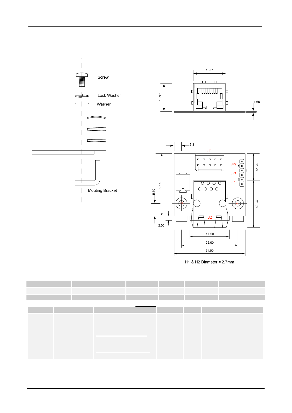
ACS-9092:
USB Adaptor
ACS-9092-00
Eurotech
Part #
Qty.
CPU
Conn.
Type
Description
RoHS
Page
ACS-9092
2
ALL
Adaptor
2-Port USB adaptor
19
1100000110L
4
ALL
Bracket
Mounting assembly
40
7030000240L
1
CPU-1452
CPU-1454
CPU-1462
CPU-1454
J14
J14
J14
J14
Cable
CPU Interface
34
7000000160L
1 CPU-1452
CPU-1454
CPU-1462
CPU-1464
J7
J7
J7
J7
Cable CPU Interface
29
ACS-9092-02
Eurotech
Part #
Qty. CPU Conn. Type Description RoHS Page
ACS-9092
2
ALL
Adaptor
2-Port USB adaptor
19
1100000110L
4
ALL
Bracket
Mounting assembly
40
7030000246L
1
CPU-1452
J16
Cable
CPU Interface
36

Adaptor kits 19
An0066 Adaptor Reference Guide
ACS-9092: Technical Details
Connectors
Connector
Use
Type
Pins
Format
Pitch (mm)
J1
CPU Interface
Male Minitek
8
4x2
2.00
J2
2x USB Ports
USB Type “A”
4
--
--
J3
Power Input
Male SIL
4
4x1
2.50
Jumpers
Jumper
Use
Qty Pins
Default
JP1
Connects VDD1# to VDD2#
2
Closed
1100000110L:
90-Degree mounting bracket

20 Adaptor kits
An0066 Adaptor Reference Guide
J1 Pinout
Pin
Use
Signal
Pin
Use
Signal
2
USB 1
Ground
1
USB 1
VDD1#
4
USB 1
- Data
3
USB 1
+ Data
6
USB 2
Ground
5
USB 2
VDD2#
8
USB 2
- Data
7
USB 2
+ Data
J2 Pinout
Female USB Socket
Port
USB Pin
PCB Pin
Use
Signal
Upper
1
1
USB 1
VDD
Upper
2
2
USB 1
- Data
Upper
3
3
USB 1
+ Data
Upper
4
4
USB 1
Ground
Lower
1
5
USB 2
VDD
Lower
2
6
USB 2
- Data
Lower
3
7
USB 2
+ Data
Lower
4
8
USB 2
Ground
Note: Port 1 is the Upper port and Port 2 is the Lower port
J3 Pinout
Pin
Use
Signal
1
External Power
VDD1#
2
External Power
Ground
3
External Power
Ground
4
Not Connected
Table of contents


