Stryker SYNK 4K Wireless System User manual

Transmitter:
Receiver:
0240031065
0240031075
SYNK® 4K Wireless System
DRAFT

DRAFT

Contents
Warnings and Cautions ........................................................................... 1
Warnings.....................................................................................................................1
Cautions......................................................................................................................2
Product Description ................................................................................ 4
Intended Use.............................................................................................................4
System Features....................................................................................... 6
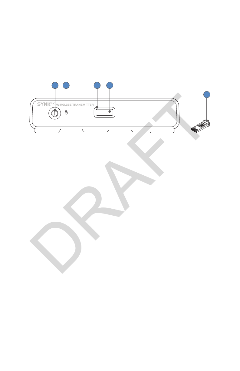
SYNK® 4K Wireless Transmitter Front Panel....................................................6
SYNK® 4K Wireless Transmitter Rear Panel......................................................7
SYNK® 4K Wireless Receiver Front Panel..........................................................8
SYNK® 4K Wireless Receiver Rear Panel............................................................9
Setup ......................................................................................................10
Device Compatibility........................................................................................... 10
Mounting the Receiver on a Display.............................................................. 11
Connecting Power from the AC Adapter ..................................................... 13
Connecting Power to the Receiver from a Display................................... 13
Setting up the SYNK®4K Wireless System .................................................... 13
Wireless Conguration.......................................................................... 16
Operation ...............................................................................................17
Pairing the Devices Using a Temporary Token (Blue) .............................. 17
Pairing the Devices Using a Permanent Token (Red)............................... 17
Removing a Permanent Link ............................................................................ 18
Troubleshooting ....................................................................................19
Cleaning .................................................................................................21
Cleaning and Disinfecting the Transmitter, Receiver, and Tokens ...... 21
Materials and Equipment .................................................................................. 22
Maintenance ..........................................................................................23
Inspecting the Transmitter and Receiver ..................................................... 23
Storage ..................................................................................................................... 23
Periodic Maintenance Schedule...................................................................... 23
Service Life.............................................................................................................. 23
Disposal.................................................................................................................... 24
Technical Specications........................................................................25
DRAFT

Electromagnetic Compatibility........................................................................ 28
Symbol Denitions................................................................................ 32
DRAFT

1
Warnings and Cautions
In this manual, the terms and denitions below apply.
• Warning: Possible injury to the patient or user.
• Caution: Possible damage to the equipment.
• Note: More information to clarify the instructions.
Warnings
To avoid potential serious injury to the user and the patient and/or damage to
this device, please note the following warnings.
1. Read this manual thoroughly and know its contents prior to using the
device.
2. Federal law (United States of America) restricts this device to sale by, or
on the order of, a physician.
3. This system is not suitable for use in the presence of ammable
anesthetic gases.
4. This equipment complies with FCC radiation exposure limits set forth for
an uncontrolled environment. This equipment should be installed and
operated with minimum distance 20 cm (7.9 inches) between the radiator
and your body.
5. Install this system in an operating room that complies with all applicable
IEC, CEC, and NEC requirements for safety of electrical devices. Any
installation or connection with other devices shall be evaluated for
electrical safety according to the IEC 60601-1.
6. This product is non-sterile and therefore should not be placed in the
sterile eld.
7. Although the device was fully tested at the factory before shipment,
the user should always test it for proper function prior to a surgical
procedure.
8. To achieve grounding reliability, connect the product to an AC adapter
that is connected to a hospital-grade power cord, and ensure the power
cord is plugged into a grounded power outlet. Do not use extension
power cords.
9. To avoid risk of electric shock, use only the hospital-grade power cord
furnished with the receiver and/or transmitter. Disconnect the receiver
and/or transmitter from the power supply to make connections or to
inspect the equipment.
10. Use Stryker HDMI cable only provided with the product. Use of third-
party HDMI cables with the camera console is not recommended due
DRAFT

2
to potential problems with secure connections or electromagnetic
compatibility. Use the provided HDMI high speed cable (or other Stryker-
approved HDMI cable) with the SYNK® 4K Wireless System.
11. Only connect items that have been specied as part of the SYNK® 4K
Wireless System or that have been specied as being compatible with the
system.
12. To avoid the risk of electric shock, this equipment must only be
connected to a supply mains with protective earth.
13. Do not place any heavy object on the power cord. Damage to the power
cord can cause re or electric shock.
14. Do not put any liquid or solid object into the device. If this occurs, unplug
the device and have it checked by qualied personnel before operating it
any further.
15. Use appropriate caution to prevent contact with uids if the receiver or
transmitter is being used with a power supply in patient environments.
16. To avoid electric shock, do not open the receiver or transmitter housings.
17. Do not modify this equipment without authorization of the manufacturer.
18. Attempt no internal repairs or adjustments not specically detailed in this
operating manual. Refer any adjustments, modications, and/or repairs to
Stryker Endoscopy or its authorized representatives.
19. Do not touch the device and a patient simultaneously, as there is a risk of
electric shock.
20. Do not touch the patient with signal input or output connectors.
Equipment with SIP/SOP connectors should either comply with
IEC60601-1 harmonized national standard or the combination should be
evaluated for safety.
21. For optimal operation of the SYNK® 4K Wireless System, leave a
minimum of 1m (3.3 ft) between any part of the System and portable RF
communications equipment.
22. To prevent tampering, physically secure the device when not in use.
Cautions
To avoid potential damage to this device, please note the following cautions.
1. Carefully unpack the system and check if any damage occurred during
shipment. If damage is detected, refer to the warranty.
2. Do not install the devices near sunlight, excessive dust, mechanical
vibration, or shock.
3. Keep the devices away from equipment that uses strong magnets (i.e.,
large loudspeakers).
DRAFT

3
4. To ensure electromagnetic compatibility, refer to the“Electromagnetic
Compatibility”section of this manual. The devices must be installed and
operated according to the EMC information provided in this manual.
5. Do not position the devices so that it is dicult to disconnect the power
cords from the supply mains.
6. Connect the devices to a hospital grade receptacle to achieve grounding
reliability.
7. To connect to an international power supply, use an attachment plug
appropriate for the power outlet.
8. Remove the power cord when transporting the devices.
9. Never operate the devices immediately after transportation from a cold
location to a warm location.
10. Power o the devices when they are not in use.
11. Unplug the receiver and transmitter if they are not to be used for an
extended period of time.
12. Pay close attention to the care and cleaning instructions in this manual. A
deviation may cause damage.
13. Changes or modications not expressly approved by the party
responsible for compliance could void the user’s authority to operate the
devices.
Note: This device complies with part 15 of the FCC Rules. Operation is subject
to the following two conditions: (1) This device may not cause harmful
interference, and (2) this device must accept any interference received,
including interference that may cause undesired operation.
The user is encouraged to try to correct the interference by one or more of the
following measures:
• Reorient or relocate the receiving unit.
• Increase the separation distance between the units.
• Connect the unit to an outlet on a circuit dierent from that to which
the other unit(s) are connected.
• Consult the manufacturer or eld service technician for help.
The warranty is void if any of these warnings or cautions are disregarded.
These products contain electrical waste or electronic equipment. They must
not be disposed of as unsorted municipal waste and must be collected
separately.
DRAFT

4
Product Description
The SYNK® 4K Wireless System wirelessly transfers video data from a
transmitter to up to two linked receivers. The transmitter provides an HDMI
input that supports 1080p and 4K video formats, and the receiver provides an
HDMI output supporting the same formats. Once the devices are linked, the
transmitter wirelessly transfers high-denition video to the receiver for output
on a secondary display.
At least one transmitter, one receiver, and a pairing token are required for full
functionality of the system. A link between the transmitter and the receiver(s)
is established by manually inserting a token in the transmitter and then in
the receiver(s). Encrypted network data is written onto the token from the
transmitter, and the data is decrypted in the receiver to establish a private
and secure connection. A token is a small memory device that is programmed
with frequencies allowed to establish a link.
The receiver can optionally be mounted to the back of the 32” 4K Surgical
Display (0240031050), and it comes with the necessary mounting hardware.
A dedicated power supply is included with the transmitter and the receiver
to provide power. Alternatively, a Y-cable is provided with the receiver so it
can share the 32”4K Surgical Display’s power supply (use when the receiver is
mounted to the back of that display).
The system transfers video data without controlling or altering the functions
or parameters of any connected devices.
Intended Use
The SYNK® 4K Wireless System is intended for wireless transmission of high
denition video data to secondary displays in a professional healthcare
setting. The system is a non-sterile reusable device not intended for use in the
sterile eld.
Contraindications
There are no contraindications for these devices.
DRAFT

5
SYNK® 4K Wireless Transmitter
Package Contents
• (1) SYNK® 4K Wireless Transmitter (0240031065)
• (1) Hospital-grade power cord (0105033001)
• (1) HDMI high speed cable, 2M (P39077)
• (2) Remote cables (0105206758)
• (1) Power supply (P27315)
• (2) Temporary tokens (blue) (0105208884)
SYNK® 4K Wireless Receiver
Package Contents
• (1) Receiver (0240031075)
• (1) Hospital-grade power cord (0105033001)
• (1) Power supply (P27315)
• (2) Shoulder bolts (P44094)
• (1) Y cable (P43614)
• (1) HDMI high speed cable, 2M (P39077)
DRAFT

6
System Features
This section outlines the features of the SYNK® 4K Wireless Transmitter and
Receiver.
SYNK® 4K Wireless Transmitter Front Panel
124
5
3
1. Power switch
(hard)
Powers transmitter ON and OFF.
2. Power Indicator Steady Green - Power is ON
3. Token Status
Indicator
Blinking White - Waiting for normal token
Green - Ready for pairing or Wireless link is
established
Amber - Warning, see Troubleshooting
Red - Error, contact service representative
4. Token Slot Token insertion site used to establish a wireless
connection
5. Token Initializes a wireless connection after insertion into
the transmitter and receiver
Note: The transmitter emits a pairing sound when a wireless link is
established. The transmitter emits a link drop sound when one or both
receiver links have been dropped.
DRAFT

7
SYNK® 4K Wireless Transmitter Rear Panel
123567
4
1. HUB Port Maintenance port (Stryker use only)
2. Remote 1 Connects to video source remote output 1
3. Remote 2 Connects to video source remote output 2
4. Micro USB Port Maintenance port (Stryker use only)
5. HDMI Out Connects to a primary display
6. HDMI In Connects to a digital input source
7. AC Power Inlet Connects to AC power adapter
DRAFT

8
SYNK® 4K Wireless Receiver Front Panel
124
5
3
1. Power switch
(hard)
Powers receiver ON and OFF
2. Power Indicator Steady Green - Power is ON
3. Token Status
Indicator
Blinking White - Waiting for normal token
Blinking Green - Attempting to pair
Green - Wireless link is established
Amber - Warning, see Troubleshooting
Red - Error, contact service representative
4. Token Slot Token insertion site used to establish a wireless
connection
5. Token Initializes a wireless connection after insertion into
the transmitter and receiver
DRAFT

9
SYNK® 4K Wireless Receiver Rear Panel
123456
1. HUB Port Maintenance port (Stryker use only)
2. Remote 1 Connects to Connected OR Hub Remote 1
3. Remote 2 Connects to Connected OR Hub Remote 2
4. Micro USB Port Maintenance port (Stryker use only)
5. HDMI Out Connects to a primary display.
6. AC Power Inlet Connects to AC power adapter
DRAFT

10
Setup
• When the SYNK® 4K Wireless System is interconnected with
other electrical devices, leakage currents may be additive,
resulting in electromagnetic emissions that can interfere
with the normal function of electronic medical equipment.
To properly control electromagnetic emissions and avoid
potential harm to the patient or user, ensure all electrical
devices are installed and interconnected according to the
requirements of IEC 60601-1.
• RF and other mobile communications equipment may
aect the normal function of the SYNK® 4K Wireless System.
When placing the SYNK® 4K Wireless System, follow the
instructions located in the “Electromagnetic Compatibility”
section of this manual.
Device Compatibility
For optimal use, the SYNK® 4K Wireless System is designed to work with
the 1688 Camera Control Unit (1688010000), the Connected OR Hub
(0240200100) with software version 1.2.3 or higher, and the 32”4K Surgical
Display (0240031050). All features and instructions described in this user
manual apply to this system unless otherwise noted.
The following table lists alternate video sources that are compatible with
the SYNK® 4K Wireless System. Please contact a Stryker representative for
assistance.
Alternate Video Sources
1588010000 1588 AIM Camera Control Unit (CCU)
• Connect to the system using an HDMI to DVI Cable
(P32235)
0240099250 S-Video/Composite to HDMI Converter
0240099255 VGA/RGB to HDMI Converter
0240099260 3G-SDI to HDMI Converter
0240099265 DVI to HDMI Converter
DRAFT

11
Mounting the Receiver on a Display
The receiver can be mounted on the back of a 32” 4K Surgical Display
(0240031050), on a roll stand or cart.
Power o and unplug the receiver and display from the
electrical outlets before mounting.
1. Insert the provided shoulder bolts into the back of the display.
2. Ensure the shoulder bolts are secured before proceeding.
3. Align the key holes on the bottom of the receiver with the shoulder bolts
DRAFT

12
on the display.
4. Push the receiver forward, then rotate it clockwise until you feel it lock
rmly into place.
DRAFT

13
Connecting Power from the AC Adapter
The transmitter must be powered by the AC adapter provided in its
packaging. The receiver may be powered by the AC adapter provided in its
packaging or by using the provided Y-cable to draw power from the 32” 4K
surgical display. To power the receiver from the display, see the next section.
Follow these instructions to connect power to the transmitter and receiver
from the AC power adapter.
1. Using the provided power cord, connect the AC power adapter to a
hospital-grade outlet.
2. Insert the AC power adapter’s outlet plug into the transmitter’s or
receiver’s AC power inlet.
Connecting Power to the Receiver from a Display
Follow these instructions to connect power to a receiver that is mounted on
the back of a 32” 4K Surgical Display.
Periodically check the display’s power supply for usability.
Replace the power supply if needed.
1. Disconnect the display’s power supply from the 24 V input on the display.
2. Using the provided Y cable, connect the display’s power supply to the 24
V input on the display.
3. Insert the Y cable outlet plug into the receiver’s AC power inlet.
Setting up the SYNK®4K Wireless System
The SYNK®4K Wireless System can be set up in a number of dierent ways,
depending upon which video sources and other visualization equipment are
available. This section describes two generic congurations.
Note: When the Connected OR Hub and two camera control units are used,
you can switch between Channels 1 and 2. Review the Connected OR Hub
Instructions for Use (P35947) for more information.
Please contact a Stryker representative for assistance.
Before connecting any device to the SYNK®4K Wireless System,
all devices must be installed according to their respective
instructions, and the combination of devices must meet the
electrical safety requirements of IEC 60601-1.
DRAFT

14
Generic Video Source Direct to Display
Refer to the following instructions and wiring diagram for a typical wireless
conguration.
Display
Video
Source Transmitter Receiver
Display
HDMI HDMI
HDMI
1. Using the provided HDMI cable, connect the HDMI OUT on the video
source to the HDMI IN on the transmitter.
• The HDMI OUT on the transmitter can be connected to the HDMI IN on
a secondary display.
2. Using the provided HDMI cable, connect the HDMI OUT on the receiver to
the HDMI IN on the primary display.
3. (Optional) Repeat Step 2 for a second receiver.
4. Link the receiver to the transmitter with the token. (If using a temporary
token, linking is required each time the receiver or transmitter is powered
on.)
5. (Optional) Link a second receiver directly after linking the rst receiver. Do
not reconnect the token to the transmitter.
DRAFT

15
Generic Remote Port Routing
Refer to the following instructions and wiring diagram for a wireless
conguration where the camera control unit is located separately from the
Connected OR Hub.
Note: Obtain a second set of remote cables from another Stryker visualization
system before proceeding.
Camera
Control
Unit
Transmitter Receiver
Connected OR
HUB
HDMI HDMI
HDMI
Remote Cables
Remote
Cables
Display
1. Using the provided HDMI cable, connect the HDMI OUT on the camera
control unit to the HDMI IN on the transmitter.
• The HDMI OUT on the transmitter can be connected to the HDMI IN on
a secondary display.
2. Using a provided remote cable, connect the Remote Out 1 on the camera
control unit to the Remote 1 on the transmitter.
3. Using a provided remote cable, connect the Remote Out 2 on the camera
control unit to the Remote 2 on the transmitter.
4. Using the provided HDMI cable, connect the HDMI OUT on the receiver to
the HDMI IN 1 (4K) on the Connected OR Hub.
5. Using a remote cable, connect the Remote 1 on the receiver to the
Remote 1 on the Connected OR Hub.
6. Using a remote cable, connect the Remote 2 on the receiver to the
Remote 2 on the Connected OR Hub.
7. Link the receiver to the transmitter with the token. (If using a temporary
token, linking is required each time the receiver or transmitter is powered
on.)
DRAFT

16
Wireless Conguration
The SYNK® 4K Wireless System uses a radio-frequency (RF) link to deliver
high-denition video signals in real time. Each system uses a portion of the RF
spectrum commonly referred to as a “channel” to broadcast its signal. The list
of allowed channels is regulated and varies by region.
The SYNK® 4K Wireless System uses 40 MHz channels in the 5.170-5.850 GHz
spectrum. The 5.170-5.850 GHz spectrum is also used by 802.11a/n/ac devices
as well as 5.8 GHz cordless phones. The System uses an automatic frequency
selection (AFS) mechanism in combination with a passive scanning capability
to maintain compatibility with these devices and identify unoccupied
channels for use.
Each linked SYNK® 4K Wireless System requires two 40 MHz channels to
properly operate. The System is designed to transmit video on a single 40
MHz channel and allocate an additional 40 MHz channel as a backup in case
of co-channel interference. Systems that are separated by a large distance
may use the same channel.
Note: The SYNK® 4K Wireless System uses a proprietary transmission method,
which cannot connect to or be accessed by 802.11 devices or 5.8 GHz cordless
phones.
In order to make sure that there are enough free channels for each SYNK® 4K
Wireless System, follow the steps outlined below:
1. Contact your IT administrator to determine if 802.11a or 802.11n WiFi is
in use at your facility. If so, note which channels are in use in or near each
SYNK® 4K Wireless System installation location.
2. Determine if any 5.8 GHz cordless phones are in use at your facility. If so,
note their locations.
3. For each SYNK® 4K Wireless System installation location, ensure that there
are two unused 40 MHz channels per SYNK® 4K Transmitter installed. If a
5.8 GHz cordless phone is used in the vicinity, assume that channels 149-
165 are occupied.
Contact your Stryker sales representative for more details.
DRAFT
This manual suits for next models
2
Table of contents
Other Stryker Receiver manuals
Popular Receiver manuals by other brands

Harman Kardon
Harman Kardon AVR 158 quick start guide

Horizon Hobby
Horizon Hobby Spektrum Smart SR6100AT instruction manual

Avantree
Avantree Clipper Pro user manual

Ferguson
Ferguson ARIVA Link 200 user manual

Extron electronics
Extron electronics MTP U R A Specification sheet

Marantz
Marantz SR4600 user guide