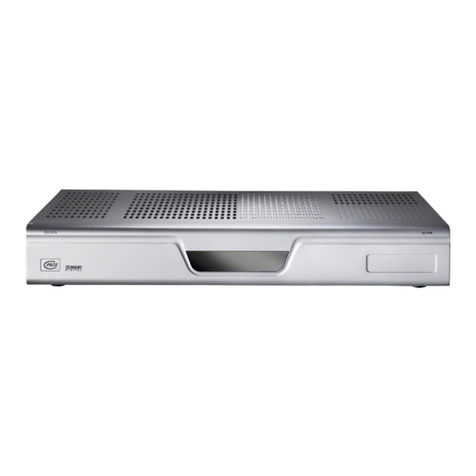
Eurotherm Chessell 4100G User manual

Artisan Technology Group is your source for quality
new and certied-used/pre-owned equipment
• FAST SHIPPING AND
DELIVERY
• TENS OF THOUSANDS OF
IN-STOCK ITEMS
• EQUIPMENT DEMOS
• HUNDREDS OF
MANUFACTURERS
SUPPORTED
• LEASING/MONTHLY
RENTALS
• ITAR CERTIFIED
SECURE ASSET SOLUTIONS
SERVICE CENTER REPAIRS
Experienced engineers and technicians on staff
at our full-service, in-house repair center
WE BUY USED EQUIPMENT
Sell your excess, underutilized, and idle used equipment
We also offer credit for buy-backs and trade-ins
www.artisantg.com/WeBuyEquipment
REMOTE INSPECTION
Remotely inspect equipment before purchasing with
our interactive website at www.instraview.com
LOOKING FOR MORE INFORMATION?
Visit us on the web at www.artisantg.com for more
information on price quotations, drivers, technical
specications, manuals, and documentation
Contact us: (888) 88-SOURCE | sales@artisantg.com | www.artisantg.com
SM
View
Instra

ε
Model 4100G
Video recorder
Technical manual
EUROTHERM
CHESSELL
4100G
Artisan Technology Group - Quality Instrumentation ... Guaranteed | (888) 88-SOURCE | www.artisantg.com

Artisan Technology Group - Quality Instrumentation ... Guaranteed | (888) 88-SOURCE | www.artisantg.com

100mm GRAPHICS RECORDER TECHNICAL MANUAL
HA249875
Issue 1 Jan 99 Section i
Page i - 1
100mm Graphics Recorder
Technical Manual
Overall List of Contents
Section Page
All rights are strictly reserved. No part of this document may be reproduced, stored in a retrieval
system or transmitted in any form, or by any means, without the prior, written, permission of the
copyright owner.
Eurotherm Recorders Ltd. reserves the right to alter the specification of its products from time to time
without prior notice. Although every effort has been made to ensure the accuracy of the information
contained herein, it is not warranted or represented by Eurotherm Recorders Ltd. to be a complete or
up-to-date description of the product.
© 1999 Eurotherm Recorders Ltd.
STATIC ELECTRICITY .................................................................. I - 4
TERMINOLOGY....................................................................I - 4
1 OVERVIEW
1.1 INTRODUCTION................................................................ 1 - 2
1.1.1 Manual layout.......................................................................1 - 2
1.2 TECHNICAL SPECIFICATION............................................... 1 - 2
1.2.1 Recorder ..............................................................................1 - 3
1.2.2 Input board...........................................................................1 - 4
1.2.3 Relay outputs ........................................................................1 - 5
1.2.4 Analogue outputs ..................................................................1 - 6
1.2.5 Event inputs ..........................................................................1 - 6
1.2.6 Serial communications ...........................................................1 - 6
1.2.7 Transmitter Power supply ........................................................1 - 6
1.3 THE RECORDER ................................................................. 1 - 7
1.3.1 General description ...............................................................1 - 7
ENCLOSURE ........................................................................1 - 7
DISPLAY ...............................................................................1 - 7
KEYBOARD FUNCTIONS ......................................................1 - 7
INPUTS ................................................................................1 - 7
OPTIONS.............................................................................1 - 8
1.3.2 Recorder functions .................................................................1 - 8
MEASUREMENT OF PROCESS VARIABLES ..............................1 - 8
JOBS ...................................................................................1 - 9
MESSAGE TYPES ..................................................................1 - 10
LOGS ..................................................................................1 - 10
ARCHIVE INTERVAL ....................................................1 - 10
ALARMS ..............................................................................1 - 10
INTERNAL EVENTS ...............................................................1 - 11
MATHS PACK .......................................................................1 - 11
FUNCTIONS ..............................................................1 - 11
TOTALISERS/COUNTERS/TIMERS (TCT) OPTION ....................1 - 12
TOTALISERS ...............................................................1 - 12
COUNTERS ...............................................................1 - 12
TIMERS ......................................................................1 - 12
OPERATOR ACCESS PERMISSION .........................................1 - 12
(Continued)
Artisan Technology Group - Quality Instrumentation ... Guaranteed | (888) 88-SOURCE | www.artisantg.com

100mm GRAPHICS RECORDER TECHNICAL MANUAL
HA249875
Issue 1 Jan 99
Section i
Page i - 2
LIST OF CONTENTS (Cont.)
Section Page
2 FAULT FINDING
2.1 FAULT FINDING GUIDE ...................................................... 2 - 3
2.1.1 Recorder completely inoperative..............................................2 - 3
2.1.2 Door resets continuously .........................................................2 - 4
2.1.3 Touch screen 'offset'...............................................................2 - 4
2.1.4 Screen saver not working .......................................................2 - 4
2.1.5 Measurements outside specified tolerance ................................2 - 4
2.1.6 Battery low/battery flat message .............................................2 - 4
2.1.7 Disk problems .......................................................................2 - 4
DISK LIFE ESTIMATES ............................................................2 - 4
ENVIRONMENT ...................................................................2 - 5
SYSTEM ERROR: DISK OVERDRIVE .........................................2 - 5
MULTIPLE FILES .....................................................................2 - 5
NO DISK ICON....................................................................2 - 5
VISIBLE DAMAGE TO THE DISK SURFACE...............................2 - 5
DOS-TYPE MESSAGES AT DISPLAY AND PRODUCT RESETS .....2 - 5
2.2 INPUT ADJUST................................................................... 2 - 6
2.2.1 Adjustment procedure ............................................................2 - 6
2.2.2 Default configuration..............................................................2 - 7
2.3 CALIBRATION.................................................................... 2 - 8
2.3.1 DC Inputs .............................................................................2 - 8
EQUIPMENT REQUIRED ........................................................2 - 8
CALIBRATION CHECK...........................................................2 - 8
2.3.2 Internal cold junction compensation (CJC) checking ...................2 - 9
2.3.3 Resistance inputs ...................................................................2 - 9
EQUIPMENT REQUIRED ........................................................2 - 9
CALIBRATION CHECK...........................................................2 - 9
2.4 RECORDER MESSAGES...................................................... 2 - 11
BAD REMOTE CJ TEMP .........................................................2 - 11
BAT BACK RAM CLEARED .....................................................2 - 11
BATTERY FAILURE..................................................................2 - 11
CLOCK FAILURE....................................................................2 - 11
CLR DISK OVERDRIVE ...........................................................2 - 11
DISK CORRUPT - PLEASE REPLACE .........................................2 - 11
DISK WORN - PLEASE REPLACE.............................................2 - 11
DV RUN TIME ERROR............................................................2 - 11
EEPROM DB DEFAULTED........................................................2 - 12
INPUT CHAN FAILURE...........................................................2 - 12
INVALID INDEX.....................................................................2 - 12
INVALID CONFIG .................................................................2 - 12
MODEM FAILURE..................................................................2 - 12
OUTPUT CH FAILURE ............................................................2 - 12
> RANGE ............................................................................2 - 12
< RANGE ............................................................................2 - 12
(Continued)
Artisan Technology Group - Quality Instrumentation ... Guaranteed | (888) 88-SOURCE | www.artisantg.com
Table of contents
