Eurotron MicroCal P200 Series User manual

ENGLISH
Eurotron Instruments S.p.A - Viale F.lli Casiraghi 409/413 – I 20099 Sesto S. Giovanni (MI) – Tel.: +39-022488201 – Fax: +39-022440286 – e-mail: info@eurotron.com
http://www.eurotron.com
M
Mi
ic
cr
ro
oC
Ca
al
l
P
P2
20
00
0
2 channels multifunction calibrators
Instruction Manual
MM850470 ed.1a

Instruction Manual MM850470 ed.1a
2
INTRODUCTORY NOTE
ATTENTION: THIS MANUAL MUST BE REFERRED TO INSTRUMENTS WITH SERIAL NUMBER 52506 AND FIRMWARE VERSION 4.000 ONWARDS.
This manual has been with all the information you need to install, operate and maintain the Pressure Calibrator MicroCal P200 and its
accessories.
Eurotron has used the best care and efforts in preparing this book and believes the information in this publication are accurate. The Eurotron
products are subjected to continuous improvement, in order to pursue the technological leadership; these improvements could require changes to
the information of this book.
Eurotron reserves the right to change such information without notice.
No part of this document may be stored in a retrieval system, or transmitted in any form, electronic or mechanical, without prior written permission
of Eurotron Instruments S.p.A.
MicroCal P200 Calibrator uses sophisticated analogic and digital technologies. Any maintenance operation must be carried out by qualified
personnel ONLY. Eurotron supplies instructions and operative procedures for any operation on the instrument. We recommend to contact our
technicians for any support requirements.
MicroCal P200 is fully tested in conformity with the directive n°89/336/CEE Electromagnetic Compatibility. Eurotron shall not be liable in any
event, technical and publishing error or omissions, for any incidental and consequential damages, in connection with, or arising out of the use of
this book.
All right reserved
Copyright © 2003 EUROTRON Instruments S.p.A.
Viale Fratelli Casiraghi 409/413
20099 Sesto San Giovanni (MI) – Italy
Tel.: +39-02 248820.1 – Fax: +39-02 2440286

Instruction Manual MM850470 ed.1a
3
CONTENTS
1GENERAL............................................4
1.1 Safety warning............................................5
1.2 Ordering code.............................................6
1.3 Accessories ................................................7
1.4 Pre-operational check.................................8
1.5 Technical specifications..............................9
2DESCRIPTION...................................11
2.1 Keyboard ..................................................12
2.2 Display......................................................13
2.3 Power supply ............................................14
2.4 Electrical connections...............................14
3GETTING STARTED..........................16
3.1 Unpacking.................................................16
3.2 Charging the battery .................................16
3.3 Power up...................................................16
3.4 Automatic channel protections..................16
3.5 Date and time setting................................16
3.6 Using the backlight and setting contrast ...17
3.7 Data Hold..................................................18
4OPERATIONS....................................19
4.1 Measure mode..........................................19
4.1.1 Pressure...............................................19
4.1.2 Pressure Unit Setting...........................19
4.1.3 Pressure Zeroing..................................20
4.1.4 Current.................................................20
4.1.5 Voltage.................................................22
4.1.6 Temperature with RTDs.......................23
4.1.7 External Cold Joint Reference Setting .24
4.1.8 Temperature Scale Setting ..................26
4.1.9 Temperature Unit Setting.....................26
4.1.10 Scaling.................................................27
4.2 Source mode ............................................28
4.3 Scaling programming................................28
4.5 Data Logging ............................................29
4.6 Transmitter simulator................................29
4.6 Graph........................................................30
4.7 Switch Test...............................................31
4.8 Alarms.......................................................32
4.9 Switching on settings (Power On).............32
5SERIAL COMMUNICATION..............34
5.1 RS232 communication port ......................34
5.1.1 Baud Rate setting ................................34
5.2 Firmware upgrade : STFlash .................... 34
6SOFTWARE.......................................36
6.1 Microcal P200 DPC Utilities Manager.......36
6.1.1 LogMan................................................38
6.2 CalpMan 2000: Off-Line procedures.........40
6.2.1 Transfer calibration parameters...........40
7CALIBRATION PROCEDURES........42
8FLOW-CHARTS ................................45
8.1 Menu key..................................................45
8.2 Select Key ................................................47
8.2.1 Channel set..........................................47
8.2.2 Set Pressure Channel..........................48
8.2.3 Cal Proc key.........................................49
9MAINTENANCE.................................50
9.1 Error messages ........................................50
9.2 Status page ..............................................51
9.2 Storage.....................................................51
9.3 Spare parts...............................................51
10 WARRANTY......................................52
10.1 Warranty terms ....................................52
10.2 Letter of conformity..............................52

Instruction Manual MM850470 ed.1a
4
1 GENERAL
MicroCal P200 is a process documenting pressure calibrator. The instrument is developed to meet all the needs of instrumentation engineers and Quality managers, both in
laboratory and in field work. This units is accurate, rugged, compact and easy to use.
2 different models are available to meet different needs about test and calibration:
Model CH1 Pressure Pressure Std. Pressure Opt. Pressure
internal external Accuracy Accuracy
MicroCal P200 basic NONE Std. AISI316 OPT. AISI316 ±0.05% FS ±0.025% FS
MicroCal P200 plus IN/OUT (V, mA, Pt100) Std. AISI316 OPT. AISI316 ±0.05% FS ±0.025% FS
Integrated pressure sensor is installed for gauge, absolute and differential measurements.
An external pressure sensor can be installed for measurements up to 700 bar.
Report of Calibration
Each MicroCal is factory calibrated and certified against Eurotron Standards, that are periodically certified by an Internationally recognised Laboratory to ensure traceability, and
shipped with a Report of Calibration stating the nominal and actual values and the deviation errors.
EMC Conformity
The instrument fulfils the prevision of the directive 89/336/CEE Electromagnetic Compatibility.
Quality system
Research, development, production, inspection and certification activities are defined by methods and procedures of the Eurotron Quality System inspected for compliance and
certified ISO9001 by GASTEC, a Dutch notified body.
Instruction Manual MM850470 ed.1a
5
1.1 Safety warning
HIGH-PRESSURE
UNCONTROLLED RELEASE OF HIGH PRESSURE IS AZARDOUS TO PERSONEL AND MAY CAUSE DAMAGE TO EQUIPMENT. BEFORE CONNECTION OF ANY PRESSURE COMPONENT TO THE CALIBRATOR
ENSURE THAT THE COMPONENTS ARE ISOLATED FROM THE PRESSURE SUPPLY AND ANY INTERNAL PRESSURE IS RELEASED SLOWLY.
! WARNING !
DON'T APPLY A PRESSURE HIGHER THAN 125% FULL SCALE TO THE CALIBRATOR.
IF AN EXCESSIVE PRESSURE, HIGHER THAN THE STATED ONE, IS APPLIED, PERSONNEL MAY RECEIVE INJURIES THAT COULD, IN EXTREME CIRCUMSTANCES BE LETHAL. FURTHERMORE, POSSIBLE
SERIOUS DAMAGES CAN OCCUR TO THE INSTRUMENT, THE USER’S SYSTEM AND EQUIPMENT.
RECHARGEABLE NI-MH BATTERIES
RECHARGEABLE BATTERIES MUST BE RECYCLED OR DISPOSED FOR PROPERLY. MAY EXPLODE IF DAMAGED OR DISPOSED OF IN FIRE. DO-NOT SHORT-CIRCUIT.
CAUTION: USE CHARGER SUPPLIED BY EUROTRON INSTRUMENTS ONLY.
! WARNING !
PRIMARY ELEMENTS (I.E. THERMOCOUPLES, RESISTANCE THERMOMETERS, ETC.) ARE NORMALLY LINKED TO ELECTRICAL POTENTIALS EQUAL OR NEAR TO THE GROUND POTENTIAL. HOWEVER, IN
SOME APPLICATIONS,THERE MAY BE PRESENT A COMMON MODE VOLTAGE TO EARTH.
CHECK FOR VOLTAGE BETWEEN INPUT TERMINALS AND GROUND, AS THIS VOLTAGE CAN BE TRANSMITTED TO OTHER DEVICES CONNECTED TO THE CALIBRATOR.

Instruction Manual MM850470 ed.1a
6
1.2 Ordering code
Cat. 3924 M A-B-C-DDD-E
Each instrument is supplied complete of: battery charger, instruction manual, and Eurotron Report of calibration.
Table M Channels
BASIC MicroCal P200 BASIC – 1 integrated pressure sensor + External sensor connector
plus MicroCal P200 plus - 1 integrated pressure sensor + External sensor connector + mV, V, and mA input/output + 3/4w Pt100 input
Table A Pressure Accuracy
1 ±0.05% F.S.
2 ±0.025% F.S.
Table B Internal pressure sensor
2 100 mbar Gauge sensor - res. 0.001mbar
3 500 mbar Gauge sensor - res. 0.01mbar
4 -0.95 to 1 bar Gauge sensor - res. 0.01mbar
5 -0.95 to 2 bar Gauge sensor - res. 0.01mbar
5A 2 bar Absolute sensor - res. 0.01mbar
6 -0.95 to 7 bar Gauge sensor - res. 0.1mbar
7 -0.95 to 20 bar Gauge sensor - res. 0.1mbar
7A 20 bar Absolute sensor - res. 0.1mbar
8 -0.95 to 35 bar (500 PSI) - res. 1mbar
9 0 to 70 bar (1000 PSI) - res. 1mbar
A 0 to 150 bar (2000 PSI) - res. 1mbar
B 0 to 350 bar (5000 PSI) - res. 10mbar
C 0 to 700 bar (10000 PSI) - res. 10mbar
Table C Line charger
1 120V 50/60Hz with USA plug
2 230V 50/60Hz with Schuko plug
3 230V 50/60Hz with UK plug
4 230V 50/60Hz with European plug
5 100V 50/60Hz with USA/Japan plug
Table D Options
0 None
1 -0.8 to 20 bar pneumatic hand-pump (F3280014)
1X -0.95 to 40 bar pneumatic hand-pump (F3280019)
2X 700 bar hydraulic hand-pump (F3280015)
2T 700 bar hydraulic hand-pump (F3280015) + High pressure hose

Instruction Manual MM850470 ed.1a
7
2S 1000 bar hydraulic hand-pump (F3280016) + High pressure hose
8 ABS carrying case
Table E Calibration certificate
1 Eurotron report
1.3 Accessories
EXTERNAL PRESSURE MODULES - AISI 316SS - ±0.025% F.S.
GAUGE
BB480009 from -100 to 100 mbar (1.5 PSI) res. 0.001mbar
BB480010 from -500 to 500 mbar (7 PSI) res. 0.01mbar
BB480011 from -0.95 to 1 bar (15 PSI) res. 0.01mbar
BB480012 from -0.95 to 2 bar (30 PSI) res. 0.01mbar
BB480013 from -0.95 to 7bar (100 PSI) res. 0.1mbar
BB480014 from -0.95 to 20 bar (300 PSI) res. 0.1mbar
BB480015 from -0.95 to 35 bar (500 PSI) res. 1mbar
BB480016 from 0 to 70 bar (1000 PSI) res. 1mbar
BB480017 from 0 to 150 bar (2000 PSI) res. 1mbar
BB480018 from 0 to 350 bar (5000 PSI) res. 10mbar
BB480019 from 0 to 700 bar (10000 PSI) res. 10mbar
ABSOLUTE
BB480020 from 0 to 2 bar (30 PSI) res. 0.01mbar
BB480021 from 0 to 20 bar (300 PSI) res. 0.1mbar
PUMPS
F3280013 External pneumatic hand pump –0.8 to 2 bar
F3280002 External pneumatic hand pump –0.8 to 20 bar
F3280010 External pneumatic hand pump –0.95 to 40 bar
F3280015 External Hydraulic hand pump 700 bar
F3280016 External Hydraulic hand pump 1000 bar
SOFTWARE
BB530203 RS232 adapter cable
BB260167 Software for PC CalpMan 2000 – Calibration Procedure Manager
BB260198 Software for PC LogMan – Data Logging manager

Instruction Manual MM850470 ed.1a
8
1.4 Pre-operational check
Remove the instrument from its packing case and remove any shipping ties, clamps, or packing materials.
Carefully follow any instructions given on any attached tags.
Inspect the instrument from scratches, dents, damages to case corners etc. which may have occurred during shipment.
If any mechanical damage is noted, report the damage to the shipping carrier and then notify Eurotron directly or its nearest agent, and retain the damaged packaging for
inspection.
A label, on the back of the instrument case, indicates the serial number of the instrument. The serial number is also shown in the display.
Refer to this number for any inquiry for service, spare parts supply or application and technical support requirements.
Eurotron will keep a data base with all information regarding your instrument.

Instruction Manual MM850470 ed.1a
9
1.5 Technical specifications
IN/OUT Voltage
RANGE RES. ACCURACY
Plus model
-20 to 200 mV 1 µV ±(0.01% rdg + 3 µV)
-0.2 to 2 V 10 µV ±(0.01% rdg + 10 µV)
-2 to 20 V 100 µV ±(0.01% rdg + 0.1 mV)
Input impedance:
>10 MΩfor ranges up to 2000 mV f.s.
>500 kΩfor ranges up to 20 V f.s.
Output impedance (emf output): less than 0.5 Ωwith a maximum current of 0.5 mA
Output noise (at 300 Hz):
<2 µVpp for ranges up to 200 mV f.s.,
<10 µVpp for ranges up to 2000 mV f.s.
<80 µVpp for ranges up to 20 V f.s.
IN/OUT Current
Input mode
RANGE RES. ACCURACY
Plus model
-5 to 50 mA 0.1 µA ±(0.01% rdg + 0.4 µA)
Input impedance: <20 Ωat 1 mA
Output mode
RANGE RES. ACCURACY
Plus model
0 to 50 mA 0.1 µA ±(0.01% rdg + 0.4 µA)
Note: limited to 21 mA max on passive current loop (the Microcal supply the
Tag).
IN Pt100
RTD TYPE RANGE RES. ACCURACY
Plus model
(% rdg)
Pt100
IEC -200 / 850°C
-330 / 1570°F 0.01 °C
0.01 °F ±(0.01% +0.05°C)
±(0.01% +0.09°F)
Pt100
OIML -200 / 850°C
-330 / 1570°F 0.01 °C
0.01 °F ±(0.01% +0.05°C)
±(0.01% +0.09°F)
Pt100 -200 / 850°C 0.01 °C ±(0.01% +0.05°C)
α=.3926 -330 / 1570°F 0.01 °F ±(0.01% +0.09°F)
Pt100
α=.3902 -200 / 650°C
-330 / 1210°F 0.01 °C
0.01 °F ±(0.01% +0.05°C)
±(0.01% +0.09°F)
Pt100
JIS -200 / 600°C
-330 / 1120°F 0.01 °C
0.01 °F ±(0.01% +0.05°C)
±(0.01% +0.09°F)
Pt100
SAMA -200 / 600°C
-330 / 1120°F 0.01 °C
0.01 °F ±(0.01% +0.05°C)
±(0.01% +0.09°F)
Connections: 2, 3 and 4 wires
Source resistance effects: ±1 µV error for 1000Ωsource resistance
Rtd measurement excitation current: 0.2 mA
Rtd cable compensation: up to 100 m Ω (for each wire)
Rtd cable compensation error (Pt100): ±0.005°C/ Ωof total wire
Maximum load resistance: 1000 Ωat 20 mA
IN Pressure
Pressure media: AISI 316 SS compatible fluids (water, gas, and oil)
Temperature compensation: Automatic with built-in calibration matrix.
Engineering units: mbar, bar, Pa, hPa, kPa, MPa, kg/cm2, kg/m2, psi, mmH2O,
cmH2O, mH2O, Torr, atm, lb/ft2, inH2O, ftH2O, inH2O@4°C, ftH2O@4°C, mmHg,
cmHg, mHg, inHg, programmable.
Internal sensors
RANGE RESOL. ACCURACY
With Table A=2 ACCURACY
With Table A=1
-100 to 100 mbar 0.001mbar ±0.025 % F.S. ±0.05 % F.S.
-500 to 500 mbar 0. 01mbar ±0.025 % F.S. ±0.05 % F.S.
-0.95 to 2 bar 0.01mbar ±0.025 % F.S. ±0.05 % F.S.
0 to 2 bar (ABS) 0.01mbar ±0.025 % F.S. ±0.05 % F.S.
-0. 95 to 7 bar 0.1mbar ±0.025 % F.S. ±0.05 % F.S.
-0. 95 to 20 bar 0.1mbar ±0.025 % F.S. ±0.05 % F.S.
0 to 20 bar (ABS) 0.1mbar ±0.025 % F.S. ±0.05 % F.S.
Overpressure: 125% F.S.
Port: 1/8 BSPF (female)
External sensors
PART No. RANGE RESOL. ACCURACY
BB480009 -100 to 100 mbar 0.001 mbar ±0.025 % F.S.
Instruction Manual MM850470 ed.1a
10
BB480010 -500 to 500 mbar 0. 01 mbar ±0.025 % F.S.
BB480012 -0.95 to 2 bar 0.01 mbar ±0.025 % F.S.
BB480020 0 to 2 bar (ABS) 0.01 mbar ±0.025 % F.S.
BB480013 -0. 95 to 7 bar 0.1 mbar ±0.025 % F.S.
BB480014 -0. 95 to 20 bar 0.1 mbar ±0.025 % F.S.
BB480021 0 to 20 bar (ABS) 0.1 mbar ±0.025 % F.S.
BB480015 -0. 95 to 35 bar 1 mbar ±0.025 % F.S.
BB480016 0 to 70 bar 1 mbar ±0.025 % F.S.
BB480017 0 to 150 bar 1 mbar ±0.025 % F.S.
BB480018 0 to 350 bar 10 mbar ±0.025 % F.S.
BB480019 0 to 700 bar 10 mbar ±0.025 % F.S.
Overpressure: 125% F.S.
Port: ¼ BSPM (male)
Connection wire length: 2 meters
Math functions
Calculation functions: hold, zero
Convert function: displays the electrical equivalent of the engineering unit
Scale factor: setting with zero and span programmable within -399999 and +999999
Square root: in combination with scale factor
Current loop power supply
Voltage: 24Vdc
Max. current:
Max. voltage input:
Protected for short-circuit
DataLogger
Sources: Voltage, Current, Temperature, Resistance
Sampling time:
Memory: >1500 readings complete with date and time
General
Calibration: self learning technique with automatic procedure
Common mode rejection: 140 dB at ac operation
Normal mode rejection: 60 dB at 50/60 Hz
Temperature stability: for temperature exceeding the band +18°C to 28°C
Span: ±8 ppm/°C
Zero: ±0.2 µV/°C
Measurement sampling time: 250 ms
Display: graphic LCD display with automatic and manual backlight device
Digital interface: full bi-directional RS232
Power supply: external charger and rechargeable Ni-MH battery
Battery life (typical):
10 h on Tc and mV input/output (backlight Off)
4 h with 20 mA simulation (backlight Off)
Recharging time (typical): 5 h at 90% and 6 h at 99% with instrument switched off.
Battery charge indication: bar graph on the LCD display (flashing on charge)
Line operation: 100V - 120 V - 230V - 240 Vac with the external battery charger
Line transformer insulation: 2500 Vac
Sealing: IP54
Operating environment temperature range: from -10 °C to +55 °C
Storage temperature range: from 0 °C to +60 °C (excluding batteries)
Humidity: max 95%RH non condensing
Case: Injection moulded polycarbonate case
Weights: net 1.4 Kg gross 2.5 Kg
Dimensions: 96x120x70 mm

Instruction Manual MM850470 ed.1a
11
2 DESCRIPTION
1
2
3
4
5
6 7 8
1. LCD graphic display
2. Keyboard
3. Pressure input - 1/8” BSPF
4. ON/OFF
5. Channel 1 binding post
6. RS232 connector – Female MiniDIN 6pin
7. External pressure module connector – Female MiniDIN 8pin
8. Battery charger connector – Female MiniDIN 2pin
Instruction Manual MM850470 ed.1a
12
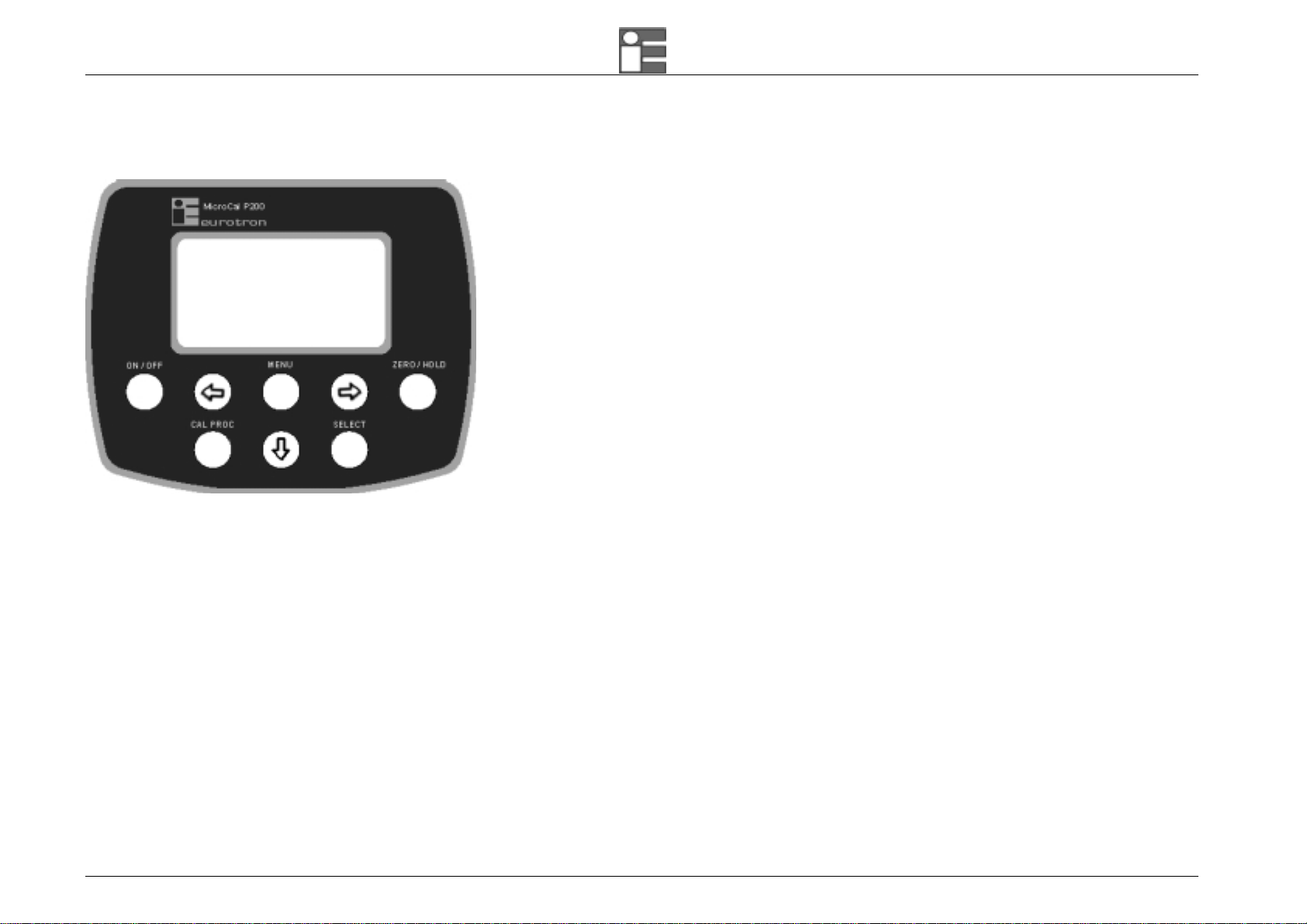
2.1 Keyboard
ON/OFF Switch the instrument on and off.
Arrows 3 keys allows you to move across the menu.
When in output signal mode, to change the electrical
Channel output value.
SELECT enter in channels setup.
MENU Recall setup and configuration menu.
Return in measure mode when in Select menu.
CAL PROC Recall documenting procedures.
HOLD/ZERO Data hold and zeroing the channel.

Instruction Manual MM850470 ed.1a
13
2.2 Display
15.2000
Ch In mA
ChP
Pi
m
b
ar
130.02
The figure shows the features of a typical display. The display shown is in MEASURE and SOURCE mode.
The other parts of the display are as follows:
• Status box: show the operative mode symbols (see the table below).
• Signal value: show the electrical measured value (mV, V, mA, or Pt100), the engineering unit and the input mode.
• Pressure value: show the pressure (internal or external), the engineering unit and the input or the output mode.
Status box
Symbols Description
Battery level:
This animated symbol will show the level of charge of the rechargeable batteries.
H
Data Hold:
This symbol appear on display when the measure are freeze by pressing the [ZERO/HOLD] key.
Z
Zero function:
This symbol appear on display when the [ZERO/HOLD] key is keep pressed for more than 2 seconds. It show that the relative measuring is active.
Instruction Manual MM850470 ed.1a
14
2.3 Power supply
MicroCal P200 can be powered from:
internal rechargeable Ni-MH battery.
External battery charger, supplied as a standard accessory (the batteries must be installed).
The Ni-MH rechargeable batteries allows a long time operation and do not need maintenance. The same batteries power both the instrument and the external pressure modules.
Battery life (typical):
10 h on Tc and mV input/output (backlight Off)
4 h with 20 mA simulation (backlight Off)
Recharging time (typical): 5 h at 90% and 6 h at 99% with instrument switched off.
During operation a fully battery symbol “≠” will be displayed on the display. This symbol means that the batteries are completely full. When the batteries will be discharged the
symbol “–” will appear and the instrument still has about 20 minutes operation capability to end the running analysis.
The battery symbol indicates that a full charge is required. Use only the dedicated battery charger supplied by Eurotron together the instrument.
CAUTION: OLD BATTERIES CAN LEAK AND CAUSE CORROSION. NEVER LEAVE RUN DOWN BATTERIES IN THE INSTRUMENT
WARNING
THE INSTRUMENT IS SHIPPED WITH AN AVERAGE LEVEL OF BATTERY CHARGE. AFTER UNPACKING, A FULL CHARGE OF THE BATTERY IS RECOMMENDED, BY CONNECTING THE INSTRUMENT TO THE
MAIN LINE THROUGH THE BATTERY CHARGER (OFF CONDITION) FOR 8/10 HOURS.
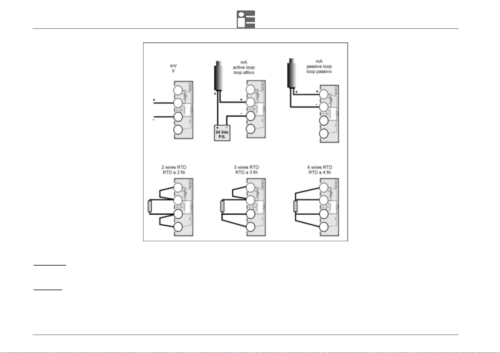
2.4 Electrical connections
MicroCal P200 calibrator is designed to be insensitive to transients or noise, the following recommendations should be followed to reduce ac pick up in the signal leads and to
ensure a good performance. The input leads should not be run near ac line wiring, transformers and heating elements. Input/output leads should, if possible, be twisted and
shielded with the shield grounded at the end of the cable. When shielded cables are used the shield must be connected to the negative terminal.
The following figure shows some examples of input/output wiring of the instrument:
Instruction Manual MM850470 ed.1a
15
For a better understanding of the appropriate connection when using the instrument to simulate current into industrial 2 wire loop please, note the meaning of the terminal used.
Passive loop
This type of connection is to be used when the external loop is not equipped with the loop power supplied. The calibrator can be, as an example, connected directly to a recorder,
controller, etc. with input circuits configured for current measurements.
Active loop
This type of connection must be used when the external loop is equipped with its loop power supplied. The power supply is not required to be disconnected. The loop circuit must
be opened and the calibrator connections are placed in series on the loop.

Instruction Manual MM850470 ed.1a
16
3 GETTING STARTED
3.1 Unpacking
Remove the instrument from its packing case and remove any shipping ties, clamps, or packing materials.
Carefully follow any instructions given on any attached tags.
Inspect the instrument for scratches, dents, damage to case corner etc. which may have occurred during shipment.
If any mechanical damage is noted, report the damage to the shipping carrier and then notify Eurotron directly or its nearest agent, and retain the damaged packaging for
inspection.
A label indicates the model and the serial number of the instrument. Refer to this number for any inquiry for service, spare parts supply or application and technical support
requirements. Eurotron will keep a data base with all information regarding your instrument.
3.2 Charging the battery
Before you use the calibrator for the first time, charge the battery pack for 8/10 hours by connecting the external battery charger.
3.3 Power up
Press the [ON/OFF] key to switch the instrument on and off. The instrument needs some seconds to check the hardware and to run the autocalibration procedure.
3.4 Automatic channel protections
The Microcal P200 unit, is protected against over-voltage and over-current inputs, by firmware and by thermal fuses.
The firmware is designed to automatically set the channel 1 to the maximum impedance input (20 V f.s. range) and to set the channel 2 in off condition.
The thermal fuses do not need replacement when activated. They automatically restore the input channels after some minutes.
IMPORTANT
WHEN THERMAL FUSES ACTIVATE, YOU SHOULD DISCONNECT THE ELECTRICAL CONNECTIONS FROM THE UNIT AND SWITCH THE INSTRUMENT OFF FOR ABOUT 2 MINUTES. THE THERMAL FUSES WILL
BE AUTOMATICALLY RESTORED AND YOU CAN RESUME YOUR WORK.
3.5 Date and time setting
Before you use the calibrator for the first time, adjust the current data and time of the unit.
• Switch the instrument ON by pressing the [ON/OFF] key.

Instruction Manual MM850470 ed.1a
17
• Press the [MENU] key. Enter in configuration mode by highlight “Configuration” option (use the [ª] key) and press the [¨] key.
• Press the [ª] key to highlight the “Date/Time” option. Press the [¨] key.
• Highlight the “DD” option and press the [¨] key to change the current day. Use the [ª] key to input the day. Press the [¨] key to store the value.
• Highlight the “MM” option and press the [¨] key to change the current month. Use the [ª] key to input the month. Press the [¨] key to store the value.
• Highlight the “YY” option and press the [¨] key to change the current year. Use the [ª] key to input the year. Press the [¨] key to store the value.
• Highlight the “hh” option and press the [¨] key to change the current hours. Use the [ª] key to input the hours. Press the [¨] key to store the value.
• Highlight the “mm” option and press the [¨] key to change the current minutes. Use the [ª] key to input the minutes. Press the [¨] key to store the value.
• Press the [MENU] key to return in measuring mode.
3.6 Using the backlight and setting contrast
The backlight is automatically activated by pressing a key. To manually switch on and off the backlight proceed as follows:
• Press the [MENU] key. Enter in configuration mode by highlight “Configuration” option (use the [ª] key) and press the [¨] key.
• Press the [ª] key to highlight the “Display” option. Press the [¨] key.
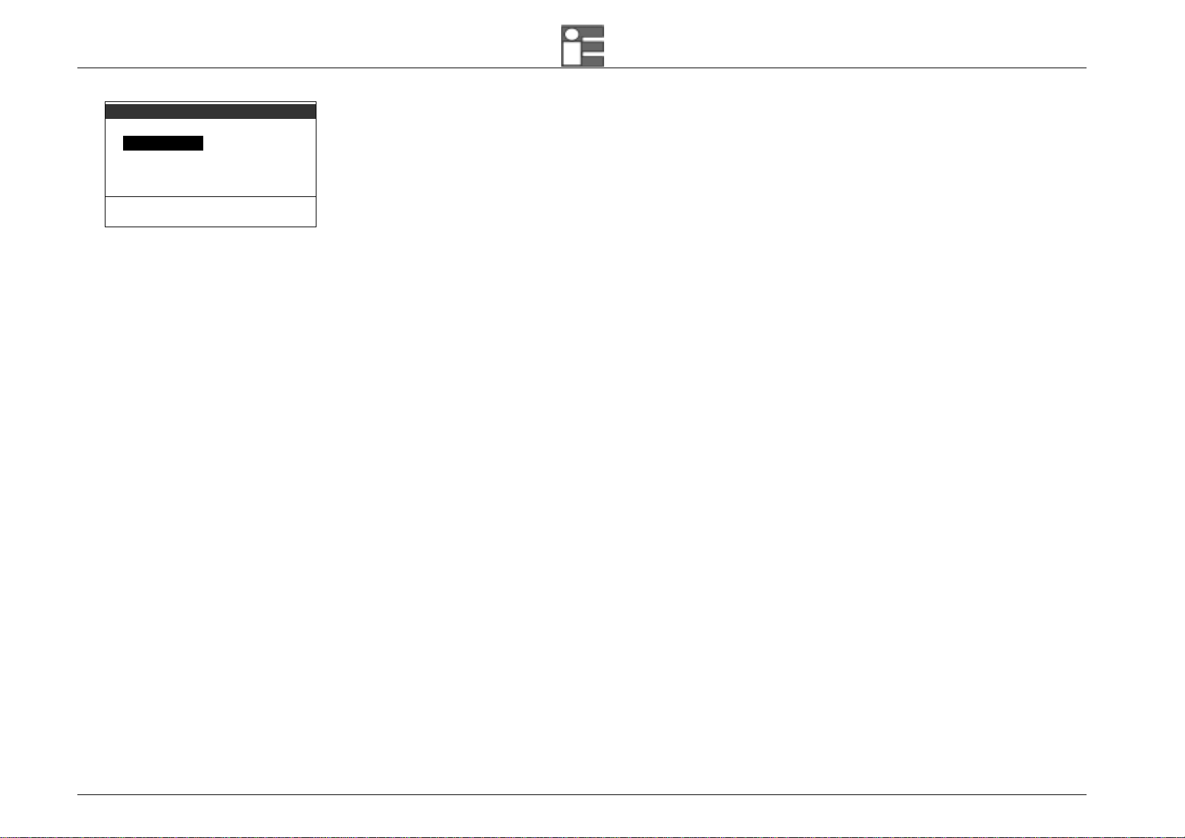
MENU
Configuration
Unit
Data logger
Auxiliary
Display [ChIn&ChP]
Press <¨> to SET
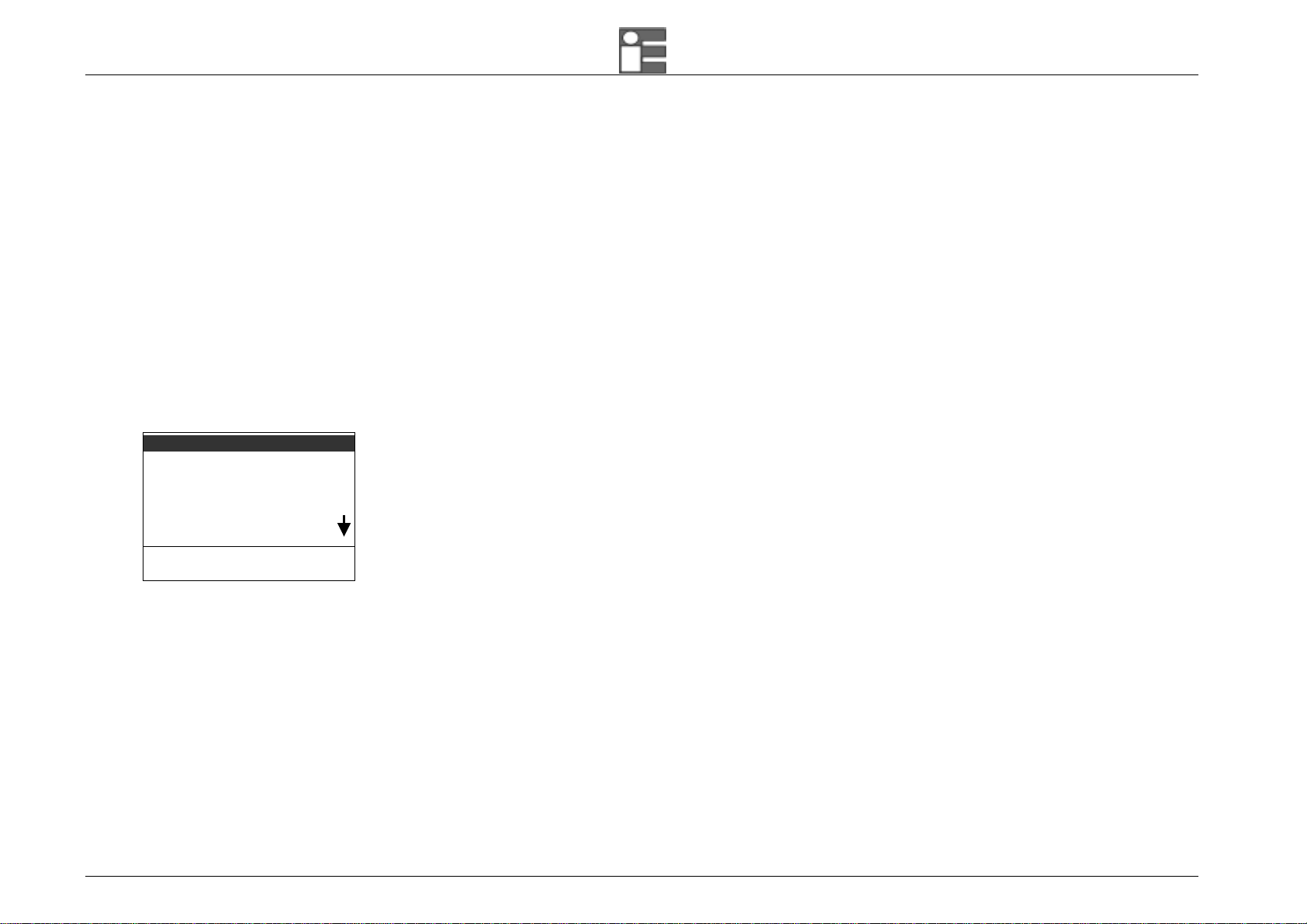
Configuration
Display
Power On [Set Ch]
Date/Time
Rejection [50 Hz]
Baud rate
Press <¨> to SET
Display
Light [On]
Contrast
Press <¨> to SET
• Highlight the “Light” option and press the [¨] key to change the Backlight configuration. Use the [ª] key to highlight the desired function. Press the [¨] key to store the
changes.
• Press [MENU] key to return in measuring mode.
To set the contrast level, select “Contrast” and set it by means of [¨] and [¨].
Instruction Manual MM850470 ed.1a
18
Display
Light [On]
Contrast
Press <¨> to SET confirm the regulation pressing [MENU].
3.7 Data Hold
Press the [HOLD/ZERO] key to freeze the measure. The symbol “H” will displayed in the status box.
Press the [HOLD/ZERO] key to release the measure. The symbol “H” will removed from the status box.
Instruction Manual MM850470 ed.1a
19
4 OPERATIONS
The operating mode (i.e., Source, measure) is shown on the display. Electrical signal channel can Sourcing or Measuring (plus model only) electrical parameter (mA, mV, V,
Pt100). If external pressure sensor is installed, an additional Pressure channel can be shown on the display.
When you turn the calibrator ON, it powers up with the last settings.
Please refers to Chapter 2.4 for electrical connections.
4.1 Measure mode
4.1.1 Pressure
• Press the [SELECT] key until “SELECT Pressure” is shown.
Pi = Internal pressure
Pe = External pressure
Pe-Pi = Differential pressure
• Press the [ª] key to highlight the sensor to be displayed.
• Press the [¨] key to confirm the selection and going in measuring mode. Press the [MENU] key to return in measure mode without changes.
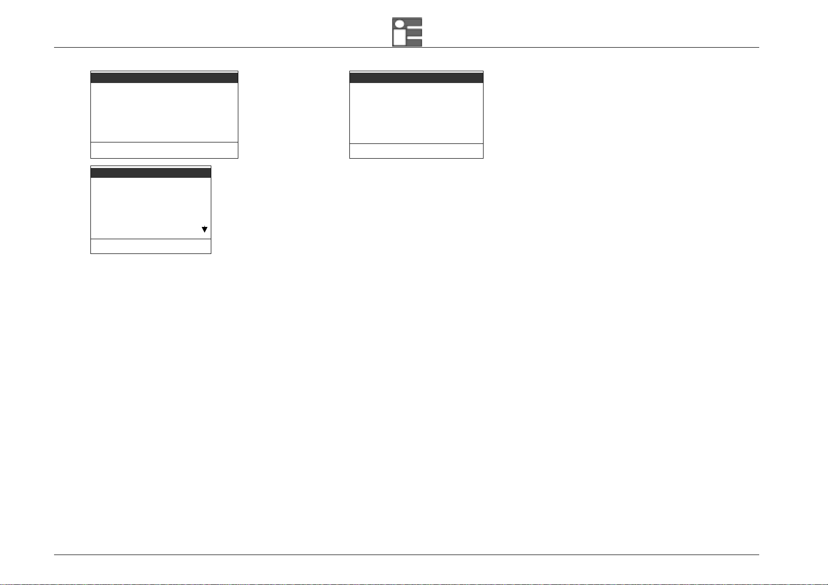
4.1.2 Pressure Unit Setting
• Press the [MENU] key. The following page is shown:
SELECT Pressure
Pi
Pe
Pe-Pi
Press <¨> to SET
Instruction Manual MM850470 ed.1a
20
MENU
Configuration
Unit
Data logger
Auxiliary
Display [ChIn&ChP]
Press <¨> to SET Select the “Unit” option.
Unit
Temperature
Pressure [mbar]
Xscale
Press <¨> to SET Select the “Pressure” option.
Pressure
mbar
bar
Pa
hPa
kPa
Press <¨> to SET
• Press the [ª] key to highlight the engineering unit you would like to use in temperature sourcing and measuring.
• Press the [¨] key to confirm the selection and going in measuring mode. Press the [MENU] key to return in measure mode without changes.
4.1.3 Pressure Zeroing
• To zeroing the pressure channel, hold down the [HOLD/ZERO] key for 4 seconds while in pressure display mode. The “Z” symbol will shown in status box. Switch off and then
on the instrument to disable this function.
4.1.4 Current
MicroCal P200 plus model only can support electrical signal input. See table on Technical Specifications chapter.
• Press the [SELECT] key until “SELECT Ch1” is shown. The calibrator displays:
This manual suits for next models
2
Table of contents


