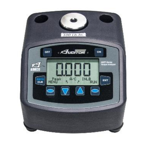
Aimco Auditor TORQUE CUBE User manual

TORQUE CUBE™
OPERATIONS MANUAL

2
WARNING! Read all instructions. Failure to follow all instructions listed below
may result in irreparable damage to the product or injury to the user.
WORK AREA
●Keep work area clean and well lit. Cluttered work areas invite accidents.
●Keep Children and bystanders. away during operation.
Distractions can cause the user to lose control.
ELECTRICAL SAFETY
●Product plugs must match the outlet. Never modify the plug in any way.
Unmodified plug matching outlets will reduce the risk of electrical shock
●Do not expose product to moisture or wet conditions. Water entering the
device will increase the risk of product damage or electrical shock.
●Do not abuse the transformer. Never use the cord for carrying, pulling or
unplugging from the wall outlet. Keep cord away from heat, oil, sharp
edges or moving parts. Damaged or entangled cords increase the risk of
electrical shock.
PERSONAL SAFETY
●Stay alert, observe the task at hand and use common sense when using
product. Do not use when tired or under the influence of drugs, alcohol or
medication.
Amoment of inattention can cause personal injury.
●Use safety equipment.
Always wear eye protection. Safety equipment such
as eye protection will reduce personal injuries.
●Do not overreach. Keep proper footing and balance at all times. This
enables control of the process in unexpected situations.
●Dress properly. Do not wear loose clothing or jewelry. Keep your hair or
gloves away from moving parts. Loose clothing, jewelry or hair can get
caught in moving parts.
SERVICE
●Have your product serviced by aqualified repair person using only
identical replacement parts. This ensures the safety and reliability of the
product is maintained.
GENERAL SAFETY RULES

3
Introduction ................................................................................................. 4
System Specifications ................................................................................... 4
Preparing the ATC for Use .............................................................................. 5
Basic Operation ............................................................................................ 6
Program Menu ........................................................................................... 7-8
Charging the Battery ..................................................................................... 8
Side Panel Input /Output .............................................................................. 9
RS-232
....................................................................................................... 9
Description of Functions in Active Display Mode ........................................... 10
Warranty................................................................................................10–11
The Auditor Torque Cube™is aportable device delivering full featured testing
abilities in a small ultra-portable package.
Once brought to the work area, it is important for accuracy and safety reasons
to securely mount your Auditor Torque Cube™ to the workstation prior to use.
The Auditor Torque Cube™is setup with thru-holes for (3/8" /9 mm) x(4" /100
mm) fastening bolts or screws. During operational use, the Auditor Torque Cube™is
subjected to rotational forces that require 2points of attachment
to
the
work
station
to secure against. Dowel pins of at least 2" /50 mm may also be used at
the work station which
will
then
allow
the
unit
to
be
dropped
onto
and
lifted
off
of
the
pins
for maximum portability.
Included
with
the
product, is
a
vertical
and
horizontal
mounting
template
for
ease of use.
TABLE OF CONTENTS
MOUNTING INSTRUCTIONS

4
Description
Thank you for purchasing an Auditor Torque Cube™tester from AIMCO.You have
chosen a unit that is designed to accomplish awide range of torque testing
applications in the smallest footprint with great value.The Auditor Torque Cube™
features aLCD display,
built in NiMh battery pack for portability, and the ability to
test in 2planes,Vertical and Horizontal. AIMCO’s Auditor Torque Cube™also is
enabled with RS-232 output for use with a serial printer or Windows®PC device.
Dimensions: 3.125" /79.375 mm Wide
3.75" /95.25 mm High
3.23" /82.55 mm Deep
2.5 lb /1.13 kg
Power Requirements: 9-26V DC, 150 mA min
Supplied by 100-220VAC Input Transformer
Battery: Internal (non-field serviceable) NiMh pack
32°F/0° Cto 122°F/50°C
Data Communications: RS-232
Accuracy: 1% of Indicated Reading within top
90% of Full Scale
Range: 10% to 100% of Full Scale
Display: 4Active Digits
Units of Measure: Eight (8) Selectable Engineering Units:
In.Oz., In.Lb., Ft.Lb., Nm, CNm, KgfCm, gfCm, Kgfm
Frequency Filter: Selectable filtering frequencies:
125Hz, 250Hz, 500Hz, 750Hz, 1500Hz
INTRODUCTION
SYSTEM SPECIFICATIONS

5
The ATC testers feature asupplied Joint Simulator (Fig.A) that is configurable to a
wide variety of joint conditions. The Joint Simulator is made up of aseries of
Bellville Washers that allow the user to pre-configure the joint to match the actual
application joint as closely as possible.
Each of the Bellville Washers is concave
in shape.
By aligning all the concave curves in the same direction asimulated
hard joint is achieved (Fig. B). Alignment
of
the
concave
shapes
in
an
opposing
manner
a
simulated
soft
joint
is achieved (Fig. C). Differing combinations allow
for simulated medium joints to be achieved (Fig. D).
Fig. A
Fig. B Fig. C Fig. D
Prior to use, remove the Joint Simulator from its bag. Loosen the Hex Screw and
stack the Bellville Washers according to your joint condition needs. Hand thread
the Hex Screw into the housing several threads. Place the square drive end of
the simulator into the female square drive on the ATC Tester.
PREPARING THE ATC FOR USE

6
Power ON and OFF
Pressing any key (CLR, MDE, ENG, ENT) turns unit power ON.
Pressing CLR &ENT simultaneously turns unit power O F F.
CLR
Pressing CLR clears the current reading or zeros the transducer if no reading is
current.
MDE
Pressing MDE will display the current mode for a1second period of time.The unit
will revert to ACTIVE DISPLAY mode after that time. Depressing the MDE key a
second time will scroll through the list of MODES available:
PK, AC 1PK, AC CAL TRACK
Depressing any other key will return the unit to ACTIVE DISPLAY mode. See page 9
for more descriptions.
ENG
Pressing ENG will display the current Unit of measure for a1second period.
Pressing ENG while the Units of Measure are displayed will scroll through the
available units (Kgf M, Kgf Cm, gf Cm, Ncm, Nm, FT LB, IN LB, IN OZ). Pressing any
other key will return to SAMPLE mode.
ENT
Pressing ENT will send the current reading to the serial port and clears the screen.
MDE &ENG
Pressing MDE &ENG buttons simultaneously displays the Program Menu. See
Program Menu section for details.
ACTIVE DISPLAY
Active Display Mode is the normal operating mode used by the Auditor Torque Cube™
for measurement. When ameasurement is taken, the transducer reading or peak is
displayed for the length of time set by Auto Clear (see Program Menu). If High and Low
limits have been preset (see Program Menu) then the LED light will show Green for
a sample within the limits, or Red for one that is outside the preset limits. In Peak and
1
st
Peak modes, the LED will illuminate Green upon completion of the reading if no
limits are preset in the unit. No LED illumination will occur during Track mode.
BASIC OPERATION

7
Buttons for Menu Navigation
ENG -
Functions as an UP button in this
menu. Pressing ENG sequentially
advances the menu to the next
item.
MDE -
Functions as aDOWN button in this
menu. Pressing MDE sequentially
advances the menu to the previous
item.
CLR -Pressing CLR will exit from the
PROGRAM MENU and return the
unit to ACTIVE DISPLAY MODE.
ENT -
Pressing ENT will change the
current item as advanced to or
displayed in the PROGRAM MENU
AC
Auto Clear is time, in seconds 1-9 and
off. When AC is displayed, pressing ENT
will sequentially advance the time
increment by 1second at each press of
ENT. After 5 seconds of no changes, the
unit will revert to Active Display Mode and
the last shown setting will be held. Setting
OFF will deactivate the Auto Clear function
and readings will need to be cleared from
the screen manually using the CLR key.
FILT
Peak filter frequency response in Hz.
Options of 125, 250, 500, 750 and
1500 are available. Press ENT key to
sequentially scroll thru these options.
After 5seconds of no changes, the unit
will revert to Active Display Mode and
the last shown setting will be held.
PPER (PEAK BLANKING)
Minimum peak as apercentage of full
scale. Readings below the SET value will
not be displayed. Settings in the range of
2%-50% are available. Pressing ENT will
sequentially increase the %by one with
each press. At 50% the unit will scroll
back to 2% with the next press of ENT.
After 5seconds of no changes, the unit
will revert to Active Display Mode and the
last shown setting will be held.
SL
Sign Lock. Options of ON or OFF are
available. Press ENT to scroll between the
selections.After 5seconds of no changes,
the unit will revert to Sample Mode and
the last shown setting will be held.
LOW
Lower limit target. Asetting of 0.000
disables the limit. Press ENT to enter
the Number Edit Mode.
The current digit or decimal point
flashes.The Number Edit Mode will
remain active without time out until the
CLR button is pressed.
Press ENG to sequentially increase the
flashing digit. Press MDE to sequentially
decrease the flashing digit. Press ENT to
save the digit and move on to the next.
Once all digits have been adjusted/
entered the decimal point is able to be
moved. ENG will then move the decimal
one position to the right with each press.
MDE will move the decimal point one
position to the left with each press. Press
PROGRAM MENU

8
ENT to exit the Number Edit Mode and
save the number displayed.
HIGH
High limit target.A setting of 0.000
disables the limit.
Press ENT to enter the
Number Edit Mode.
The current digit or decimal point
flashes. Number Edit Mode will remain
active without time out until CLR button
is pressed.
Press ENG to sequentially increase the
flashing digit. Press MDE to sequentially
decrease the flashing digit. Press ENT to
save the digit and move on to the next.
Once all digits have been
adjusted/entered the decimal point is
able to be moved. ENT will then move the
decimal one position to the right with
each press. MDE will move the decimal
point one position to the left with each
press. Press ENT to exit the Number Edit
Mode and save the number displayed.
FS
Full Scale in the current Units of
Measure.This is not editable by the user.
SLEEP
Sleep is used to conserve battery
power. Settings are OFF and from 1-20
seconds. Press ENT to sequentially
scroll through from OFF to the
sequential numbers 1-20. Pressing
ENT at the number 20 scrolls the
menu selection back to O F F.
After 5
seconds of no changes, the unit will
revert to Active Display Mode and the
last shown setting will be held.
The internal battery pack contained in
the Auditor Torque Cube™is non-user
serviceable. When treated properly, the
battery pack should provide
approximately 12 hours of continuous
use from afull charge.
The battery chemistry contained within
the Auditor Torque Cube™ is NiMh and
charges with the supplied power
transformer. Any time the Auditor Torque
Cube™ is plugged in, the batteries are
trickle charged at arate that takes
approximately 8hours for afull charge.
There is no indication to the user that the
unit is charging and it is recommended to
simply leave the unit charging at anytime
it is not in use.There is no harm in leaving
the charger connected and this will
actually improve battery life.
If the Auditor Torque Cube™ is going to
be stored for alengthy period of time, it
is recommend to charge the battery prior
to doing so. Also note, the unit should be
checked and charged on abi-monthly
basis to insure that the batteries remain
in achargeable condition.
CHARGING THE BATTERY

9
When viewing the Auditor Torque
Cube™from the operators
perspective, there are 2 connectors on
the left side of the unit.
DC IN
The interface for the AC Adapter that
was supplied with the unit is the upper
connector.This connection may be used
when the unit is charging or during
operation.
Use only the supplied Auditor
Torque Cube™AC Adapter with this
unit. Use of any other adapter may
cause damage to the unit.
RS-232
The lower connector is for an RS-232
(P/N RS232) cable enabling
connection to aseRial printer, data
collector, computer or other RS-232
enabled device.Values are sent via RS-
232 each time the unit Auto Clears
(AC) or the ENT or CLR buttons are
pressed.
RS-232 Transfer Protocol
Protocol Value
Cable P/N RS232C Mini-Plug
(Auditor CUBE) –Dsub 9
Pin
Baud Rate 9600
Parity None
Bits 8
Stop Bit 1
Flow None
RS-232 Data Stream Format
Mmmbsdddddbuuuuucl where:
m=Memory Location
b
=Blank
s
=Sign (Space or -)
d
=Data with Decimal Point
u
=Units
c
=Carriage Return
l
=Line Feed
RS-232 Cable Pinouts
Pin# Description
1Unused
2Transmit
3Receive
4Unused
5Ground
6Unused
7Unused
8Unused
9Unused
SIDE PANEL INPUT / OUTPUT
RS-232

10
PEAK
Displays and retains the maximum torque
exerted by the tool or wrench as occurring
in the tightening direction.The peak mode
is used for power tools and some dial
wrenches.
1st Peak
Detects the “first peak” of torque
exerted by the wrench as experienced
by the Auditor Torque Cube™when the
wrench cams or clicks over its set
torque level. First peak is used
primarily for click-type torque wrenches
and torque-limiting screwdrivers.
TRACK
Displays torque as it is directly applied
to the Auditor Torque Cube’s sensor.
ENGINEERING UNITS
8Possible Units of Measure are available
with the Auditor Torque Cube: In.Oz., In.Lb.,
Ft.Lb., Nm, CNm, KgfCm, gfCm, Kgfm
FULL SCALE
The FS screen shows the Full Scale value
of the Auditor Torque Cube™ sensor.This
is not a field adjustable value.
LOW LIMIT
Use the Low Limit setting as ameans
of visually alerting the operator when a
reading fails to reach adesired
minimum value.The RED LED will
illuminate to let the operator know that
the achieved reading was below the
preset level.
HIGH LIMIT
Use the High Limit setting as ameans
of visually alerting the operator when a
reading is above adesired maximum
value.The RED LED will illuminate to let
the operator know that the achieved
reading was above the preset level.
CAL
For factory authorized service center
use only.
NEW TOOL AND ACCESSORY WARRANTY
Any new tool or accessory branded with the AIMCO,Uryu,AcraDyne or Eagle Industries name,and
purchased from AIMCO,or through one of its authorized distributors or agents,is warranted to
the original buyer against defects in materials and workmanship for aperiod of one (1) year*
from date of delivery. Under the terms of this warranty,AIMCO will repair or replace any product
or accessory warranted hereunder and returned freight prepaid proving to AIMCO’s satisfaction
to be defective as aresult of workmanship or materials. In order to qualify for this warranty,
written notice to AIMCO must be given immediately upon discovery of such defect, at which
time AIMCO will issue an authorization to return the tool.The defective item must be promptly
returned to an authorized AIMCO service center with all freight charges prepaid.
DESCRIPTION OF FUNCTIONS IN ACTIVE DISPLAY
WARRANTY

11
REPAIRED TOOL WARRANTY
Once atool is beyond the new product warranty period as detailed above,AIMCO repairs are
subject to the following warranty periods:pneumatic tools:90 days*; electric tools and Acra-
Feed:90 days; battery tools:30 days*; DC Electric tools: 90 days*
EXCLUSION FROM WARRANTY
This warranty is valid only on products purchased from AIMCO, or thru its authorized distributors
or agents. AIMCO shall have no obligation pursuant to the AIMCO Warranty with respect to any
tools or accessories which in AIMCO’s sole judgment have been altered, damaged, misused,
abused, badly worn, lost or improperly maintained.This Warranty is null and void if the customer,
or any other person other than an authorized representative of AIMCO, has made any attempt to
service or modify the tool or accessory prior to its return to AIMCO under this Warranty.
The warranty provision with respect to each such product may be amended by AIMCO from
time to time in its sole discretion.The liability of AIMCO hereunder shall be limited to replacing
or repairing,at its option,any products which are returned freight prepaid to AIMCO and which
AIMCO determines to be defective as described above or, at AIMCO’s option, refunding the
purchase price of such products.
AIMCO reserves the right to make periodic changes in construction or tool design at any
time.AIMCO specifically reserves the right to make these changes without incurring any
obligation or incorporating such changes or updates in tools or parts previously distributed.
THE AIMCO WARRANTY IS IN LIEU OF ALL OTHER WARRANTIES,EXPRESSED OR IMPLIED,AND
AIMCO EXPRESSLY DISCLAIMS ANY WARRANTY OF MERCHANTABILITY OR FITNESS FOR A
PARTICULAR PURPOSE.THIS WARRANTY SETS FORTH THE SOLE AND EXCLUSIVE REMEDY IN
CONTRACT,TORT, STRICT LIABILITY, OR OTHERWISE.
THIS WARRANTY IS THE ONLY WARRANTY MADE BY AIMCO WITH RESPECT TO THE GOODS
DELIVERED HEREUNDER, AND MAY BE MODIFIED OR AMENDED ONLY BY AWRITTEN
INSTRUMENT SIGNED BY ADULY AUTHORIZED OFFICER OF AIMCO.
LIMITATION OF LIABILITY
AIMCO’S LIABILITY PURSUANT TO WARRANTY OF THE PRODUCTS COVERED HEREUNDER IS
LIMITED TO REFUND OF THE PURCHASE PRICE. IN NO EVENT SHALL AIMCO BE LIABLE FOR
COSTS OF PROCUREMENT OF SUBSTITUTE GOODS BY THE BUYER. IN NO EVENT SHALL AIMCO
BE LIABLE FOR ANY SPECIAL, CONSEQUENTIAL, INCIDENTAL OR OTHER DAMAGES
(INCLUDING WITHOUT LIMITATION, LOSS OF PROFIT) WHETHER FOR BREACH OR REPUDIATION
OF CONTRACT, BREACH OF WARRANTY, NEGLIGENCE OR OTHERWISE.THIS EXCLUSION ALSO
INCLUDES AND LIABILITY WHICH MAY ARISE OUT OFTHIRD PARTY CLAIMS AGAINST BUYER.THE
ESSENTIAL PURPOSE OF THIS PROVISION IS TO LIMIT THE POTENTIAL LIABILITY OF AIMCO
ARISING OUT OF THE AGREEMENT AND/OR SALE.
Note: The AIMCO Warranty confers specific legal rights, however some states or jurisdictions
may not allow certain exclusions or limitations within the warranty.
*All warranty periods addressed herein are determined using astandard shift, eight-hour work day.

12
AIMCO CORPORATE HEADQUARTERS AIMCO CORPORATION DE MEXICO SA DE CV
10000 SE Pine Street Ave. Cristobal Colon 14529
Portland, Oregon 97216 Chihuahua, Chihuahua. 31125
Phone: (503) 254–6600 Mexico
Toll Free: 1-800-852-1368 Phone: (01-614) 380-1010
Fax: (01-614) 380-1019
LIT-MAN920 Rev. 07/2020
Printed in USA ©2020 AIMCO
Table of contents
Other Aimco Test Equipment manuals
Popular Test Equipment manuals by other brands

BIRD
BIRD FlightHawk Operation manual

NOVOTEST
NOVOTEST T-UD2 operating manual

Alps Electric
Alps Electric SPEEDGLIDER installation manual

Keysight Technologies
Keysight Technologies U3042AM04 User's and service guide

Softing
Softing PROFIBUS Tester 4 BC-600-PB manual

GW Instek
GW Instek GDS-3000 Series user manual