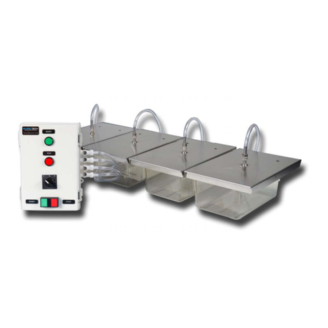
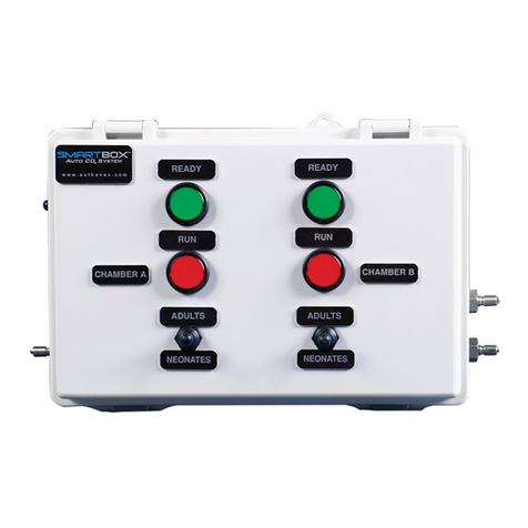
EUTHANEX SMARTBOX EA-32000 User manual

1
Auto CO2Lab Control Unit
Model – EA-32000
1-877-559-0159 Toll Free Euthanex Corp. / E-Z Systems
1-610-882-3801 Fax P.O. Box 3544
www.ezsystemsinc.com Palmer, PA 18043

2
Table of Contents
Disclaimer and Lab Control Unit
Overview …………………………………………………………………………….3
Safety Instructions……………………………………………………………………4
System Set-Up..………………………………………………………………………5
Operating the System…………………………………………………………………8
Changing System Presets…..…………………………………………………………9
Flow Rate & Preset Times …………..………………………………………………11
EMC / EMI.
This equipment has been tested and found to
comply with the limits for a Class A Equipment,
pursuant to part 15 of the FCC rules.
IEC 61326-1:2005 / EZ 61326-1:2006
For the customers in Canada:
This Class A Equipment complies with
Canadian ICES-003:2012.
Cet appareil numérique de la classe A est
conforme à la norme NMB-003:2012 du Canada.

3
THIS MANUAL MUST BE READ BEFORE SETTING UP AND OPERATING
THE SMARTBOX AUTO CO2SYSTEM. The user should be thoroughly familiar with
the contents of this manual prior to using the system with animals. Only technicians that
are properly certified should operate the system.
The user/owner of this equipment shall have the sole responsibility for any damage or
injury resulting from operation that is not in accordance with the authorized instructions.
This includes, but is not limited to, operating the equipment outside of recommended
safety levels, variation from specified operating instructions, and not following standard
laboratory safety procedures when working with anesthetic agents and volatile
compressed gases.
The system and its components must only be modified or repaired by Euthanex
authorized service technicians. Improper modification or repair may result in danger to
personnel, harm or death to animal, and/or equipment damage. The user/owner of this
equipment shall have the sole responsibility for any damage or injury resulting from
improper maintenance and repair that is not done by authorized maintenance and repair
personnel.
Parts that have failed, in whole or in part, exhibit excessive wear, are contaminated or are
otherwise at the end of their useful life, should not be used and should be replaced with
parts supplied by Euthanex Corporation. Tampering with the main control unit by
unauthorized personnel automatically voids all warranties and specifications. The
manufacturer assumes no responsibility for any malfunction or failure of the unit if
tampering is suspected.
Overview:
The Lab Control Unit utilizes a programmable logic controller (PLC) that delivers a set
volume of CO2into an individual animal cage through the Euthanex Lid. The controller
unit operates at a fixed flow rate that is set at your external CO2source. Gas flows from
the external source into the Lab Control Unit. A solenoid valve opens to output gas to the
Euthanex Lid. After the euthanasia cycle is completed, the Lab Control Unit
automatically shuts the gas off.
The EA-31000 model treats a single cage or chamber.
The Lab Control Unit comes with one preset gas delivery timing. The EA-31000 offers a
single programmable timing. It is highly recommended that only designated, trained
personnel make adjustments to the timings, to ensure safe and effective settings.
Please refer to the “Flow Rate & Preset Times” section to derive the AVMA
recommended flow rate.

4
The lightning flash with an arrowhead
symbol within an equilateral triangle, is
intended to alert the user to the presence of
uninsulated "dangerous voltage" within the
product's enclosure that may be of sufficient
magnitude to constitute a risk of electric shock to
persons.
1. Read these instructions.
2. Keep these instructions.
3. Heed all warnings.
4. Follow all instructions.
5. Do not use this unit near water.
6. Do not clean by spraying liquid directly onto
unit.
7. Do not block any ventilation openings.
Install in accordance with the manufacturer's
instructions.
8. Do not install near any heat sources such
as radiators, heat registers, stoves, or other
unit that produce heat.
9. Do not defeat the safety purpose of the
polarized or grounding-type plug. A
polarized plug has two blades with one
wider than the other. A grounding type plug
has two blades and a third grounding
prong. The wide blade or the third prong
are provided for your safety. If the provided
plug does not fit into your outlet, consult an
electrician for replacement of the obsolete
outlet.
10. Protect the power cord from being walked
on or pinched particularly at plugs,
convenience receptacles, and the point
where they exit from the unit.
11. Unplug this unit during lightning
storms or when unused for long periods of
time.
12. Refer all servicing to qualified service
personnel. Servicing is required when the
unit has been damaged in any way,
such as power-supply cord or plug is
damaged, liquid has been spilled or objects
have fallen into the unit, the
unit has been exposed to rain or
moisture, does not operate normally, or has
been dropped.
The exclamation point within an equilateral triangle is
intended to alert the user to the presence of important
operating and maintenance (servicing) instructions in
the literature accompanying the product.
Warning!
To reduce the risk of fire or electric shock,
do not expose this unit to rain or
moisture.
Use line cord supplied with the product.
Be advised that different operating voltages
require the use of different types of line
cord and attachment plugs. The unit was
shipped with the requested plug. If the
installation requirements change please
contact us for the correct plug.
This equipment should be installed near the
socket outlet and disconnection of the device
should be easily accessible.
Do not install in a confined space.
Do not open the unit - risk of electric shock
inside.
Caution: You are cautioned that any change or
modifications not expressly approved in this
manual could void your authority to operate
this equipment.
Service
There are no user-serviceable parts inside.
All service must be performed by qualified
personnel.
Voltage 100-240 v ac 50-60hz 1 amp Max (auto
select)
Pressure 75 psi max to inlet
Temp 0 to 40°C <> 10 to 85% RH (no
condensation)

5
System Set-Up:
1. Four mounting brackets are utilized to secure the controller unit to the wall. These are
on the controller when shipped.
2. Using a Phillips head screwdriver, loosen the screws and move the mount tabs outward
as pictured below. Tighten the screws once appropriate position is achieved.

6
3. With the mounting brackets moved, position the unit in the appropriate location on the
wall and mark the four holes. Remove unit from wall and drill the holes. Secure the unit
to the wall with appropriate screws. (Wall screws are not included.)
4. Connect the external CO2gas line from the regulator or flow meter, to the gas input of
the Lab Control Unit. Check the Flow Rate Guide to determine the correct LPM settings.

7
5. Connect the supplied cage hose from the output of the Lab Control Unit to the input
valve on the Euthanex Lid. To properly make the connection, pull back the coupler and
slide it over the male stem. The coupler will snap back into place and secure the
connection.
GAS WILL NOT FLOW INTO LID IF THE COUPLER IS NOT PROPERLY
ATTACHED.
6. Place the Euthanex Lid on the cage, and the system is ready for operation.

8
Operating the Lab Control Unit:
1. Be sure CO2source is open, and the regulator/flow-meter is set to the correct flow rate.
2. Move the rocker on/off button located on the bottom of the unit to the “On” position.
The green “Ready” light will turn on.
3. The EA-32000 offers two distinct timing choices. Select the desired timing cycle by
moving the toggle switch either up or down.
4. To begin the euthanasia cycle, press the toggle toward the desired species.
The red “Run” light will turn on, indicating that the cycle is operating.
When the cycle is complete, the red light will shut off and the gas flow will stop.
The green “Ready” light will turn on, indicating the cycle is complete and the
system is ready to run the next cycle.
Start
Toggle

9
Changing the System Presets:
Before any service is done that would require opening the unit it must be
disconnected from the power source. If your location has lockout-
tagout protocols please follow them.
Preset times were determined based on extensive testing done by Euthanex Corp. and
designed to comply with the latest guidelines of the AVMA Panel on Euthanasia. Refer
to the Flow Rate to determine AVMA compliant flow rates and the timing presets. The
following is the procedure for changing the preset times:
1. Release the two latches to open the controller door.
2. The start-up screen will appear on the PLC.
3. To change the preset cycle times, press “ESC”. The option screen will appear.
4. Press the down button to move the arrow to: “> Set Param”. Press “OK”.

10
5. “Timer 1” screen will appear.
Press “OK” and the first number will begin to flash.
Use the Up/Down keys to increase or decrease the value.
Use the Right/Left keys to move the cursor to the number you would like to
change.
After the proper time is set, press “OK”.
Note: Only the T = 00:00m will be set. The Ta = 00:00 is not a programmable function.
6. The EA-32000 offers two programmable timer settings. Press the Up/Down keys to
navigate the timer choices. When the desired timer appears, repeat step five to change the
time.
7. After settings the timers, press the “ESC” button twice to return to the opening screen.
The Lab Control Unit is now ready to operate. Close and latch the door.

11
F series IDEC or Siemens:
1. Release the two latches to open the controller door.
2. The clock screen is on the PLC.
3. To change the preset cycle times, press ESC, then OK. The option screen will appear.
4. Press the down button , to move the arrow to: “> Program”. Press OK.
5. Press the down button , to move the arrow to: “> Set Parameter”. Press OK.
6. The password screen appears. Use the up/dw and Rt/Lt arrow to input password
"CLUTCH" then hit OK

12
6. Timer select screen appears. This screen is maybe different that the picture based on
the program loaded.
* Use the up/down keys to move to the value to change.
* Press “OK” and the screen will change. Press the right arrow until s large box
will be over the timer.
* Press “OK” and the box will become small and over the first value of the timer.
* Use the right/left keys to move the cursor to the number you would like to
change.
* Use the up/down keys to increase or decrease the value.
* Use the right/left keys to move the cursor to the number you would like to
change.
* After the proper time is set, press OK. The box will change back to large.
Note: only the T = 00:00m will be set. The Ta = 00:00 is not a programmable function.

13
6. After setting the timers, press the “ESC” button to return to the main screen.
Use the up key to move to start, hit "OK" button, use left arrow to move to Yes, Hit "OK"
button.
The Lab Control Unit is now ready to operate. Close and latch the door.
Flow Rate & Preset Times:
Default times were chosen to comply with the latest guidelines of the AVMA Panel
on Euthanasia and through extensive testing performed by Euthanex Corp. Times are
customizable to facility needs. The programmable times may be changed by a
designated administrator.
Preset Times: The units are pre-programed for Adult and Neonates unless
otherwise request at time of order.
Position 1 (Adult) = 5 minutes
Dwell = 5 minutes
Position 2 (Neonate) = 7 minutes
Dwell = 60 minutes
How to derive AVMA compliant flow rate from chamber size (for a single chamber):
Height(in) x Width(in) x Length(in)= Liters x 20% = flow rate
61
The 2013 AVMA Euthanasia Guidelines recommend 10 – 30% fill rate.
Other EUTHANEX Control Unit manuals
Popular Control Unit manuals by other brands
Nice
Nice IBT4ZWAVE Instructions and warnings for installation and use
King gates
King gates Star B plus quick start guide

Samson
Samson 41-23 Series Mounting and operating instructions
Dormakaba
Dormakaba UNIQUIN Mounting instructions
PEHA
PEHA 942 STM AN Installation Instructions and Quick Guide
BENDIX
BENDIX R-6 RELAY VALVE manual

DM Engineering
DM Engineering Mic Pro user guide
L&L
L&L TLR04M-350-700 installation instructions
QTS
QTS Level-Trac LT-310 Installation, operation and instruction manual
Akerstroms
Akerstroms Trux 700 user manual
Kintech Engineering
Kintech Engineering BGAN Installation & antenna orientation
Allen-Bradley
Allen-Bradley 1794-VHSC user manual
