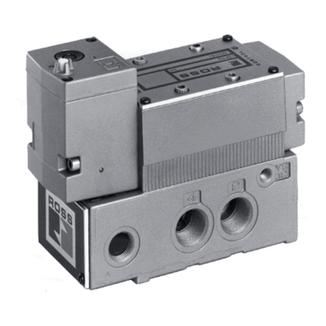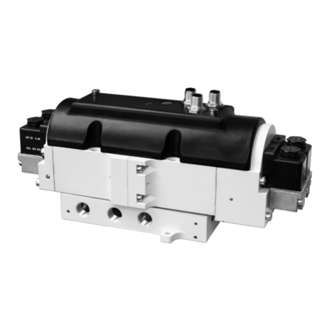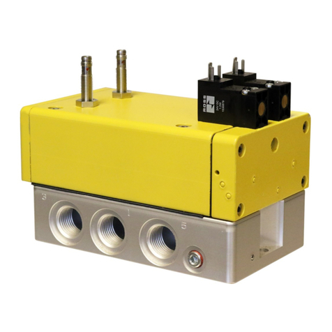
HBB Series Operating Instructions
4www.rosscontrols.com
4
provides a diagnostic coverage of up to 99%. Monitoring of these switches must be
done by an external monitoring system.
The unit cannot be used by itself. It is designed for installation in a machine. ROSS
and its suppliers will assume no liability in the event that the system or parts thereof
are not used in accordance with their designated use or if modications are made in
a non-authorized manner.
Any drawings, hydraulic or electric circuit diagrams, parts lists and acceptance
certicates (inspection reports) supplied do not form a part of these operating
instructions. They are supplied for the purpose of illustrating the unit or procuring parts.
2.1.1. Safety Function According to ISO 13849
HBB Series Block and Bleed systems are designed in accordance with the requirements
listed in ISO 13849-1 and -2. Their “fail-to-safe” safety function is ensured even in case
of a fault within the valve (e.g., caused by power loss, wear, contamination, or similar
situations).
The safety function of the HBB Series Block and Bleed system is to only supply ow
and pressure into the machine/system when the two valve elements are actuated
simultaneously, but to shut-off the supply and to bleed the downstream pressure
back to tank when both valves are shut off or if only one of the two valves is de-
actuated.
A fault in the system where only one valve actuates when switching on or only one
de-actuates when switching off prevents ow of hydraulic uid from being supplied
downstream. Monitoring of the two inductive position switches by the user’s external
safety control & monitoring system makes it possible to detect these fault situations
and to shut off and prevent further electrical energization of the solenoids until the
fault is cleared.
Port identication on the manifold according to ISO 16874
The HBB Series Block and Bleed system is designed and manufactured in accordance
with the identication requirements laid out in the ISO 16874:2004 standard.
2.1.2. Common Cause Failure – CCF
The product has been engineered and manufactured according to the fundamental
and proven safety principles of ISO 13849-1 and -2.
Common Cause Failures (CCF) are failures of different components, resulting from
a single event. CCF are not to be confused with cascading faults or common mode
faults. Common cause failures can cause loss of the safety function, especially in dual
channel circuits where both channels could fail simultaneously due to a single event.
• Maintain hydraulic uid quality, i.e., proper ltration.
• Operate within prescribed temperature limits.
• Install the valve such that the normal stroke travel of the valve elements is
perpendicular to the main direction of machine vibration and/or mechanical shock.
• Avoid external magnetic elds.
• Do not use a test pulse longer than suggested in the Integration Guide.
• Do not plug the T port or Y port (where provided). These ports should be piped to
the reservoir.
2.1.3. Diagnostic Coverage
A diagnostic coverage of 99% is achievable through appropriate integration of the
HBB Series Block and Bleed system into the safety control system. The monitoring
system must constantly compare the state of each valve’s inductive position switch
(Switch 2A & Switch 3A) with the state of the safety control system outputs to the valve
solenoids (Sol 2A & Sol 3A). Detection of a fault by the safety control & monitoring
system must trigger a shut-off of the safety controller’s outputs to the valve solenoids
(Sol 2A & Sol 3A).
2.1.4. Fault Modes
Note that normal operation requires that Sol 2A & Sol 3A be energized simultaneously
for switching the HBB Series Block and Bleed system on, and de-energizing both Sol
2A and Sol 3A simultaneously for switching the HBB Series Block and Bleed system off.
NOTE: The switches are supplied with both NC and NO contacts. The statements
below only refer to whether or not the switches are actuated.
Faults that could occur during normal operation are:
Sol 2A & Sol 3A energized simultaneously
Switch 2A ON, Switch 3A OFF
Switch 2A OFF, Switch 3A ON
Switch 2A OFF, Switch 3A OFF
Sol 2A & Sol 3A de-energized simultaneously
Switch 2A ON, Switch 3A OFF
Switch 2A OFF, Switch 3A ON
Switch 2A ON, Switch 3A ON
1. About this Documentation
These instructions contain important information for the safe and appropriate assembly
and commissioning of the product.
fRead these Instructions all the way through, particularly section 6 “Safety
instructions,” before working with the product.
For more information see last page for contact information, or visit www.rosscontrols.com.
fIn addition, observe all applicable local and national regulations on accident
prevention and on environmental protection.
1.1. Warning Notices in these Operating Instructions
In these operating instructions, warning notices precede sections with handling
requirements which incur risks of personal injury or material damage.
Warnings are structured as follows:
SIGNAL WORD
Type or source of hazard!
Consequences
fMeasures to avert danger
• Warning triangle: Indicates a risk of fatal or severe injuries.
• Signal word: Indicates the severity of the danger.
• Type or source of hazard: States the type of danger or the source of the hazard.
• Consequences: Describes possible consequences of ignoring the warning.
• Measures to avert danger:Indicates how to avoid the danger. It is essential that
the measures to avert danger are complied with.
DANGER
Indicates an imminent and serious danger that will result in severe or
even fatal injury if you fail to avoid it.
WARNING
Indicates a possible danger that could result in severe or even fatal
injury if you fail to avoid it.
CAUTION
Indicates a danger that may result in minor to moderate injuries if
you fail to avoid it.
ATTENTION
Indicates potential property damage that may be incurred by the
product or its surroundings if you fail to avoid it.
2. Notes on Safety
The product has been manufactured according to the accepted rules of current
technology. There is risk of injury or damage if the following safety instructions and
warnings given in this instruction manual are not observed.
2.1. Intended Use
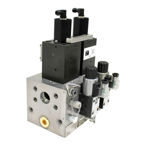
The HBB Series Block and Bleed Control systems are safety components designed and
manufactured in accordance with Machinery Directive 2006/42/EC.
The HBB system is comprised of two single valves (direct solenoid-operated spool
valves on D03 and D05 sizes & solenoid pilot-operated valves on D07 size) which make
it a redundant design for meeting the needs and requirements of safe hydraulic block
and bleed applications. Typically, these systems are designed to meet Category 4, PL e,
SIL 3 applications if properly implemented into the safety control & monitoring system.
The HBB Series Block and Bleed system is designed to allow the ow of hydraulic uid
into a hydraulic system and to block that ow and simultaneously bleed downstream
energy when needed.
NOTE: Block and Bleed functions are intended to permit ow when switched on
and to block supply and to bleed off downstream energy when switched off or in a
faulted state. It is important to note that the ability to bleed may be affected by other
components downstream of the HBB valve. PO checks, counterbalance, and closed-
center valves are designed to block ow under certain conditions. Depending on the
application, these devices may be detrimental or they may be benecial to complete
the needed safety function. Careful consideration of the required safety function and
how to achieve that goal is absolutely necessary.
NOTE: HBB valves are intended to be used only for tasks that are routine, repetitive,
and integral to production. Maintenance tasks require following full lock-out/tag-out
procedures to relieve hazardous energy and prevent unexpected startup.
During normal operation the HBB system is held actuated, allowing the ow of
hydraulic uid through the HBB unit from inlet to outlet. In a situation when immediate
pressure and ow shut-off is needed, the HBB Series Block and Bleed system can be
turned off to provide an immediate ow and pressure blocking action, and provide a
path to tank for downstream hydraulic uid.
The HBB Series Block and Bleed systems are designed to be externally monitored by
a safety control & monitoring system for safe, redundant operation of the valves. Each
single valve is equipped with a PNP inductive position switch. Monitoring both of these
switches on each actuation and de-actuation of the HBB Block and Bleed system

