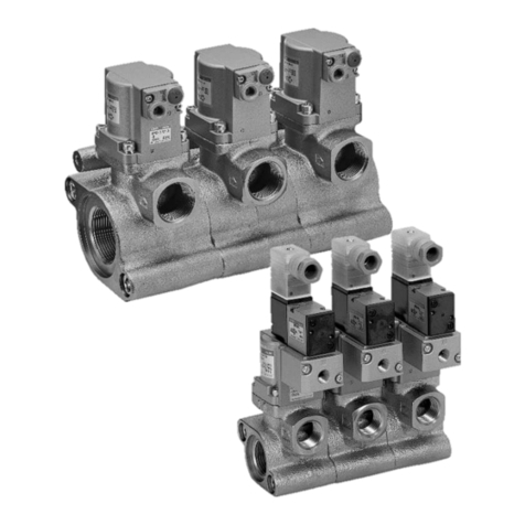
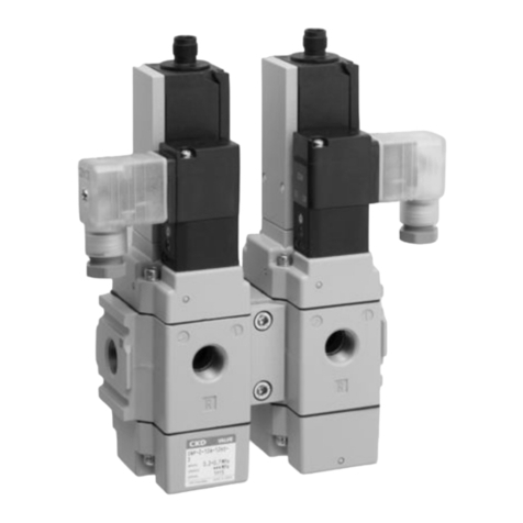
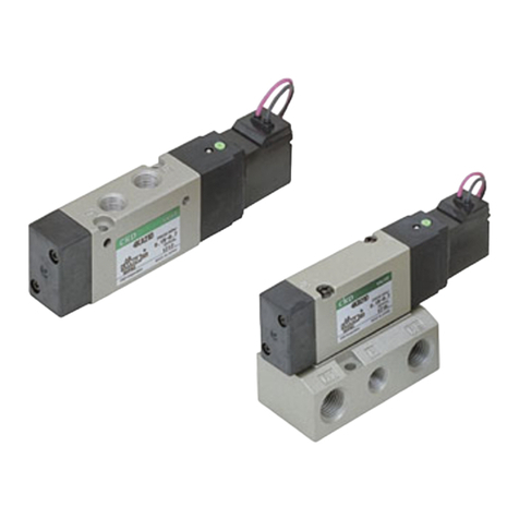
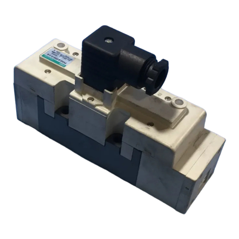
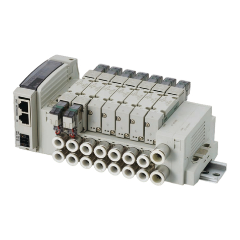
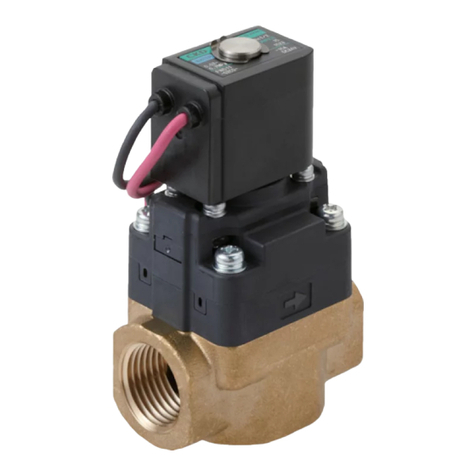
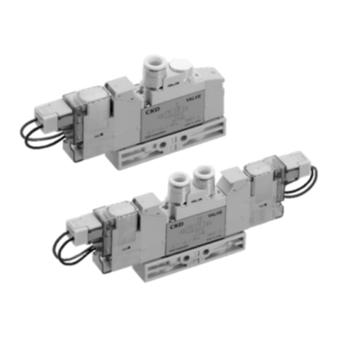
CKD M3GA/B R Series User manual

INSTRUCTION MANUAL
INSTRUCTION MANUAL
3, 5-PORT PNEUMATIC SOLENOID VALVE
(M)3GA/B R SERIES
(M)4GA/B R SERIES
(M)3GD/E R SERIES
(M)4GD/E R SERIES
・Single Valve
・Manifold (Metal Base)
SM-P00077-A/3
SM-358642
•Read this Instruction Manual before using the product.
•Read the safety notes carefully.
•Keep this Instruction Manual in a safe and convenient place for future reference.

SM-P00077-A/3 PREFACE
i 2020-04-15
PREFACE
Thank you for purchasing CKD's 3, 5-port pneumatic solenoid valve.
This Instruction Manual contains basic matters such as installation and usage instructions in order to
ensure optimal performance of the product. Please read this Instruction Manual thoroughly and use the
product properly.
Keep this Instruction Manual in a safe place and be careful not to lose it.
Product specifications and appearances presented in this Instruction Manual are subject to change
without notice.
•The product, which uses control valves such as solenoid valves, motor valves, and air operated
valves, is intended for users who have basic knowledge about materials, fluids, piping, and
electricity. CKD shall not be responsible for accidents caused by persons who selected or used the
product without knowledge or sufficient training with respect to control valves.
•Since there are a wide variety of customer applications, it is impossible for CKD to be aware of all of
them. Depending on the application or usage, the product may not be able to exercise its full
performance or an accident may occur due to fluid, piping, or other conditions. It is the responsibility
of the customer to check the product specifications and decide how the product shall be used in
accordance with the application and usage.

SM-P00077-A/3 SAFETY INFORMATION
ii 2020-04-15
SAFETY INFORMATION
When designing and manufacturing any device incorporating the product, the manufacturer has an
obligation to ensure that the device is safe. To that end, make sure that the safety of the machine
mechanism of the device, the pneumatic or water control circuit, and the electric system that controls
such mechanism is ensured.
To ensure the safety of device design and control, observe organization standards, relevant laws and
regulations, which include the following:
ISO 4414, JIS B 8370, JFPS 2008 (the latest edition of each standard), the High Pressure Gas Safety
Act, the Industrial Safety and Health Act, other safety rules, organization standards, relevant laws and
regulations
In order to use our products safely, it is important to select, use, handle, and maintain the products
properly.
Observe the warnings and precautions described in this Instruction Manual to ensure device safety.
Although various safety measures have been adopted in the product, customer's improper handling may
lead to an accident. To avoid this:
Thoroughly read and understand this Instruction Manual
before using the product.
To explicitly indicate the severity and likelihood of a potential harm or damage, precautions are classified
into three categories: "DANGER", "WARNING", and "CAUTION".
DANGER
Indicates an imminent hazard. Improper handling will cause death or serious
injury to people.
WARNING
Indicates a potential hazard. Improper handling may cause death or serious
injury to people.
CAUTION
Indicates a potential hazard. Improper handling may cause injury to people or
damage to property.
Precautions classified as "CAUTION" may still lead to serious results depending on the situation.
All precautions are equally important and must be observed.
Other general precautions and tips on using the product are indicated by the following icon.
Indicates general precautions and tips on using the product.

SM-P00077-A/3 SAFETY INFORMATION
iii 2020-04-15
Precautions on Product Use
WARNING
The product must be handled by a qualified person who has extensive knowledge and
experience.
The product is designed and manufactured as a device or part for general industrial machinery.
Use the product within the specifications.
The product must not be used beyond its specifications. Also, the product must not be modified
and additional work on the product must not be performed.
The product is intended for use in devices or parts for general industrial machinery. It is not
intended for use outdoors or in the conditions or environment listed below.
•In applications for nuclear power, railroad system, aviation, ship, vehicle, medical equipment,
and equipment that directly touches beverage or food.
•For special applications that require safety including amusement equipment, emergency
shut-off circuit, press machine, brake circuit, and safety measures.
•For applications where life or properties may be adversely affected and special safety measures
are required.
(Exception is made if the customer consults with CKD prior to use and understands the
specifications of the product. However, even in that case, safety measures must be taken to avoid
danger in case of a possible failure.)
Do not handle the product or remove pipes and devices until confirming safety.
•Inspect and service the machine and devices after confirming the safety of the entire system.
Also, turn off the energy source (air supply or water supply) and power to the relevant facility.
Release compressed air from the system and use extreme care to avoid water or electric
leakage.
•Since there may be hot or live parts even after operation has stopped, use extreme care when
handling the product or removing pipes and devices.
•When starting or restarting a machine or device that incorporates pneumatic components, make
sure that a safety measure (such as a pop-out prevention mechanism) is in place and system
safety is secured.

SM-P00077-A/3 CONTENTS
iv 2020-04-15
CONTENTS
PREFACE........................................................................................................................... i
SAFETY INFORMATION .................................................................................................. ii
Precautions on Product Use..........................................................................................iii
CONTENTS...................................................................................................................... iv
1. PRODUCT OVERVIEW............................................................................................. 1
1.1 Part Name........................................................................................................... 1
1.2 Model Number Indication....................................................................................5
1.2.1 Single valve .................................................................................................... 5
1.2.2 Manifold ..........................................................................................................8
1.2.3 Related products ..........................................................................................13
1.2.4 Kit parts ........................................................................................................14
1.3 Specifications.................................................................................................... 20
1.3.1 Common specifications ................................................................................20
1.3.2 Electrical specifications ................................................................................20
1.3.3 Response times............................................................................................ 21
1.3.4 Flow characteristics......................................................................................21
1.3.5 Weight...........................................................................................................23
1.4 Internal Structure ..............................................................................................25
1.4.1 Description of operation ...............................................................................25
2. INSTALLATION ....................................................................................................... 28
2.1 Environment......................................................................................................28
2.2 Unpacking .........................................................................................................29
2.3 Mounting ...........................................................................................................29
2.3.1 How to mount a body piping type single valve............................................. 30
2.3.2 How to mount a base piping type single valve............................................. 33
2.3.3 How to mount a manifold..............................................................................34
2.4 Piping ................................................................................................................36
2.4.1 Recommended tightening torque.................................................................36
2.4.2 Seal material.................................................................................................37
2.4.3 Flushing ........................................................................................................37
2.4.4 M5 fitting .......................................................................................................37
2.4.5 Blow circuit ...................................................................................................37
2.4.6 Exhaust port .................................................................................................37
2.4.7 Piping connection .........................................................................................37
2.4.8 Piping ports for external pilot (option symbol: K) ......................................... 39
2.5 Wiring................................................................................................................40
2.5.1 E-type connector ..........................................................................................41
2.5.2 A-type connector ..........................................................................................41
2.5.3 EJ-type ("socket with cover" type) connector...............................................42
2.5.4 DIN terminal box...........................................................................................42
2.5.5 Common terminal block (T10/T11)............................................................... 44
2.5.6 D-sub connector (T30) .................................................................................47
2.5.7 Flat cable connector (T50) ........................................................................... 51
2.5.8 Flat cable connector (T51/T52/T53)............................................................. 54
3. USAGE..................................................................................................................... 60
3.1 Safety Instructions ............................................................................................ 60
3.1.1 Air quality...................................................................................................... 60
3.1.2 Electric circuit ...............................................................................................62
3.1.3 Surgeless (option symbol: S) ....................................................................... 63
3.1.4 Low heat generating/energy saving circuit (option symbol: E) .................... 63
3.1.5 AC voltage models ....................................................................................... 63


SM-P00077-A/3 CONTENTS
v 2020-04-15
3.1.6 Pressure sensor (option symbol: G1, G2).................................................... 64
3.2 Manual Operation .............................................................................................67
3.2.1 Non-locking/locking combination manual override ......................................67
3.2.2 Residual pressure exahust mechanism (option symbol: X, X1) .................. 68
4. MAINTENANCE AND INSPECTION....................................................................... 69
4.1 Periodic Inspection............................................................................................69
4.2 Disassembling and Assembling........................................................................ 70
4.2.1 Replacement of solenoid valve ....................................................................70
4.2.2 How to replace a coil assembly.................................................................... 70
4.2.3 How to replace a cartridge type fitting (4GA/B R, 4GD/E R) .......................71
4.2.4 How to change piping connection specifications (4GA/B R) .......................73
4.3 Adding a Valve to the Reduced Wiring Manifold .............................................. 74
4.3.1 How to add to the position where spare wiring is equipped ........................74
4.3.2 How to add to the position where no spare wiring is equipped ...................74
4.3.3 How to open and close the reduced wiring cover ........................................75
4.3.4 Instructions for wiring the electric circuit board connectors......................... 76
5. TROUBLESHOOTING............................................................................................. 79
5.1 Problems, Causes, and Solutions ....................................................................79
6. REFERENCE INFORMATION................................................................................. 80
6.1 Port Identification ..............................................................................................80
7. WARRANTY PROVISIONS..................................................................................... 81
7.1 Warranty Conditions .........................................................................................81
7.2 Warranty Period ................................................................................................81

SM-P00077-A/3 1. PRODUCT OVERVIEW
1 2020-04-15
1. PRODUCT OVERVIEW
1.1 Part Name
Mounting plate
Individual wiring manifold
Reduced wiring manifold
(figure shown is DIN rail mount)
Common terminal block (T10)
M3 thread fastening type
Common terminal block (T11)
Clamping type
D-sub connector (T30)
Body piping type single valve
Base piping type single valve

SM-P00077-A/3 1. PRODUCT OVERVIEW
2 2020-04-15
Serial transmission (T6)
Serial transmission (T8)
DIN terminal box (B)
Socket with cover (EJ)
Flat cable connector (T50)
Flat cable connector (T51)
Pressure sensor (G1)
Pressure sensor (G2)
Residual pressure exhaust
mechanism (X, X1)

SM-P00077-A/3 1. PRODUCT OVERVIEW
3 2020-04-15
No.
Part name
Description
1
Lead wire
Wire which has no polarity.
2
Electrical component cover
Cover provided with a power indicator on the top surface which lights green while the
coil is energized (only for E-type and A-type connectors).
3
Coil assembly
Coil assembly which varies depending on the type of electrical connection and voltage
selected for the valve. Not interchangeable with No. 36.
4
Manual protection cover
Cover which prevents accidental operation of the manual override and is opened to
operate the manual override.
5
Manual override
Manual operation device which has both locking and non-locking overrides.
6
Single valve
Valve equipped with a mechanism which opens/closes an air passage.
7
Single valve mounting screw
Screw used for securing a single valve to various bases (2 screws provided for each
valve).
8
Subplate
Subplate which comes assembled to a base piping type single valve.
9
Piping port
Port provided for supply, indicated by 1(P); for exhaust, indicated by 3(R2) or 5(R1); for
output, indicated by 2(B) or 4(A).
10
Fitting
Cartridge type push-in fitting which can be replaced.
11-1
Fitting stopper pin
Pin used for securing a cartridge type fitting.
(4GA R Series)
11-2
Fitting stopper plate
Plate used for securing a cartridge type fitting. Not interchangeable with No. 17.
(4GD R Series)
12
Pipe adaptor
Adaptor which comes assembled to a body piping type single valve.
13
Mounting hole
Hole used for direct mounting.
14
Mounting plate
Plate used for vertical mounting of a body piping type single valve.
15
Manifold base
Metal base manifold provided with multiple piping ports.
16
Masking plate
Plate replaced by a single valve when adding a valve.
17
Fitting stopper plate
Plate used for securing a cartridge type fitting.
Not interchangeable with No. 11-2.
18
Electrical component block
Component block which stores and secures a printed circuit board mounted with PCB
connectors.
19
Wiring duct
Duct provided for protecting cables contained.
20
DIN rail
Rail which complies with DIN standard (German Industry Standard) and is used for
mounting a solenoid valve.
21
DIN rail mounting screw
Screw used for securing the entire manifold in place on the DIN rail and located at both
ends of the base.
22
Holder
Holder used together with the DIN rail mounting screw (only for 4G2/4G3).
23
Spare cable
Cable used when adding a valve.
24
Terminal block
Connector block provided with a set of terminals for controlling the manifold valves.
25
Cover
Cover which is opened to work on wiring and must be closed before energization in
order to avoid an electric shock.
26
Terminal block layout
Diagram which indicates the layout of the terminal block and on which notes can be
written.
27
D-sub 25-pin connector
Connector provided with a set of terminals for controlling the manifold valves.
28
Mounting screw
Screw used for securing the connectors (screw size is M2.6).
29
Connector rotation button
Button used for changing the direction of the connector wiring upward or sideways.
Pressing in the button releases the lock and allows the connector to rotate.
Rotating the connector to a predetermined position pushes out the button and locks the
connector.
30
Power supply terminal block
Terminal block used when an external power supply is required.
31
Power polarity marking
Marking which indicates the power polarity (▽ mark indicates the ground side).
32
Power indicator
Indicator which lights up when power is supplied with right polarity.

SM-P00077-A/3 1. PRODUCT OVERVIEW
4 2020-04-15
No.
Part name
Description
33
Flat cable connector
Connector provided with a set of terminals for controlling the manifold valves.
34
Serial transmission slave unit
Slave unit specifically designed for manifold manufactured by CKD.
35
DIN terminal box
Terminal box provided with a power indicator which lights green while the coil is
energized.
36
Coil assembly
Coil assembly provided for DIN terminal box type valve. Not interchangeable with No. 3.
37
Socket with cover
Socket provided with a covered cabtyre cable (only for E-type connectors).
38
Pressure sensor
Sensor used for detecting pressure of port 4(A).
39
Pressure sensor
Sensor used for detecting pressure of port 2(B)/4(A).
40
Residual pressure exhaust
mechanism
Mechanism in 3-position all ports closed and 3-position ABR connection models and
used for releasing pressure of outlet port to the atmosphere.

SM-P00077-A/3 1. PRODUCT OVERVIEW
5 2020-04-15
1.2 Model Number Indication
1.2.1 Single valve
(a) Number of ports
(b) Piping direction
(c) Series
(d) Solenoid position
(e) Port size
Symbol
Description
Symbol
Description
Symbol
Description
Symbol
Description
Note 1
3
3-port valve (two
units integrated)
A
Top
(body piping)
1
M4G1R
1
2-position
Single
4
5-port valve
B
Side
(base piping)
2
M4G2R
2
2-position
Double
D
Top
(body piping)
3
M4G3R
3
3-position
All ports closed
E
Side
(base piping)
4
3-position
ABR connection
5
3-position
PAB connection
1
NC: Normally closed
(3GA, 3GD)
11
NO: Normally open
(3GA, 3GD)
66
Two 3-port valves
integrated type
(NC - NC)
67
Two 3-port valves
integrated type
(NC - NO)
76
Two 3-port valves
integrated type
(NO - NC)
77
Two 3-port valves
integrated type
(NO - NO)
(f) Electrical
connection
(g) Option
(h) Rated voltage
Note 2
Note 3
Symbol
Description
1
100 VAC
2
200 VAC
3
24 VDC
4
12 VDC
For precautions on selecting the model number, refer to the catalog.
●
Single valve
●
Single valve for mounting on base
G
9
R
G
0
R
2
E2
C6
3
1
2
E2
C6
A
A
4
4
1
H
3
(
b
)
(
f
)
(
g
)
(
h
)
(
a
)
(
e
)
(
c
)
(
d
)
H
(
b
)
(
f
)
(
g
)
(
h
)
(
a
)
(
e
)
(
c
)
(
d
)

SM-P00077-A/3 1. PRODUCT OVERVIEW
6 2020-04-15
Note 1: (e) Port size
Symbol
Description
Variation
Ports 4(A), 2(B)
Ports P, R1, R2
CF
ø1.8 barbed fitting
M5
C18
ø1.8 push-in fitting
M5
C4
ø4 push-in fitting
M5, Rc1/8
C6
ø6 push-in fitting
M5, Rc1/8, Rc1/4
C8
ø8 push-in fitting
Rc1/8, Rc1/4
C10
ø10 push-in fitting
Rc1/4
M5
M5
M5
06
Rc1/8
Rc1/8
08
Rc1/4
Rc1/4
C3N
ø1/8 push-in fitting
M5
C4N
ø5/32 push-in fitting
M5
C6N
ø1/4 push-in fitting
1/8NPT
C8N
ø5/16 push-in fitting
1/8NPT, 1/4NPT
C10N
ø3/8 push-in fitting
1/4NPT
06N
1/8NPT
1/8NPT
08N
1/4NPT
1/4NPT
10N
3/8NPT
3/8NPT
C4G
ø4 push-in fitting
G1/8
C6G
ø6 push-in fitting
G1/8
C8G
ø8 push-in fitting
G1/8
06G
G1/8
G1/8
08G
G1/4
G1/4
00
Single valve for mounting on base
-
Note 2: (f) Electrical connection
Symbol
Description
Lead wire, DIN terminal box
Blank
Grommet lead wire (300 mm)
B
DIN terminal box (Pg7)
With surge suppressor/lamp
BN
DIN terminal box (Pg7) (without terminal box)
With surge suppressor
E-type connector (top and side socket entries)
E0
Lead wire (300 mm)
E00
Lead wire (500 mm)
E01
Lead wire (1000 mm)
E02
Lead wire (2000 mm)
E03
Lead wire (3000 mm)
E0N
Without lead wire (without socket)
E1
Without lead wire (with socket/terminal)
E2
Lead wire (300 mm)
With surge suppressor/lamp
E20
Lead wire (500 mm)
With surge suppressor/lamp
E21
Lead wire (1000 mm)
With surge suppressor/lamp
E22
Lead wire (2000 mm)
With surge suppressor/lamp
E23
Lead wire (3000 mm)
With surge suppressor/lamp
E2N
Without lead wire (without socket)
With surge suppressor/lamp
E3
Without lead wire (with socket/terminal)
With surge suppressor/lamp
EJ-type connector (socket with cover, top and side socket entries)
E01J
Lead wire (1000 mm)
E02J
Lead wire (2000 mm)
E03J
Lead wire (3000 mm)
E21J
Lead wire (1000 mm)
With surge suppressor/lamp
E22J
Lead wire (2000 mm)
With surge suppressor/lamp
E23J
Lead wire (3000 mm)
With surge suppressor/lamp
For precautions on selecting the model number, refer to the catalog.

SM-P00077-A/3 1. PRODUCT OVERVIEW
7 2020-04-15
Note 3: (g) Option
Symbol
Description
Blank
Non-locking/locking combination manual override
M
Non-locking type manual override
H
Equipped with exhaust malfunction prevention valves
P
Mounting plate
K
External pilot
A
Ozone/cutting oil proof
S
Surgeless
E
Low heat generating/energy saving circuit
F
Built-in A/B-port filter
G1
1-port detection type pressure sensor (pressure range: 0 MPa to 0.7 MPa)
G2
2-port detection type pressure sensor (pressure range: 0 MPa to 0.7 MPa)
X
Non-locking type residual pressure exhaust mechanism
X1
Locking type residual pressure exhaust mechanism
For precautions on selecting the model number, refer to the catalog.

SM-P00077-A/3 1. PRODUCT OVERVIEW
8 2020-04-15
1.2.2 Manifold
(a) Number of ports
(b) Piping direction
(c) Series
(d) Solenoid position
(e) Port size
Symbol
Description
Symbol
Description
Symbol
Description
Symbol
Description
Note 4
3
3-port valve (two
units integrated)
A
Top
(body piping)
1
M4G1R
1
2-position
Single
4
5-port valve
B
Side
(base piping)
2
M4G2R
2
2-position
Double
D
Top
(body piping)
3
M4G3R
3
3-position
All ports closed
E
Side
(base piping)
4
3-position
ABR connection
5
3-position
PAB connection
1
NC: Normally closed
(3GA, 3GD)
11
NO: Normally open
(3GA, 3GD)
66
Two 3-port valves
integrated type
(NC - NC)
67
Two 3-port valves
integrated type
(NC - NO)
76
Two 3-port valves
integrated type
(NO - NC)
77
Two 3-port valves
integrated type
(NO - NO)
8
Mixed
(f)
Electrical
connection
(g)
Terminal/connector pin
layout
(h)
Option
(i)
Mount type
(j)
Number of stations
(k)
Rated voltage
Note 5
Symbol
Description
Note 6
Symbol
Description
Symbol
Description
Symbol
Description
Blank
Standard wiring for
individual
reduced wiring
Blank
Direct mount
2 to 20
n stations
1
100 VAC
D
DIN rail mount
2
200 VAC
3
24 VDC
W
Double wiring for
reduced wiring
4
12 VDC
W1
Double wiring for
reduced wiring
(with single spare
wiring)
For precautions on selecting the model number, refer to the catalog.
●Manifold model no.
●Single valve for mounting on base

SM-P00077-A/3 1. PRODUCT OVERVIEW
9 2020-04-15
Note 4: (e) Port size
Symbol
Description
Variation
Ports 4(A), 2(B)
Ports P, R1, R2
CF
ø1.8 barbed fitting
Rc1/8
C18
ø1.8 push-in fitting
Rc1/8
C4
ø4 push-in fitting
Rc1/8, Rc1/4
C6
ø6 push-in fitting
Rc1/8, Rc1/4, Rc3/8
C8
ø8 push-in fitting
Rc1/8, Rc1/4, Rc3/8
C10
ø10 push-in fitting
Rc1/4, Rc3/8
CL18
ø1.8 L-shape push-in fitting (upward)
Rc1/8
CL4
ø4 L-shape push-in fitting (upward)
Rc1/8
CL6
ø6 L-shape push-in fitting (upward)
Rc1/8, Rc1/4
CL8
ø8 L-shape push-in fitting (upward)
Rc1/4, Rc3/8
CL10
ø10 L-shape push-in fitting (upward)
Rc3/8
CD18
ø1.8 L-shape push-in fitting (downward)
Rc1/8
CD4
ø4 L-shape push-in fitting (downward)
Rc1/8
CD6
ø6 L-shape push-in fitting (downward)
Rc1/8, Rc1/4
CD8
ø8 L-shape push-in fitting (downward)
Rc1/4, Rc3/8
CD10
ø10 L-shape push-in fitting (downward)
Rc3/8
CX
Mix push-in fitting
Rc1/8, Rc1/4, Rc3/8
M5
M5
Rc1/8
06
Rc1/8
Rc1/4
08
Rc1/4
Rc3/8
C3N
ø1/8 push-in fitting
1/8NPT
C4N
ø5/32 push-in fitting
1/8NPT
C6N
ø1/4 push-in fitting
1/4NPT
C8N
ø5/16 push-in fitting
1/4NPT, 3/8NPT
C10N
ø3/8 push-in fitting
3/8NPT
CL3N
ø1/8 L-shape push-in fitting (upward)
1/8NPT
CL4N
ø5/32 L-shape push-in fitting (upward)
1/8NPT
CL6N
ø1/4 L-shape push-in fitting (upward)
1/4NPT
CL8N
ø5/16 L-shape push-in fitting (upward)
1/4NPT
CXN
Mix push-in fitting
1/8NPT, 1/4NPT, 3/8NPT
M5N
M5
1/8NPT
06N
1/8NPT
1/4NPT
08N
1/4NPT
3/8NPT
C4G
ø4 push-in fitting
G1/8, G1/4
C6G
ø6 push-in fitting
G1/8, G1/4
C8G
ø8 push-in fitting
G1/4
CL4G
ø4 L-shape push-in fitting (upward)
G1/8
CL6G
ø6 L-shape push-in fitting (upward)
G1/8, G1/4
CL8G
ø8 L-shape push-in fitting (upward)
G1/4
CXG
Mix push-in fitting
G1/8, G1/4
M5G
M5
G1/8
06G
G1/8
G1/4
00
Single valve for mounting on base
-
For precautions on selecting the model number, refer to the catalog.

SM-P00077-A/3 1. PRODUCT OVERVIEW
10 2020-04-15
Note 5: (f) Electrical connection
Individual wiring
Symbol
Description
Lead wire, DIN terminal box
Blank
Grommet lead wire (300 mm)
B
DIN terminal box (Pg7)
With surge suppressor/lamp
BN
DIN terminal box (Pg7) (without terminal box)
With surge suppressor
E-type connector (top and side socket entries)
E0
Lead wire (300 mm)
E00
Lead wire (500 mm)
E01
Lead wire (1000 mm)
E02
Lead wire (2000 mm)
E03
Lead wire (3000 mm)
E0N
Without lead wire (without socket)
E1
Without lead wire (with socket/terminal)
E2
Lead wire (300 mm)
With surge suppressor/lamp
E20
Lead wire (500 mm)
With surge suppressor/lamp
E21
Lead wire (1000 mm)
With surge suppressor/lamp
E22
Lead wire (2000 mm)
With surge suppressor/lamp
E23
Lead wire (3000 mm)
With surge suppressor/lamp
E2N
Without lead wire (without socket)
With surge suppressor/lamp
E3
Without lead wire (with socket/terminal)
With surge suppressor/lamp
EJ-type connector (socket with cover, top and side socket entries)
E01J
Lead wire (1000 mm)
E02J
Lead wire (2000 mm)
E03J
Lead wire (3000 mm)
E21J
Lead wire (1000 mm)
With surge suppressor/lamp
E22J
Lead wire (2000 mm)
With surge suppressor/lamp
E23J
Lead wire (3000 mm)
With surge suppressor/lamp
For precautions on selecting the model number, refer to the catalog.

SM-P00077-A/3 1. PRODUCT OVERVIEW
11 2020-04-15
Reduced wiring
Symbol
Description
T10
Common terminal block (M3 thread)
Left side connection
T10R
Right side connection
T11
Common terminal block (clamping)
Left side connection
T11R
Right side connection
T30
D-sub connector
Left side connection
T30R
Right side connection
T50
20-pin flat cable connector
(with power supply terminal)
Left side connection
T50R
Right side connection
T51
20-pin flat cable connector
(without power supply terminal)
Left side connection
T51R
Right side connection
T52
10-pin flat cable connector
(without power supply terminal)
Left side connection
T52R
Right side connection
T53
26-pin flat cable connector
(without power supply terminal)
Left side connection
T53R
Right side connection
T6A0
UNI-WIRE SYSTEM
NPN 8 points
T6A1
NPN 16 points
T6C0
CompoBus/S
NPN 8 points
T6C1
NPN 16 points
T6E0
S-Link
NPN 8 points
T6E1
NPN 16 points
T6G1
CC-Link
NPN 16 points
T6J0
UNI-WIRE H SYSTEM
NPN 8 points
T6J1
NPN 16 points
T8D1
DeviceNet
(thin type)
NPN 16 points
T8D2
NPN 32 points
T8DP1
PNP 16 points
T8DP2
PNP 32 points
T8G1
CC-Link
(thin type)
NPN 16 points
T8G2
NPN 32 points
T8GP1
PNP 16 points
T8GP2
PNP 32 points
T8P1
PROFIBUS-DP
(thin type)
NPN 16 points
T8P2
NPN 32 points
T8PP1
PNP 16 points
T8PP2
PNP 32 points
T8EC1
EtherCAT
(thin type)
NPN 16 points
T8EC2
NPN 32 points
T8ECP1
PNP 16 points
T8ECP2
PNP 32 points
T8EN1
EtherNet/IP
(thin type)
NPN 16 points
T8EN2
NPN 32 points
T8ENP1
PNP 16 points
T8ENP2
PNP 32 points
A2N
Without lead wire (without socket)
With surge suppressor/lamp
For precautions on selecting the model number, refer to the catalog.

SM-P00077-A/3 1. PRODUCT OVERVIEW
12 2020-04-15
Note 6: (h) Option
Symbol
Description
Blank
Non-locking/locking combination manual override
M
Non-locking type manual override
H
Equipped with exhaust malfunction prevention valves
K
External pilot
A
Ozone/cutting oil proof
S
Surgeless
E
Low heat generating/energy saving circuit
F
Built-in A/B-port filter
G1
1-port detection type pressure sensor (pressure range: 0 MPa to 0.7 MPa)
G2
2-port detection type pressure sensor (pressure range: 0 MPa to 0.7 MPa)
X
Non-locking type residual pressure exhaust mechanism
X1
Locking type residual pressure exhaust mechanism
Z1
Air supply spacer
Z2
In-stop valve spacer
Z3
Exhaust spacer
Z6
Spacer-type pilot check valve
For precautions on selecting the model number, refer to the catalog.

SM-P00077-A/3 1. PRODUCT OVERVIEW
13 2020-04-15
1.2.3 Related products
◼Mounting rail
<N4GR-BAA>
•Minimum length is 87.5 mm.
•Select the length in pitches of 12.5 mm.
◼Silencer
<SLM-M5> <SLW-6S, 8S>
Model
Port size
A
B
C
D
E
SLW-6S
R1/8
22
13.3
10.5
6
10.5
SLW-8S
R1/4
28
19
14.8
9
15.4
<SLW-6A, 8A, 10A, 10L>
Model
Noise
reduction
effect
dB(A)
Effective
cross-
sectional
area mm2
A
B
C
D
E
Port
size
SLW-6A
30 or
more
10
34.5
28
16.5
10
7
R1/8
SLW-8A
30 or
more
20
44.5
36
20
13
8.5
R1/4
SLW-10A
30 or
more
30
58.5
48.5
25.5
17
12
R3/8
SLW-10L
30 or
more
60
68.2
58.4
28
19
12
R3/8
◼Blanking plug
Model
D
L
ℓ
d
PG-P2-B
ø1.8
20
13
5
GWP4-B
ø4
27
16
6
GWP6-B
ø6
29
11.5
8
GWP8-B
ø8
33
14
10
GWP10-B
ø10
40
18.5
12
◼Screw plug
<4G1R-M5P><4G□R-□P>
Model
Applicable port size
4G1R-M5P
M5
4G2R-06P
Rc1/8
4G3R-08P
Rc1/4
4G3R-10P
Rc3/8
4G2R-06NP
NPT1/8
4G3R-08NP
NPT1/4
4G3R-10NP
NPT3/8
4G2R-06GP
NPT1/8
4G3R-08GP
NPT1/4
4G3R-10GP
NPT3/8
Port size
Cross section A-A
Port size
Note 1: Check the dimensions to select the right silencer.
Note 2: Use SLW-8S for DIN rail mount type M4GA2 R.
Interference will occur if SLW-8A is used.
For precautions on selecting the model
number, refer to the catalog.

SM-P00077-A/3 1. PRODUCT OVERVIEW
14 2020-04-15
1.2.4 Kit parts
◼Coil assembly
Part name
Model number
Coil assembly
(for individual wiring)
4GR-Electrical connection-Option-COIL-Rated voltage
1: 100 VAC
2: 200 VAC
3: 24 VDC
4: 12 VDC
Blank: Standard
A: Ozone-proof
Blank: Grommet lead wire
E□: E-type connector
E□J: EJ-type connector
B: DIN terminal box
Coil assembly
(for reduced wiring)
4GR-A2N-Option-COIL-Rated voltage
3: 24 VDC
4: 12 VDC
Blank: Standard
A: Ozone-proof
◼Lead wire related parts
Part name
Model number
E-type connector socket assembly
4GR-SOCKET-ASSY-Electrical connection-Rated voltage
1: 100 VAC
3: 24 VDC
4: 12 VDC
E□: E-type connector
Socket assembly with cover
4GR-SOCKET-ASSY-Electrical connection
E□J: EJ-type connector
DIN terminal box
4G-TERMINAL-BOX-Rated voltage
1: 100 VAC
2: 200 VAC
3: 24 VDC
4: 12 VDC
For precautions on selecting the model number, refer to the catalog.
This manual suits for next models
3
Table of contents
Other CKD Control Unit manuals

CKD
CKD M4GA4-T6G1 User manual

CKD
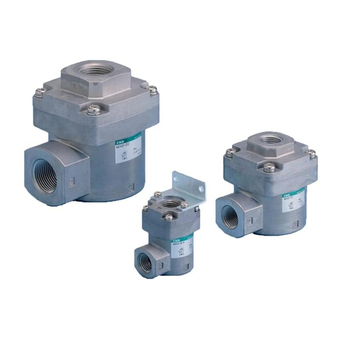
CKD 4KA3 User manual

CKD
CKD NP13 Series User manual

CKD
CKD QEL Series User manual

CKD
CKD QEV2 User manual

CKD
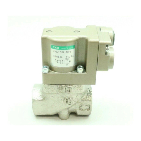
CKD CVE2 Series Installation and operating manual

CKD
CKD 3GD/E1 Series User manual

CKD
CKD MN3GD/E1 Series User manual

CKD
CKD PV5G Series User manual

CKD
CKD SNP Series User manual
Popular Control Unit manuals by other brands

Sonder
Sonder TELKAN 1 GSM 3G Manual of installation and use

NXP Semiconductors
NXP Semiconductors A3M34SL039 manual

U-Prox
U-Prox Button user manual

DMP Electronics
DMP Electronics 734N Series Installation and programming guide

Maxim Integrated
Maxim Integrated MAXIM001 MGT quick start guide

Warren rupp
Warren rupp SANDPIPER G Series Original instructions