EUTHANEX SMARTBOX PRODIGY EA-3300TS User manual

AutoCO2System
PRODIGYEA‐3300TS
877‐559‐0159TollFreeE‐ZSystems/EuthanexCorp.
610‐882‐3800PhoneP.O.Box3544
610‐882‐3801FaxPalmer,PA18043
www.euthanex.com[email protected]

2
TABLE OF CONTENTS
Disclaimer____________________________________ 3
SystemOverview_______________________________ 4
Safety________________________________________ 5
SystemSetup__________________________________ 6
OperatingtheSystem___________________________9
AdministratorInstructions_______________________13
Troubleshooting_______________________________23
EMC / EMI.
This equipment has been tested and found to
comply with the limits for a Class A Equipment,
pursuant to part 15 of the FCC rules.
IEC 61326-1:2005 / EZ 61326-1:2006

3
DISCLAIMER:
THISMANUALMUSTBEREADBEFORESETTINGUPANDOPERATINGTHESMARTBOXAUTOCO2
SYSTEM.Theusershouldbethoroughlyfamiliarwiththecontentsofthismanualpriortousingthe
systemwithanimals.Onlytechniciansthatareproperlytrainedshouldoperatethesystem.
Theuser/ownerofthisequipmentshallhavethesoleresponsibilityforanydamageorinjuryresulting
fromoperationthatisnotinaccordancewiththeauthorizedinstructions.
Thisincludes,butisnotlimitedto,operatingtheequipmentoutsideofrecommendedsafetylevels,
variationfromspecifiedoperatinginstructions,andnotfollowingstandardlaboratorysafetyprocedures
whenworkingwithanestheticagentsandvolatilecompressedgases.
ThesystemanditscomponentsmustonlybemodifiedorrepairedbyEuthanex®authorizedservice
technicians.Impropermodificationorrepairmayresultindangertopersonnel,harmordeathto
animal,and/orequipmentdamage.Theuser/ownerofthisequipmentshallhavethesoleresponsibility
foranydamageorinjuryresultingfromimpropermaintenanceandrepairthatisnotdonebyauthorized
maintenanceandrepairpersonnel.
Partsthathavefailed,inwholeorinpart,exhibitexcessivewear,arecontaminatedorareotherwiseat
theendoftheirusefullife,shouldnotbeusedandshouldbereplacedwithpartssuppliedbyEuthanex
Corporation.Tamperingwiththemaincontrolunitbyunauthorizedpersonnelautomaticallyvoidsall
warrantiesandspecifications.Themanufacturerassumesnoresponsibilityforanymalfunctionorfailure
oftheunitiftamperingissuspected.

4
OVERVIEW:
TheSMARTBOX®Prodigyallowsadministratorstoprogramanunlimitednumberofcagesandsizes.The
administratoronlyneedstoselecttheflowratepercentage.TheEA‐33000TSwillautomaticallycalculate
therequiredflowrate.Anunlimitednumberofpassword‐protectedusersaddsevenmoreflexibility.
Eachusercanonlyseethecagesauthorizedbytheadministrator.Theusercanconnectupto3cagesat
onetime.TheTouchScreendisplayshowsthecycle,cycletime,andtotaltimeremaining.
Pleaserefertothe“FlowRate&PresetTimes”sectiontoderivetheAVMArecommendedflowrate.
POWER
SWITCH
DC
POWER
GASIN
GASOUTLETS
TOCAGES

T
h
s
y
i
n
u
n
pr
m
pe
1.
2.
3.
4.
5.
6.
7.
8.
9.
1
0
1
1
1
2
h
e lightning fla
s
y
mbol within an
n
tended to alert t
h
n
insulated "dan
g
r
oduct's enclosu
r
m
agnitude to con
s
e
rsons.
Read these i
n
Keep these i
n
Heed all wa
r
Follow all i
n
Do not use t
h
Do not clea
n
unit.
Do not bloc
k
Install in ac
c
instructions.
Do not insta
l
as radiators,
unit that pro
d
Do not defe
a
p
olarized or
p
olarized pl
u
wider than t
h
has two bla
d
p
rong. The
w
are provided
p
lug does n
o
electrician f
o
outlet.
0
.Protect the p
on or pinche
d
convenience
where they
e
1
.Unplug this
u
storms or w
h
time.
2
.Refer all ser
v
p
ersonnel. S
e
unit has bee
n
such as pow
e
damaged, li
q
have fallen i
n
unit has bee
n
moisture, do
e
b
een droppe
d
s
h with an arrow
equilateral tria
n
h
e user to the p
r
g
erous voltage"
w
r
e that may be o
f
s
titute a risk of
e
n
structions.
n
structions.
r
nings.
n
structions.
h
is unit near wa
t
n
by spraying liq
u
k
any ventilatio
n
c
ordance with th
e
l
l near any heat
s
heat registers, s
t
d
uce heat.
a
t the safety pur
p
grounding-type
u
g has two blad
e
h
e other. A grou
n
d
es and a third g
r
w
ide blade or th
e
for your safety.
o
t fit into your o
u
o
r replacement
o
ower cord from
d
particularly at
receptacles, an
d
e
xit from the uni
t
u
nit during ligh
t
h
en unused for l
o
v
icing to qualifi
e
e
rvicing is requ
i
n
damaged in an
y
er
-supply cord o
q
uid has been sp
i
n
to the unit, the
n
exposed to rai
n
e
s not operate n
o
d
.
hea
d
n
gle, is
r
esence of
w
ithin the
f
sufficient
e
lectric shock to
t
er.
u
id directly ont
o
n
openings.
e
manufacturer'
s
s
ources such
t
oves, or othe
r
p
ose of the
plug. A
e
s with one
n
ding type plug
r
ounding
e
third prong
If the provide
d
u
tlet, consult an
o
f the obsolete
being walke
d
plugs,
d
the point
t
.
t
ning
o
ng periods of
e
d service
i
red when the
y
way,
r plug is
i
lled or objects
n
o
r
o
rmally, or has
5
o
s
The
e
inten
d
oper
a
the li
t
War
n
Caut
Serv
i
Volt
a
Press
u
Tem
p
e
xclamation poi
n
d
ed to alert the
u
a
ting and mainte
n
t
erature accomp
a
n
ing!
To reduce
t
do not exp
o
moisture.
Use line co
Be advised
require the
cord and at
t
shipped wi
t
installation
contact us
f
This equip
m
socket outl
e
should be
e
Do not inst
Do not ope
n
inside.
ion: You are ca
u
modificati
o
manual co
u
this equip
m
i
ce
There are
n
All service
personnel.
a
ge 100-
2
selec
t
u
re 175
p
p
0to
con
d
n
t within an equ
i
u
ser to the prese
n
n
ance (servicin
g
a
nying the prod
u
t
he risk of fire o
r
o
se this unit to r
a
rd supplied wit
h
that different o
p
use of different
t
achment plugs.
t
h the requested
requirements c
h
f
or the correct p
l
m
ent should be
i
e
t and disconne
c
e
asily accessible
.
all in a confine
d
n
the unit - risk
u
tioned that any
o
ns not expressl
y
u
ld void your au
t
m
ent.
n
o use
r
-servicea
b
must be perfor
m
2
40 v ac 50-60h
z
t
)
p
si max to inlet
40
°
C<>10to
8
d
ensation)
i
lateral triangle
i
n
ce of importan
t
g
) instructions i
n
u
ct.
r
electric shock,
a
in o
r
h
the product.
p
erating voltage
s
types of line
The unit was
plug. If the
h
ange please
l
ug.
i
nstalled near th
e
c
tion of the devi
c
.
d
space.
of electric shoc
k
change o
r
y
approved in th
i
t
hority to operat
b
le parts inside.
m
ed by qualifie
d
z
5 amp Max (a
u
8
5%RH(no
i
s
t
n
s
e
c
e
k
i
s
e
d
u
to

SYS
T
Theunit
c
1.Theu
n
mounted
2.Conne
theProdi
g
3.Conne
c
valveon
t
WARNIN
G
closedan
thesafet
y
T
EM SE
T
c
omeprepro
g
n
itsitsonthe
tothewall
w
cttheextern
g
ylocatedo
n
c
tthesupplie
t
heEuthanex
GAS
W
G
‐Aminimu
m
dwillnotop
e
y
popoffvalv
T
U
P
:
g
ramwithba
s
tabletopor
c
w
iththeoptio
alCO
2
gaslin
n
theleftside
dcagehose
f
Lid.Theuni
t
W
ILLNOTFLO
m
ofonecag
e
e
nuntilconn
e
etoeruptor
s
esetting.A
d
c
anattachto
nalwallmou
efromtheP
S
.Checkthe
F
f
romtheout
p
t
willsuppor
t
WINTOLIDI
e
mustbeco
n
e
cted.Failur
internalhos
e
6
d
ditionalcha
ametalsurf
a
ntingbracke
t
S
Iregulator
o
F
lowRateGu
i
p
utofthePr
o
t
operationo
f
FTHECOUP
L
n
nected.All
q
etodosowi
e
stodisconn
ngescanbe
m
a
cewiththe
m
t
.
o
rin‐linePSI
r
i
detodeter
m
o
digy(locate
d
f
3cagesina
L
ERISNOTP
R
q
uickdiscon
n
llcauseover
ect.
m
ake.Ref.t
o
m
agneticfee
t
r
egulator,to
t
m
inethecorr
e
d
ontherigh
t
cycle.
R
OPERLYATT
A
n
ectfittings
a
pressurizati
o
o
Page12
t
,Itcanalso
b
t
hegasinput
e
ctPSIsettin
g
t
side)tothe
A
CHED.
a
renormally
o
nandmyre
s
b
e
of
g
s.
input
s
ultin

7
4.PlacetheEuthanexLidonthecage.Toproperlymaketheconnection,pullbackthecouplerandslide
itoverthemalestem.Thecouplerwillsnapbackintoplaceandsecuretheconnection.Thesystemis
readyforoperation.
Setfor20PSIout.
5.AttachtheheatedregulatortotheCO2tank.ItisrecommendedthatTeflontapebeusedontheCO2
tankthreadsbeforeattachingregulator.Useawrenchtotightenthemountedregulator.Setfor20
PSIout.
Werecommendsettingtheincomingpressureto20PSIbutdonotexceed35PSI.Theunitwill
workonlowincomingpressurebutmayresultintheinabilitytoachievehigheroutputflow
rates.
Note:TheEA‐550ElectricallyHeatedRegulatorisrecommendedtooperatethesystem.Usinganon‐
heatedregulatorwilllikelyresultinfrozenCO2lines.
Setupisnowcomplete.
Theimag e cann ot be disp layed. Yo ur comp uter may not hav e enou gh memory too pen the image, o r the image may h ave been co rrup ted. Restart yo ur comp uter, and then op en the file again . If the r ed x still app ears, y ou may hav e to d eleteth e image and then insert it again.
MountedHeatedRegulator

OPE
R
1)Press
foru
s
runni
2)Ensu
r
3)Open
gaug
e
4)Open
flow
o
Setther
e
WARNIN
G
closedan
thesafet
y
Werec
o
The
achi
e
PSIG
a
Gas
V
R
ATING
theOnswit
c
s
e.Ifthisist
h
nganycycle
s
r
ethelid(s)h
a
thegasflow
e
shouldber
e
thegasflow
o
fgastothe
c
e
gulatorto2
G
‐Aminimu
m
dwillnotop
e
y
popoffvalv
o
mmend
s
unitwill
w
e
vehighe
r
a
uge
V
alve
THE S
Y
c
hinthebac
k
h
efirsttime
u
s
(seeadmini
s
a
sbeenplac
e
fromtheCO
2
e
ading800‐
8
outofther
e
c
ontroller.
0PSI.
m
ofonecag
e
e
nuntilconn
e
etoeruptor
s
ettingthe
w
orkonlo
w
r
outputfl
o
Y
STE
M
:
k
oftheunit.
u
singthesys
t
s
tratorinstru
c
e
donthecag
2
tankbytur
n
8
50PSIifthe
t
e
gulatorbyt
u
e
mustbeco
n
e
cted.Failur
internalhos
e
incoming
w
incomin
g
o
wrates.
8
Theunitwill
t
emtheoper
a
c
tionspg13)
e(s)andhos
e
n
ingthetank
t
ankisfull,l
e
u
rningtheco
n
n
nected.All
q
etodosowi
e
stodisconn
pressure
t
g
pressure
bootandco
m
a
tingparam
e
.
e
sarecorrec
t
valveknobc
o
e
ssifitisnot
a
n
trolbarcou
n
q
uickdiscon
n
llcauseover
ect.
t
o20PSIb
butmayr
e
C
T
a
m
etotheho
m
e
tersmustbe
t
lyattachedt
o
unterclock
w
a
fulltank.
n
terclockwis
e
n
ectfittings
a
pressurizati
o
utdonot
e
e
sultinth
e
C
O
2
TankVal
v
a
nkPressure
G
m
escreenre
a
setupprior
t
otheunit.
w
ise.Thelar
g
e
.Thisbegin
s
a
renormally
o
nandmyre
s
e
xceed35
e
inability
t
v
e
G
auge
a
dy
t
o
g
ePSI
s
the
s
ultin
PSI.
t
o

9
5)FromtheHomeScreenpress"Start".
Ifpasswordsareactivatedthenextscreenwillbepasswordenter.
6)Selectthecagetypebytouchingthescreenonthecagedesired.Ifthereisalargeamountof
registeredcages,youwillneedtoscrollthroughalisttofindyourdesiredselection.Thenhitnext.
PowerShutdownButton

10
7)Nextyouwillneedtoconfirmthehoseconnectionmessage,thenselectthenumberofcagestobe
usedinthecycle.
NOTE:Thesystemsupportsupto13lpm@20PSI.Ifmultiplelargevolumecagesareselectedandthe
flowrateisexceeded,thesystemwillautomaticallyadjustthecagenumberfortheallowable
amountofconnectedcages.
8) Thesystemwillcyclethroughtwostages:
Stage1Charge:Gasflowstothecages,fullychargingthemwithCO2.
Stage2Dwell:GasflowstopsandthecagesremainsfullychargedwithCO2.
Option:Ifprogrammed,thesystemwillperformasecondCO2chargeanddwellcycle.

11
9)Theredemergency“STOP”iconmaybepressedatanytimetostoptheeuthanasiacycle.A
passwordmayberequiredtoengagethestop(adminsetting).Gasflowwillimmediatelycease.
NOTE:Ifthereisnogaspressureontheinletoftheunitduetothehosenotbeingconnectedorthe
supplyhasrunout,thebelowscreenwillappear.

12
ADMINISTRATOR INSTRUCTIONS:
Changing Operating Specifications
Default flow rates and times were chosen to comply with the latest guidelines of the AVMA
Panel on Euthanasia and through extensive testing performed by Euthanex. Flow rates and
times are programmable and may be changed by a designated administrator. Flow rates
and times are password protected for security.
The Charge stage delivers the CO2, humanely euthanizing the animals. After all gas has
been delivered, the Dwell stage allows the gas to remain in the chamber for a pre-set
amount of time, ensuring proper euthanasia.
CO2Time: This determines the amount of time “CO2” is to be delivered during the
euthanizing stage.
Dwell: After all gas has been delivered, the dwell stage allows the gas to remain in the
cage for a preset amount of time, ensuring proper euthanasia.
2nd CO2Time: This determines the amount of time “CO2” is to be delivered during the 2nd
Charge euthanizing stage.
2nd Dwell: After gas has been delivered for the 2nd Charge, the Dwell stage allows the gas
to remain in the cage for a preset amount of time, ensuring proper euthanasia.
Flow Rate: This is the calculate amount of gas to be delivered for the cage based on the fill
rate percentage. The gas flow rate is delivered in liters per minute (lpm).

13
1. FromtheHomeScreenpress"Admin".
2. EntertheAdministrator4digitpassword(defaultis7777andcanbechangedonceintheadmin
settingsscreen)andpressNext.
14
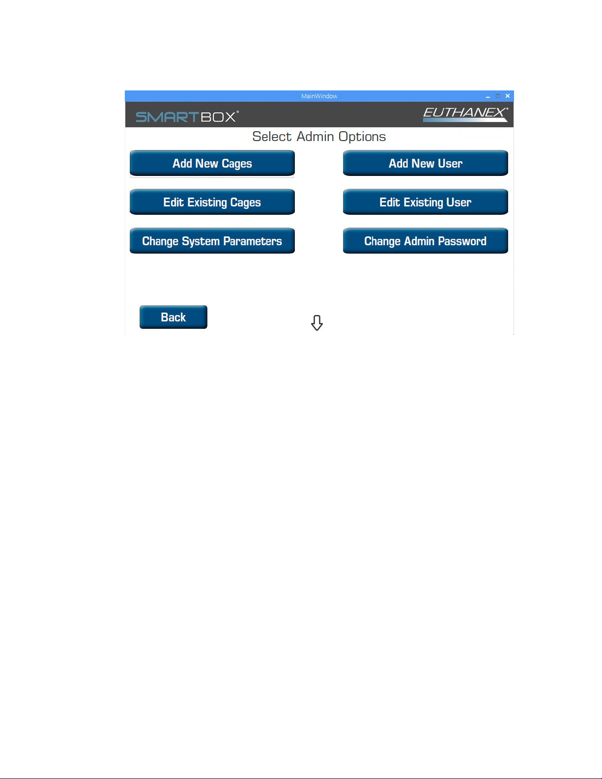
3. TheAdminOptionsScreenwillappear.
a. AddNewCage
i. UsethistoaddnewCagetypesforcycle.Thisincludessettingthecagesizeand
desiredflowratepercentage.
b. EditExistingCage(Willdisplaycurrentsettings)
i. Usetochangeoperatingparametersofdefinedcagesthatarealreadyinthe
system.
c. ChangeSystemParameters
i. Usetochangebasicsystemsettings.
d. AddNewUser
i. Setupnewusernameandpassword.
e. EditUser
i. Changeusernamesorpasswordsthatarealreadyinthesystem.
f. ChangeAdminPassword
g. Thedownarrowwilltakeyououtofthesoftwaretothedesktoptoallowforremote
serviceconnection.Pleasecontactsupport.

15
4. ToAddNewCage,selectfromadminscreen
a. Theaddnewcagescreenwillbedisplayed.
b.Typeinthelabelofthecagethatyouwanttoadd,thenhitnext.
c.Thecagedimensionsortotalvolumemustbeenteredonthisscreen.
Thesystemwillcalculateyourcagevolumebasedonthedimensionsspecified.
d.Wheninputiscompletepress"Next".

16
e.Thedesiredflowratepercentageneedstobesetforthenewcagetype.Usethe+/‐to
adjusttheflowpercentageyouwouldlike.Theunitcalculatesyourflowratebasedonthe
cagedimensionsthatwereenteredonthepreviousscreen.Press"Next"whenset.
f.Nowthetimesneedtobesetforthenewcage.Usethe+and–nexttothetimestobe
adjusted.
g.Ifasecondchargeisneeded,Usethe+and–nexttothetimestobeadjustedfor
secondchargeinputtimes.
h.Oncethesettingarecorrectpress"Save",anditwillreturntotheAdminscreen.
5. ToEditCage,selectfromAdminscreen
a. Selectthecagesthatyouwouldliketoeditfromthepop‐upmenu,thenhitok.

17
b. Thecurrentparametersfortheselectedcagewillbedisplayed.
c. Tomakechangesselect"Edit",andfollowtheinstructionsforaddinganewcage.

6. C
hangeSyste
m
a. Select
Setla
n
b. Scree
n
c. Elimin
d. Gasw
a
e. Ifyou
tocon
f. WIFIs
Select
g. Updat
h. Backu
p
these
t
asyo
u
i. When
A
m
Parameter
s
ifthesyste
m
n
guage,use
d
n
savertime
o
atesthegas
c
a
rningOn,th
needustoc
o
necttotheu
ettings.Use
d
thenetwork
e,usedtou
p
p
/Restore,
t
t
tingparame
u
areconnect
e
allchanges
a
s
,selectfrom
m
willrequire
d
tochoosed
e
o
utsetting.B
c
onnection
w
isadjuststh
e
o
nnecttoyo
u
nit.E
d
toconnect
t
andsecurity
p
datethePro
d
t
hesystemc
a
terswillbes
a
e
dtoWIFI.
a
remadesel
e
F
18
adminscree
apasswordf
e
siredinterf
a
w
arningoncy
c
e
timetoacti
v
u
runitforse
r
t
heunittoy
o
protocolthe
d
igysoftwar
e
a
nbebacked
a
ved.Youca
e
ctSave.
B
C
n
oruseroper
a
a
celanguage.
c
lerun.C
v
atethewar
n
r
vicesupport
,
o
urWIFInet
w
nenterthe
p
e
iftheuniti
s
uptoourse
r
nrestoreth
e
D
W
W
a
tion.AIfth
i
n
ingofnoga
s
,
thisistheI
D
w
ork.F
p
assword.Hi
t
s
connectedt
o
r
viceandsu
p
e
parameters
E
W
IFIisconn
e
W
IFIinNOT
c
i
sistunedof
f
s
flow.D
D
thatwewill
t
Save.
o
theinterne
p
portserver.
atanytimea
s
e
cted
c
onnected
f
then
need
t.
Allof
s
long

19
7. AddNewUser
a. Typeintheusernamethatyouwishtoadd.
b. Settheuserpassword.
i. SelectiftheuserwillhaveEmergencyStopbuttonduringthecycle.
ii. Selectifitwillrequireanadminpasswordtoengage.Ifyouselecttousesystem
password,thisopenstheoptionoflimitingthecagesthatausermayselector
operation
iii. OncecompletehitSave.
c. The"RequireAdminPasswordforemergencystop"flagifcheckedwillrequirethe
Administratorpasswordtobeenteredtostopacycle.Ifnocheckismadetheuserwill
beallowedtoinvokethestopwithnopasswordduringacycle.
NOTE:Ausercannotbesavedwithoutselectingcagesandcagequantitiesfortheuser.

20
d. Cagescanbeactivatedperuser,hitthe"Cages"icon.
e. Toactivateacage,placeachecknexttoallthecagesthattheuserwillhaveaccessto
whenloggedin.Hit"OK"tosave.
f. Thequantityofcagesthatcanbeselectedbythisusercanbelimitedbyselectingthe
g. "Quantity"button.
Table of contents
Other EUTHANEX Control Unit manuals


