EVA Logik ZW303 User manual

Federal Communications Commission (FCC) Statement
FCC Caution: Any changes or modifications not expressly approved by the party responsible for
compliance could void the user’s authority to operate this equipment.
This device complies with Part 15 of the FCC Rules. Operation is subject to the following two
conditions: (1) This device may not cause harmful interference, and (2) this device must accept any
interference received, including interference that may cause undesired operation.
NOTE: This equipment has been tested and found to comply with the limits for a Class B digital device,
pursuant to Part 15 of the FCC Rules. These limits are designed to provide reasonable protection
against harmful interference in a residential installation. This equipment generates, uses and can
radiate radio frequency energy and, if not installed and used in accordance with the instructions,
may caus harmful interference to radio communications.However, there is no guarantee that
interference will not occur in a particular installation. If this equipment does cause harmful interference
to radio or television reception, which can be determined by turning the equipment off and on,
the user is encouraged to try to correct the interference by one or more of the following measures:
Reorient or relocate the receiving antenna.Increase the separation between the equipment and
receiver.Connect the equipment into an outlet on a circuit different from that to which the receiver
is connected.Consult the dealer or an experienced radio/TV technician for help.This equipment
should be installed and operated with minimum distance 20cm between the radiator and your body.
IC Caution:
This device complies with Industry Canada licence-exempt RSS standard(s). Operation is subject
to the following two conditions: (1) this device may not cause interference, and (2) this device must
accept any interference, including interference that may cause undesired
operation of the device.
DECLARATION DE CONFORMITE D'INDUSTRIE CANADA
Ce périphérique a été testé et reconnu conforme aux limites spécifiées dans RSS-210.
Son utilisation est soumise aux deux conditions suivantes :
(1) il ne doit pas provoquer d'interférences gênantes et
(2) il doit tolérer les interférences re.ues, notamment cellessusceptibles d'en perturber le fonctionnement.
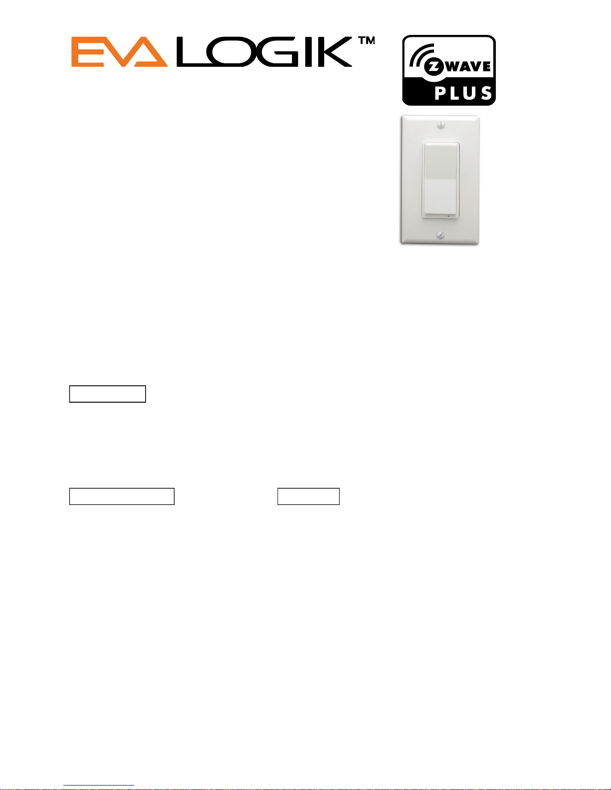
ZW303 Paddle On/Off Switch Manual
ZW303 Paddle On/Off Switch
WARRANTY
Show Home Products warrants this product to be free from manufacturing defects for
a period of two years from the original date of consumer purchase. This warranty is limited
to the repair or replacement of this product only and does not extend to consequential or
incidental damage to other products that may be used with this product.
This warranty is in lieu of all other warranties, expressed or implied. Some states do not
allow limitations on how long an implied warranty lasts or permit the exclusion or limitation
of incidental or consequential damage, so the above limitations may not apply to you.
This warranty gives you specific rights, and you may also have other rights which vary from
state to state. if the unit should prove defective within the warranty period.
SPECIFICATIONS WARNING
Model:ZW303
RISK OF FIRE
Power: 120 VAC, 60 Hz.
RISK OF ELECTRICAL SHOCK
Signal (Frequency): 908.42 MHZ.
RISK OF BURNS
Maximum load for outlet 8A, 600W Resistive
CONTROLLING APPLIANCES:
Maximum load for the Z-Wave controlled outlet:
EXERCISE EXTREME CAUTION WHEN USING Z-WAVE DEVICES TO CONTROL
600W Incandescent, ½ HP Motor or 1200W Resistive
APPLIANCES. OPERATION OF THE Z-WAVE DEVICE MAY BE IN A DIFFERENT
Range: Up to 100 feet line of sight between the Wireless Controller
ROOM THAN THE CONTROLLED APPLIANCE, ALSO ANUNINTENTIONAL ACTIVATION
and the closest Z-Wave receiver module.
MAY OCCUR IF THE WRONG BUTTON ON THE REMOTE IS PRESSED. Z-WAVE DEVICES
Operating Temperature Range: 32-104° F (0-40° C)
MAY AUTOMATICALLY BE POWERED ON DUE TO TIMED EVENT PROGRAMMING.
For Ourdoor use
DEPENDING UPON THE APPLIANCE, THESE UNATTENDED OR UNINTENTIONAL
Specifications subject to change without notice
OPERATIONS COULD POSSIBLY RESULT IN A HAZARDOUS CONDITION. FOR THESE
due to continuing product improvement
REASONS, WE RECOMMEND DO NOT RETURN THIS PRODUCT TO THE STORE
THE FOLLOWING:
Website:www.ishowlights.com
DO NOT USE Z-WAVE DEVICES TO CONTROL ELECTRIC
HEATERS OR ANY OTHER APPLIANCES WHICH MAY PRESENT
A HAZARDOUS CONDITION DUE TO UNATTENDED OR
UNINTENTIONAL OR AUTOMATIC POWER ON CONTROL.

Introduction:
The ZW303
is a Z-Wave enabled device and is fully compatible with any Z-Wave Plus enabled network.
around obstacles and radio dead spots to ensure that the signal is received at its intended destination.
ZW303 is a security enabled Z-Wave plus device. A security Enabled Z-Wave Plus Controller must be used in order to fully utilize the product.
Key Features:
---Remote ON/OFF control via the Z-Wave controller
---Manual ON/OFF control with the front panel push button
---Support Association Group and Auto Report switch status
---Support firmware upgrades via Over-the-air (need Gateways support)
Product Overview:
A. Up Push button
B. Down Push button
C. Load1 (Black)
D. Lin (Black) - Line in
E. Nin (White) - Nutral in
F. Load2 (Black)
ZW303 Installation Wiring Diagram
Key function description
Function 1: Press the up or down button to turn the output ON or OFF
Function 2: Press the up or down button three times quickly to ADD and REMOVE
Each module is designed to act as a repeater,which will re-transmit a radio frequency (RF) signal by routing the signal
A
B
F
Function 2: Press the up or down button three times quickly to ADD and REMOVE
Function 3: Press the up or down button six times quickly to change Status LED Configuration
Function 4: Press and hold the up or down button for 10 seconds to restore the device to the factory
Z-Wave Remote Control
ADD or Remove the ZW303 from the existing Z-Wave home control network with your primary controller.
---Refer to your primary controller instructions to process the inclusion / exclusion setup procedure.
Include ZW303 to/from a Z-Wave Gateway with supporting Security.The ZW303 can support the Primary Controller that implemented the security S2.
Notice: Including a node ID allocated by Z-WaveTM Controller means “Add” or “Inclusion”. Excluding a node ID allocated by
Z-WaveTM Controller means “Remove” or “Exclusion”.
z-wave protocol Command Class Node Info
COMMAND_CLASS_ZWAVEPLUS_INFO,
COMMAND_CLASS_VERSION,
COMMAND_CLASS_MANUFACTURER_SPECIFIC,
COMMAND_CLASS_DEVICE_RESET_LOCALLY,
COMMAND_CLASS_ASSOCIATION,
COMMAND_CLASS_ASSOCIATION_GRP_INFO,
COMMAND_CLASS_POWERLEVEL,
COMMAND_CLASS_SWITCH_BINARY,
COMMAND_CLASS_CONFIGURATION
COMMAND_CLASS_MULTI_CHANNEL_ASSOCIATION_V2,
COMMAND_CLASS_TRANSPORT_SERVICE_V2,
COMMAND_CLASS_SECURITY_2,
COMMAND_CLASS_SUPERVISION
The Below listed Command Class are all supported the Security S2
COMMAND_CLASS_VERSION,
COMMAND_CLASS_MANUFACTURER_SPECIFIC,
COMMAND_CLASS_DEVICE_RESET_LOCALLY,
COMMAND_CLASS_ASSOCIATION,
COMMAND_CLASS_ASSOCIATION_GRP_INFO,
COMMAND_CLASS_POWERLEVEL,
COMMAND_CLASS_SWITCH_BINARY,
COMMAND_CLASS_CONFIGURATION,
COMMAND_CLASS_MULTI_CHANNEL_ASSOCIATION_V2
---When prompted by your primary controller, click the Up or Down button three times in one second.
COMMAND_CLASS_MULTI_CHANNEL_ASSOCIATION_V2
COMMAND_CLASS_SUPERVISION

Z-Wave Configuration Parameters
1:
Locally Button function
Paramter No: 1(0x01) Size:1 Byte Value: 00(default) Up Button ON,Down Button OFF
Value: 01 Up Button OFF,Down Button ON
2:
Status LED Configuration
Paramter No: 2(0x02) Size:1 Byte Value: 00(default) Output ON,Led OFF.
Value: 01 OutputOFF,Led ON.
Value: 02 Always OFF
Value: 03 Always ON
3:
Count Down Configuration(Turn off the output by time
)
Paramter No: 3(0x03) Size:2 Byte Value: xx xx Turn off Output
Value Scope :0----36000S (default:00 00 no timer)
4:
Association Setting Parameter
Paramter No: 4(0x04) Size:1 Byte Value: 00 None Value: 01 Local(Defaul)
Value: 02 3-way Value: 03 3-way&Local
Value: 04 z-wave hub Value: 05 z-wave hub&Local
Value: 06 z-wave hub&3-way Value: 07 z-wave hub&Local&3-way
Value: 08 Timer Value: 09 Timer&Local
Value: 10 Timer&3-way Value: 11 Timer&3-way&Local
Value: 12 Timer&z-wave hub Value: 13 Timer&z-wave hub&Local
Value: 14 Timer&z-wave hub&3-way Value: 15 All
5:
Restores state after power failure
Paramter No: 5(0x05) Size:1 Byte Value: 00 Output OFF.
Value: 01 Output ON.
Value: 02 (default) The state before a power outage.
Support for Association Groups
ZW97 supports 3 association groups. A maximum of 5 node ID’s (nonmulti-channel devices) can be assigned to these association groups.
Association group_1:Z-Wave Plus Lifeline
Association group_1 is default to associate with the primary controller (Gateway/Hub/Controller) for ZW303 Status change report,
1. ZW303 will trigger AUTO report function if the Switch status had been changed.
2. When ZW303 high temperature alarm sends out notifications or releases notifications, ZW303 will auto report
You may use the below configuration parameters to change settings of the corresponding functionality.
2. When ZW303 high temperature alarm sends out notifications or releases notifications, ZW303 will auto report
Association group_2:basic set command
command. On (0xFF) or Off (0x00) to its associated group.
Restoring Factory Defaults
ZW
303
is removed from the network and will be restored to the factory setting
All Configuration Parameters values and Association information will be restored to factory default settings and excluded from the network.
Remark : All the setting and data will be permanently deleted.
Please use this procedure only when the network primary controller is missing or otherwise inoperable.
When the output of the ZW303 is changed, On (0xFF) or Off (0x00). The ZW303 will automatically send out a related basic set
Table of contents
Other EVA Logik Switch manuals
Popular Switch manuals by other brands

Nitek
Nitek VH439 Installation and operation manual

NVT Phybridge
NVT Phybridge PoLRE24 Quick install guide

Lucent Technologies
Lucent Technologies Cajun P333T quick start guide

TP-Link
TP-Link TL-SG2452 reference guide

Extron electronics
Extron electronics SW RGBHV Series user manual

Digital Equipment
Digital Equipment VNswitch 900EE Installation and configuration

Siemens
Siemens 3LD7 operating instructions

Pepperl+Fuchs
Pepperl+Fuchs RocketLinx ICRL2-U-16RJ45-G-DIN manual

Cisco
Cisco CBS 250 Series Get to know

Austin Hughes Electronics
Austin Hughes Electronics CyberView MU-IP3214 Specifications

Enabling Devices
Enabling Devices 605 user guide

B&B Electronics
B&B Electronics 232MSS2 user manual