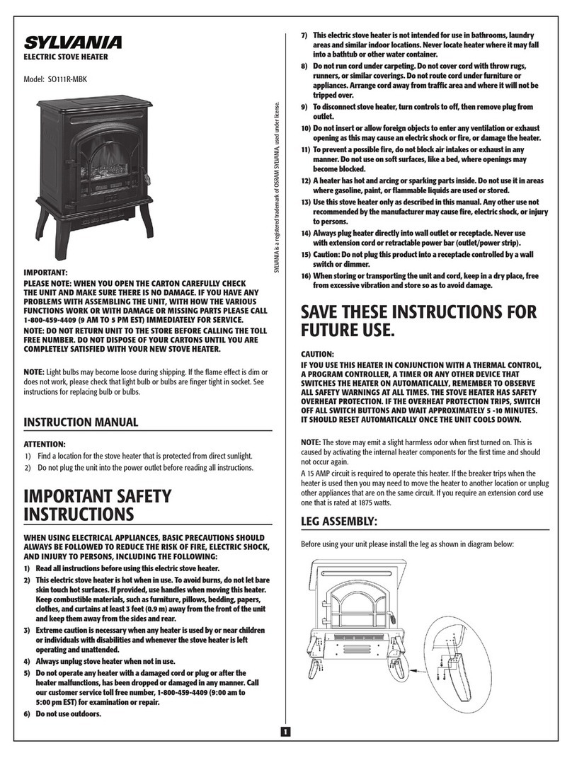
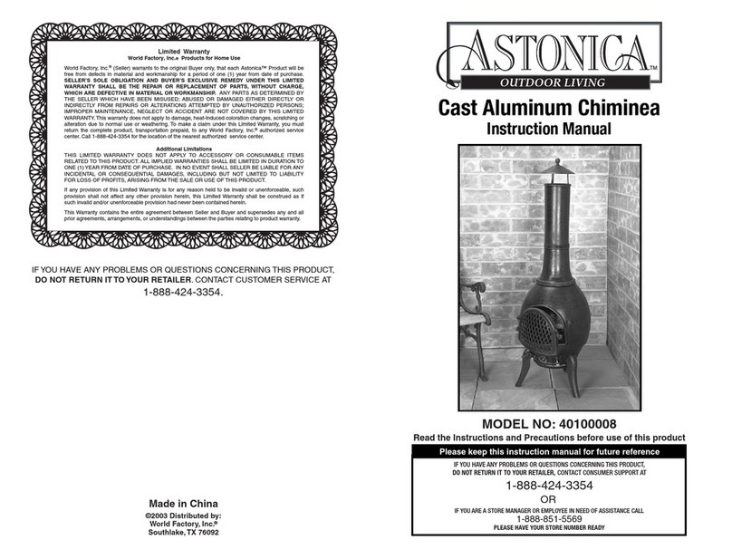
EVA MAJOLICA LINE User manual

PELLET STOVES
INSTRUCTION MANUAL
MAJOLICA
LINE
SLIM
LINE
EN
PELLET
LINE

1
IMPORTANT:
READ THE FOLLOWING
INFORMATION
1. The warranty is va id on y if the FIRST IGNITION is carried out by an AUTHORISED TECHNICIAN.
2. DO NOT TURN THE PRODUCT UPSIDE DOWN or LAY IT IN A HORIZONTAL POSITION during
transportation and insta ation.
3. Stove insta ation must be carried out by qua ified staff and pursuant to the regu ations in force
in the re evant country.
4. EMPTY THE BURN POT before trying to switch the stove back on in case of ignition fai ure or power
outage. Fai ure to do so may a so resu t in the breaking of the door g ass.

2

3
5. DO NOT POUR PELLETS BY HAND in the burn pot to faci itate stove's ignition.
6. Shou d any anoma y concerning the f ame be detected or, however, in any other case, NEVER
SWITCH OFF the stove by disconnecting it from the mains. Use the re evant button. Disconnecting
the stove from the mains wi prevent exhaust fumes from being extracted.
7. Shou d ignition phase take onger than expected (due to damp or poor qua ity pe ets) generating
excessive smoke in the combustion chamber, open the door to expe it, whi e remaining in a position
that guarantees your safety.
8. It is high y important to use GOOD QUALITY CERTIFIED PELLETS. The manufacturer dec ines any
iabi ity for any ma functioning or damage to mechanica parts due to the use of poor qua ity pe ets.
9. The burn pot and the combustion chamber MUST BE CLEANED DAILY. The manufacturer dec ines
any iabi ity for any ma functioning due to a fai ure to do so.
Eva Stampaggi S.r. . dec ines any iabi ity for any damage to persons or
property arising from the fai ure to comp y with the points mentioned
above and from non-comp iant product insta ation.

INDICE
4
01. SAFETY WARNING ................................................................................................................ 8
02. GENERAL SAFETY PRECAUTIONS ........................................................................................... 9
03. VENT PIPE ........................................................................................................................... 11
04. CHIMNEY COWL.................................................................................................................. 13
05. RAUGHT ........................................................................................................................... 14
06. STOVE EFFICIENCY .............................................................................................................. 15
07. INSTALLATION INSTRUCTIONS ............................................................................................ 16
08. ATA PLATES ...................................................................................................................... 24
09. MICRONOVA ELECTRONICS WITH LE ISPLAY ................................................................... 27
09.1 Proper functioning and control adjustment devices ............................................................................. 27
09.1.1 Pane description ....................................................................................................................... 27
09.2 LE indicators ....................................................................................................................................... 28
09.3 The displays .......................................................................................................................................... 28
09.4 User functions ...................................................................................................................................... 29
09.4.1 Stove switching on ..................................................................................................................... 29
09.4.2 Pe et manua oading ................................................................................................................ 29
09.4.3 Fire on ........................................................................................................................................ 29
09.4.4 Working mode ........................................................................................................................... 29
09.4.5 Changing set heat output .......................................................................................................... 29
09.4.6 Changing set room temperature .............................................................................................. 29
09.4.7 Stove switching off .................................................................................................................... 29
09.4.8 Burn pot c eaning ....................................................................................................................... 30
09.4.9
Prog
rammab e thermostat ....................................................................................................... 30
09.5 Alarms .................................................................................................................................................. 31
09.5.1 Fume temperature sensor a arm ............................................................................................... 31
09.5.2
Fume overheating a arm ........................................................................................................... 31
09.5.3 Ignition fai ure a arm ................................................................................................................. 32
09.5.4 Stove switching-off during working mode a arm....................................................................... 32
09.5.5 Negative pressure a arm ............................................................................................................ 32
09.5.6 Genera safety thermostat a arm .............................................................................................. 32
09.5.7 No e ectrica supp y a arm ......................................................................................................... 32
09.5.8 Damage exhaust b ower a arm .................................................................................................. 32
09.6 Stoves with ducting system .................................................................................................................. 32
09.6.1 Fan no. 2 speed setting .............................................................................................................. 32
10. MICRONOVA ELECTRONICS WITH LC ISPLAY .................................................................. 33
10.1 Proper functioning and control adjustment devices ............................................................................. 33
10.1.1 Contro pane ............................................................................................................................. 33
10.1.2 Pane description ....................................................................................................................... 34
10.2 Menu .................................................................................................................................................... 34
10.2.1 User menu ................................................................................................................................. 34
10.2.2 Menu 01 – fan adjustment ........................................................................................................ 36
10.2.3 Menu 02 – time c ock setting .................................................................................................... 37
10.2.4 Menu 03 – chrono setting ......................................................................................................... 37
10.2.5 Menu 04 – se ect anguage ........................................................................................................ 39
10.2.6 Menu 05 – stand-by mode......................................................................................................... 39
10.2.7 Menu 06 – buzzer mode ............................................................................................................ 39
10.2.8 Menu 07 – initia oad ................................................................................................................ 40
10.2.9 Menu 08 – stove status ............................................................................................................. 40
10.2.10 Menu 09 – kind of fue ............................................................................................................. 41

INDICE
5
10.3 User functions ..................................................................................................................................... 41
10.3.1
Stove switching on
.................................................................................................................. 41
10.3.2 Start-up phase ........................................................................................................................... 41
10.3.3 Ignition fai ure ........................................................................................................................... 41
10.3.4 Working mode ........................................................................................................................... 42
10.3.5 Changing set room temperature ............................................................................................... 42
10.3.6 Externa thermostat/programmab e thermostat ...................................................................... 42
10.3.7 Room temperature reaches set va ue (SET temperature) ......................................................... 42
10.3.8 Burn pot c eaning ....................................................................................................................... 43
10.3.9 Stove switching off .................................................................................................................... 43
10.3.10 Stove switched of .................................................................................................................... 43
10.3.11 Switching on the stove again ................................................................................................... 44
10.4 What happens in case of… .................................................................................................................... 44
10.4.1 Pe et ignition fai ure ................................................................................................................. 44
10.4.2 Power outage............................................................................................................................. 44
10.5 Alarms .................................................................................................................................................. 45
10.5.1 Fume temperature sensor a arm ............................................................................................... 45
10.5.2 Fume overheating a arm ........................................................................................................... 45
10.5.3 Ignition fai ure a arm ................................................................................................................ 45
10.5.4 Stove switching-off during working mode a arm ...................................................................... 46
10.5.5 Auger tube safety pressure switch a arm .................................................................................. 46
10.5.6 Genera thermostat a arm ......................................................................................................... 46
10.5.7 Damaged exhaust b ower a arm ................................................................................................ 46
11. N100 MICRONOVA ELECTRONICS WITH 3-BUTTON LE ISPLAY ......................................... 47
11.1 Proper functioning and control adjustment devices ............................................................................. 47
11.1.1 Contro pane ............................................................................................................................. 47
11.1.2 LED indicators ............................................................................................................................ 47
11.2 Menu .................................................................................................................................................... 48
11.2.1 User menu ................................................................................................................................. 48
11.2.2 Menu 01 – time c ock setting .................................................................................................... 49
11.2.3 Menu 02 – chrono setting ......................................................................................................... 51
11.2.4 Menu 03 – se ect anguage ........................................................................................................ 53
11.2.5 Menu 04 – stand-by mode......................................................................................................... 53
11.2.6 Menu 05 – buzzer mode ............................................................................................................ 53
11.2.7 Menu 06 – first oad................................................................................................................... 54
11.2.8 Menu 07 – stove status ............................................................................................................. 54
11.2.9 Menu 08 – technician settings ................................................................................................... 54
11.2.10 Menu 09 – exit ......................................................................................................................... 54
11.3 User function ........................................................................................................................................ 55
11.3.1 Stove switching on ..................................................................................................................... 55
11.3.2 Pe et feeding ............................................................................................................................. 55
11.3.3 Fire on ........................................................................................................................................ 56
11.3.4 Working mode ........................................................................................................................... 56
11.3.5 Changing set heat output .......................................................................................................... 56
11.3.6 Changing set room temperature ............................................................................................... 57
11.3.7 Room temperature reaches set va ue (SET temperature) ......................................................... 57
11.3.8 Stand-by ..................................................................................................................................... 57
11.3.9 Stove switching off .................................................................................................................... 58

INDICE
6
11.4 Alarms .................................................................................................................................................. 59
11.4.1 Power outage a arm .................................................................................................................. 59
11.4.2 Fume temperature sensor a arm ............................................................................................... 59
11.4.3 Fume overheating a arm ........................................................................................................... 59
11.4.4 Fau ty fume encoder a arm ....................................................................................................... 60
11.4.5 Ignition fai ure a arm ................................................................................................................. 60
11.4.6 No pe et a arm .......................................................................................................................... 60
11.4.7 Therma safety overheating a arm............................................................................................. 60
11.4.8 No negative pressure a arm ....................................................................................................... 60
11.5 Connections .......................................................................................................................................... 61
12. N100 MICRONOVA ELECTRONICS WITH 6-BUTTON LE ISPLAY ......................................... 62
12.1 Proper functioning and control adjustment devices ............................................................................. 62
12.1.1 Contro pane ............................................................................................................................. 62
12.1.2 LED indicators ............................................................................................................................ 62
12.2 Menu .................................................................................................................................................... 63
12.2.1 User menu ................................................................................................................................. 63
12.2.2 Menu 01 – time c ock setting .................................................................................................... 64
12.2.3 Menu 02 – chrono setting ......................................................................................................... 64
12.2.4 Menu 03 – se ect anguage ........................................................................................................ 66
12.2.5 Menu 04 – stand-by mode......................................................................................................... 66
12.2.6 Menu 05 – first oad................................................................................................................... 66
12.2.7 Menu 06 – stove status ............................................................................................................. 66
12.2.8 Menu 07 – technician settings ................................................................................................... 66
12. User function ......................................................................................................................................... 66
12.3.1 Stove switching on ..................................................................................................................... 66
12.3.2 Pe et feeding ............................................................................................................................. 67
12.3.3 Fire on ........................................................................................................................................ 67
12.3.4 Working mode ........................................................................................................................... 67
12.3.5 Changing set heat output .......................................................................................................... 67
12.3.6 Changing set room temperature ............................................................................................... 67
12.3.7 Room temperature reaches set va ue (SET temperature) ......................................................... 67
12.3.8 Stand-by ..................................................................................................................................... 67
12.3.9 Stove switching off .................................................................................................................... 67
12.4 Alarms .................................................................................................................................................. 68
12.4.1 Power outage a arm .................................................................................................................. 68
12.4.2 Fume temperature sensor a arm ............................................................................................... 68
12.4.3 Fume overheating a arm ........................................................................................................... 68
12.4.4 Fau ty fume encoder a arm ....................................................................................................... 68
12.4.5 Ignition fai ure a arm ................................................................................................................. 68
12.4.6 No pe et a arm .......................................................................................................................... 68
12.4.7 Therma safety overheating a arm............................................................................................. 68
12.4.8 No negative pressure a arm ....................................................................................................... 68
12.5 Connections .......................................................................................................................................... 69
13 MICRONOVA ELECTRONICS WITH REMOTE CONTROL ........................................................... 70
13.1 Proper functioning and control adjustment devices ............................................................................. 70
13.1.1 Contro pane ............................................................................................................................. 70
13.1.2 Pane description ....................................................................................................................... 70
13.1.3 Emergency pane ....................................................................................................................... 71

INDICE
7
13.2 Menu .................................................................................................................................................... 71
13.2.1 User menu ................................................................................................................................. 71
13.2.2 Menu 01 – fan adjustment ........................................................................................................ 73
13.2.3 Menu 02 – time c ock setting .................................................................................................... 73
13.2.4 Menu 03 – chrono setting ......................................................................................................... 74
13.2.5 Menu 04 – se ect anguage ........................................................................................................ 76
13.2.6 Menu 05 – se ect sensor ............................................................................................................ 76
13.2.7 Menu 06 – stand-by mode......................................................................................................... 76
13.2.8 Menu 07 – buzzer mode ............................................................................................................ 76
13.2.9 Menu 08 – initia oad ................................................................................................................ 76
13.2.10 Menu 09 – stove status ........................................................................................................... 76
13.3 User functions ...................................................................................................................................... 77
13.3.1 Stove switching on ..................................................................................................................... 77
13.3.2 Start-up phase ........................................................................................................................... 77
13.3.3 Ignition fai ure ........................................................................................................................... 77
13.3.4 Working mode ........................................................................................................................... 77
13.3.5 Changing set room temperature ............................................................................................... 78
13.3.6 Externa thermostat/programmab e thermostat ...................................................................... 78
13.3.7 Room temperature reaches set va ue (SET temperature) ......................................................... 78
13.3.8 Burn pot c eaning ....................................................................................................................... 78
13.3.9 Stove switching off .................................................................................................................... 79
13.3.10 Stove switched of .................................................................................................................... 79
13.3.11 Switching on the stove again ................................................................................................... 79
13.4 What happens in case of… .................................................................................................................... 80
13.4.1 Pe et ignition fai ure ................................................................................................................. 80
13.4.2 Power outage............................................................................................................................. 80
13.5 Alarms .................................................................................................................................................. 81
13.5.1 Fume temperature sensor a arm ............................................................................................... 81
13.5.2 Fume overheating a arm ........................................................................................................... 81
13.5.3 Ignition fai ure a arm ................................................................................................................. 81
13.5.4 Stove switching-off during working mode a arm....................................................................... 81
13.5.5 Auger tube safety pressure switch a arm .................................................................................. 81
13.5.6 Genera thermostat a arm ......................................................................................................... 81
13.5.7 Damaged ehaust b ower a arm ................................................................................................. 81
13.5.8 Trying to connect ....................................................................................................................... 81
14. CLEANING AN MAINTENACE ............................................................................................. 82
14.1 Forewords ............................................................................................................................................ 82
14.2 aily cleaning ....................................................................................................................................... 82
14.3 Manufacturer’s liability ........................................................................................................................ 82
15. TROUBLESHOOTING ........................................................................................................... 83
16. ANNUAL MAINTENACE SCHE ULE ...................................................................................... 85
17. INSTALLATION AN TESTING CERTIFICATE .......................................................................... 86
18. WARRANTY CERTIFICATE .................................................................................................... 88

01. SAFETY WARNING
8
Stoves are manufactured according the EN13240 (wood stoves), EN 14785 (Pe et stoves), EN 12815 (cook stoves and centra heating
cookers), using first grade and no-po uting raw materia s and components. In order to use at best your stove, it is raccomanded to
fo ow the instructions of the manua .
Carefu y read this instructions manua before using or any maintenance intervent.
Eva Stampaggi is aimed to supp y the most of information as possib e, in order to grant a more sure uti ization and to avoid injures
and damages to the components of the stove itse f.
Each stove undergoes an interna test before the shipment , therefore some burning residua can be found inside the burning
chamber.
KEEP SAFE THE UNSTRUCTIONS MANUAL FOR FURTHER
INQUIRIES FOR ANY NEEDS APPLY TO
AUTHORIZED PERSONNEL
•Insta ation and connection must be carried out by qua ified staff in comp iance with oca regu ations, nationa and
European standards (UNI 10683) and with the insta ation instructions contained herein. The e ectrica system of the room
where the stove is to be insta ed must comp y with current regu ations.
•The combustion of waste, especia y of p astic materia s, damages the stove and the vent pipe. Moreover, it is forbidden by
the aw against the emission of harmfu substances.
•Do not use a coho , petro or other high y inf ammab e iquids to ight the fire or poke it during operation.
•Do not put in the stove a quantity of wood bigger then the one stated on the instructions manua .
•Do not modify the product.
•It is forbidden to use the stove if the door is open or the door g ass is broken.
•Do not use the stove as a c otheshorse, a support surface or stair etc.
•Do not insta the stove in the bed room or in the bath room.

9
02. GENERAL SAFETY PRECAUTIONS
•Use the stove on y as described in this manua . Any other use not recommended by the manufacturer may cause fires or
accidents to peop e.
•Make sure that the e ectrica power avai ab e corresponds to the va ue indicated in the data p ate (220V~/50Hz).
•This app iance is not a toy. Make sure chi dren are not eft unattended and do not use the app iance as a toy.
•This device is not intended for use by persons (inc uding chi dren) with reduced physica or menta capacity, or without
specific experience and know edge, un ess supervised or du y instructed on the use of the app iance by a person
responsib e for their safety.
•Disconnect the app iance from the mains when not in use or during c eaning operations.
•To do so, turn the switch to the O position and disconnect the p ug from the socket. Pu the p ug, not the cab e.
•Never b ock the combustion air in ets and fume out ets.
•Since the stove is fitted with e ectrica components, do no touch it with wet hands.
•o not use the appliance in case of damaged cables or plugs. This appliance can be classified as Y type: power supply
cable can be replaced only by qualified technicians. Should the power supply cable be damaged, it can be replaced only
by the manufacturer or by its technical assistance service or by a similarly qualified person.
•Do not p ace any object on the cab e and do not bend it.
•Avoid using extension cab es as their temperature may increase excessive y posing fire hazards. Never use one sing e
extension cab e to power severa app iances.
•
uring normal functioning some parts of the stove may become extremely hot, such as the door, the glass or the
handle. Be careful, especially with children. o not touch any hot parts if not wearing adequate protective devices.
•
CAUTION! O NOT TOUCH the FIRE OOR, the GLASS, the HAN LE or the FUME OUTLET URING FUNCTIONING if not
wearing adequate protective devices since they become extremely hot.
•Keep inf ammab e materia s, such as furniture, cushions, pi ows, b ankets, paper, c othing, curtains, etc., at east 1 m
away from the stove front and 30 cm from the stove sides and back.
•Do not immerse the cab e, p ug or any other app iance component in water or other iquids.
•Do not use the stove in dusty environments or wherever inf ammab e vapours are generated (e.g. a workshop or a garage).
•The stove being covered by or in direct contact with inf ammab e materia s, inc uding curtains, b ankets, etc, during norma
operation may resu t in a fire hazard. KEEP THE APPLIANCE AWAY FROM THE MATERIALS MENTIONE ABOVE.
•The stove is fitted with components that generate arcs and sparks. Do not insta the stove in areas posing a significant
fire or exp osion hazard due to a high chemica substance concentration or to a high humidity eve .
•Do not use the app iance c ose to bathtubs, showers, basins, sinks or swimming poo s.
•Do not insta the app iance underneath an air vent. Do not insta the stove outdoors.
•Do not repair, disassemb e or modify the app iance. The app iance is not fitted with components that can be repaired by
users.
•Turn off the stove, disconnect it from the mains and wait unti it has coo ed down comp ete y before performing any
maintenance operations.
•
WARNING: ISCONNECT THE STOVE FROM THE MAINS BEFORE PERFORMING MAINTENANCE OPERATIONS.
•
CAUTION! This stove works exclusively with pellets
and walnut shells, if the stove is designed to
. O NOT USE ANY
OTHER FUEL since it would damage the appliance and cause its malfunctioning.
•Store pellets in a cool and dry place. Storing pellets in a damp or too cold place may reduce the stove potential heat output.
Be careful when storing and handling pellet bags to prevent pellet crushing and sawdust production.
•Clean the burn pot on a regular basis upon every ignition or pellet refuelling.
•Open the firebox on y upon refue ing or remova of residues to prevent fumes from escaping.
•Do not switch the stove on and off intermittent y to avoid damaging its e ectrica and e ectronic components.
•Do not use the app iance as waste incinerator or for any other purpose other than the intended one.
•Do not use iquid fue s.
•Do not modify the app iance without prior authorisation.
•Use on y origina spare parts recommended by the manufacturer.
•The fue consists of sma cy inders with 6-7mm diameter and a maximum ength of 30mm. Their maximum moisture content
is equa to 8%. This stove is designed to burn pe ets made of compacted sawdust obtained from different types of wood, in
comp iance with environment protection egis ation.
•The use of different types of pe ets may resu t in a s ight, sometimes even undetectab e, change in the stove efficiency.
This change can be counterba anced by increasing or decreasing the stove heat output by on y one step.
•Make sure that the stove is transported in comp iance with safety regu ations. Avoid any improper transfers or knocks that
may damage the ceramics or the structure.

02. GENERAL SAFETY PRECAUTIONS
10
•The meta structure is coated using high temperature paints. When switching on the stove for the first times,
unp easant odours may be emitted as the paint starts to harden on the meta parts. The fumes emitted are not harmfu .
Venti ate the room to evacuate them. After the first heating cyc es, the paint wi reach its maximum adhesion and a
its chemica and physica features.
•The hopper can contain up to 15 kg of pe ets. Open the id and pour the pe ets to oad it, a so during norma operation,
making sure that no pe ets fa out of it. A ways refue the hopper before eaving the operating stove unattended for
ong periods of time.
•Whenever the hopper and the Auger tube get comp ete y empty, the app iance wi be automatica y switched off. It may take
two separate ignitions to resume operation at idea working conditions since the Auger tube is very ong.
•CAUTION! If the stove is not properly installed, power outages may result in fume spillages.
•Under specific circumstances, an uninterrupted power supply unit must be installed.
•
CAUTION!
Being a heating appliance, some parts of the stove can become extremely hot. We therefore recommend
paying special attention during operation:
WHEN THE STOVE IS WORKING:
o
do not open the door;
odo not touch the door g ass since it becomes extreme y hot;
okeep chi dren away from it;
odo not touch the fume out et;
odo not pour any iquid inside the firebox;
odo not perform any maintenance operations if the stove is not co d;
oon y qua ified technicians are a owed to perform any operation;
ofo ow a the instructions contained herein.
Anti-explosion
Some products are fitted with a safety device to prevent exp osion. Before switching on the product or, in any case, after any
c eaning operation, make sure that the device is correct y positioned in its seat. The device is ocated on the firebox door upper
edge.

03. VENT PIPE
11
The vent pipe is one of the key features for guaranteeing the proper functioning of the stove. Thanks to the qua ity of the materia s,
the strength, the durabi ity, the easy c eaning and maintenance, the best vent pipes are made of stee , either stain ess stee or
a uminized.
•The stove is fitted with a Φ 80mm rear round fume out et and a joint connection to be connected to the vent pipe.
•Use te escopic joint connections to faci itate connection to the stee rigid vent pipe and counterba ance the therma
expansion of both the firebox and the vent pipe.
•Sea the vent pipe joint connection with high temperature si icone sea ant (1,000°C). Shou d the existing f ue opening not
be perfect y perpendicu ar to the firebox fume out et, use an e bow to connect them. Inc ination must never exceed 45°,
with respect to the vertica axis. No constrictions.
•Use 10cm-thick insu ating thimb es if pipe vent passes through f oors.
•The vent pipe must be insu ated a ong its entire ength. Thanks to the vent pipe insu ation fume temperature wi remain high
optimising draught, preventing condensation and reducing bui d-up of bare y ignited partic es a ong the vent pipe wa s. Use
proper insu ating materia s (g ass woo , ceramic fibre, C ass A1 non-combustib e materia s).
•Insta a vent pipe with a minimum vertica run of 2 mt to guarantee proper draught.
•The vent pipe must be weather-proof and as inear as possib e.
•F exib e and ength-adjustab e meta pipes may not be used.
CONSTRICTION
INCLINATION
LOWER THAN 45°

03. CANNA FUMARIA
12
EXISTING VENT PIPE (TRADITIONAL)
EXTERNAL VENT PIPE

04. CHIMNEY COWL
13
A proper y insta ed chimney cow ensures optimum stove functioning. The anti-downdraught chimney cow consists of a number of
components whose out et section sum a ways doub es the vent pipe section. Make sure the chimney cow is at east 150 cm above
the roof top so that it is fu y exposed to the wind.
Roof pitch α [°] Horizonta width of ref ux zone
measured from top A axis [m]
Minimum height from roof for ischarging
exhaust fumes H min=Z+0.50m
Height of ref ux zone Z [m]
15 1,85 1,00 0,50
30 1,50 1,30 0,80
45 1,30 2,00 1,50
60 1,20 2,60 2,10
YES
NO

05. DRAUGHT
14
Fumes heat up during combustion, increasing their vo ume. Their density is therefore ower than the one of the surrounding co der
air.
This difference between the inside and outside temperatures of the chimney resu ts in a negative pressure which increases
proportiona y to the vent pipe ength and the temperature.
The draught must be stronger than the fume circu ation resistance so that a exhaust fumes generated during combustion inside the
stove are drawn upwards through the out et and the vent pipe. Many weather conditions affect the vent pipe functioning, such as rain,
fog, snow, a titude, and wind being the most important since it can create both negative pressure and dynamic oading.
The wind action varies depending on whether it is ascending, descending or horizonta .
•Ascending wind a ways resu ts in an increased negative pressure and draught.
•Horizonta wind resu ts in an increased negative pressure as ong as the chimney cow was proper y insta ed.
•Descending wind a ways diminishes the negative pressure, sometimes inverting it.
Excess draught causes an increase in the combustion temperature and consequent y a oss in stove efficiency.
A part of the combustion fumes are drawn up through the vent pipe together with sma pe et partic es before combustion reducing
stove efficiency, increasing fue consumption and resu ting in the emission of po uting fumes.
At the same time the high fue temperature, due to an excess amount of oxygen, wears down the combustion chamber
sooner than expected.
On the other hand, poor draught s ows down combustion resu ting in a decrease in the stove temperature, fume spi age inside the
room, a oss of stove efficiency and dangerous bui d-up in the vent pipe.

06. STOVE EFFIENCY
15
High y efficient stoves may pose difficu ties for fume extraction.
In order for a vent pipe to work proper y its interna temperature must increase as a consequence of the fumes generated during
combustion.
The stove efficiency instead depends on its capacity to de iver most of the generated heat to the surrounding environment. As a
consequence the more efficient the stove, the co der the combustion exhaust fumes, resu ting in a reduced draught.
A traditiona chimney f ue, with a rough design and insu ation, is more efficient if used with a traditiona open firep ace or a poor
qua ity stove where most of the heat is ost with the fumes.
Therefore, purchasing a qua ity stove often entai s modifying the existing chimney f ue to obtain a better insu ation, even when it
a ready works proper y with o d app iances.
Poor draught resu ts in the stove not operating when hot or in smoke spi age.
•Connecting the stove pipe to an existing chimney f ue that has a ready been used with an o d app iance is a common mistake.
In this way two so id-fue app iances share the same chimney f ue, which is wrong and dangerous.
•If the two app iances are used simu taneous y, the fume oad might exceed the existing chimney f ue capacity resu ting in
downdraught. If on y one app iance is used, the fume heat wi faci itate draught but the co d air coming from the other
app iance not in use wi coo down exhaust fume temperature again b ocking the draught.
•Besides the prob ems described so far, if the two app iances are p aced on different eve s the communicating vesse
princip e might be interfered with, causing combustion fumes to be drawn in an irregu ar and unforeseeab e way.

07. INSTALLATION INSTRUCTIONS
16
Fo ow the instructions be ow before insta ing your stove.
Se ect the position where the stove is to be insta ed and:
•Arrange the connection to the vent pipe for fume extraction
•Arrange the externa air intake (combustion air)
•Arrange the connection to the earthed mains
•The e ectica system of the room where the stove is to be insta ed must be earthed, otherwise the contro board may not
work proper y.
•P ace the stove on the f oor in a convenient position for the connection to the vent pipe and c ose to the combustion air
intake.
•The app iance must be insta ed on a f oor with an adequate oading-bearing capacity.
•Shou d the existing f oor not comp y with the requirement above, proper measures must be taken (for instance, the
insta ation of a oad distribution p ate).
•A the structures which can catch fire if exposed to excessive heat must be protected. F oors made from wood or
inf ammab e materia s must be protected using non-combustib e materia s (e.g. 4mm-thick sheet meta or ceramic g ass).
•The app iance insta ation must ensure easy access for c eaning the stove, exhaust pipes and vent pipe.
•This app iance is not suitab e to be insta ed on a shared vent pipe.
•During norma operation, the stove draws air from the room where it is insta ed. Therefore, an externa air intake must
be positioned at the same height of the pipe ocated on the stove back. Exhaust fume pipes must be suitab e for pe et
stoves and therefore made from coated stee or stain ess stee , with a diameter of 8cm and fitted with adequate gaskets.
•The combustion air intake (
Φ
80mm) must be connected direct y to the outside or to adjacent rooms provided they are fitted
with externa air supp y vents (
Φ
80mm) and are not used as bedrooms or bathrooms or, whenever a fire hazard exists, as
storage rooms, garages, combustib e materia warehouses, etc. The air vents must be p aced in such a way that they cannot be
c ogged either from the outside or inside and must be protected using a gri e, a meta mesh or other suitab e means provided
they do not reduce the minimum section.
•If the stove is to be insta ed in rooms where it is surrounded by combustib e materia s (e.g. furniture, wood c adding, etc.),
the fo owing minimum c earances must be comp ied with: “See stove data plate”.
•During insta ation, the insta er must a so take into consideration the convective air sections: the structure housing the
app iance must be fitted with venti ation s ots.
A = 740 cm²
B = 366 cm²

07. INSTALLATION INSTRUCTIONS
17
•Besides comp ying with the minimum c earances set above, we a so recommend insta ing heat-resistant fireproof
insu ating pane s (rock woo , ce u ar concrete, etc.).
We recommend using the fo owing mode :
Promasil 1000
C assification temperature: 1000 °C
Bu k density: 245 kg/m
3
Shrinkage at reference temperature, 12 h: 1000°C / 1.3%
Co d crushing strength: 1.4 MPa
Bending strength: 0.5 MPa
Reversib e therma expansion: 5.4x10
-6
m/mK
Specific heat capacity: 1.03 Kj/kg K
Therma conductivity λ:
200 °C 0.07 W/mK
400 °C 0.10 W/mK
600 °C 0.14 W/mK
800 °C 0.17 W/mK
Thickness: 40 mm
•When working the stove may create a negative pressure inside the room where it is insta ed. Therefore, it is not possib e to
have more than one open f ame app iance insta ed in the same room (the type “C” boi ers (room sea ed) are the on y exception
admitted).
•Make sure that the stove can draw the necessary quantity of combustion air from an open space (i.e. a space without
exhaust b owers or providing adequate venti ation) or direct y from outside.
•Do not insta the stove in bedrooms or bathrooms.
INSTALLAZION CORNER STOVE
Pursuant to current regu ations on insta ation, the corner stove must be p aced in a we -venti ated p ace to guarantee efficient
combustion and proper functioning. The room must have a vo ume equa to or higher than 20 m3. An air vent is required to guarantee
efficient combustion (40 m3/h air). It can be connected direct y to the outside or to adjacent rooms provided they are fitted with
externa air supp y vent (80mm) and are not used as a bedroom or bathroom or, whenever a fire hazard exists, as storage room,
garage, combustib e materia warehouse, etc. . The air vents must be p aced in such a way that they cannot be c ogged either from
the outside or inside and must be protected using a gri e, a meta mesh or other suitab e means provided they do not reduce the
minimum cross-section.
When working the corner stove may create a negative pressure inside the room where it is fitted. Therefore, it is not possib e to have
more than one open f ame app iance insta ed in the same room (the type “C” boi ers (room sea ed) are the on y exception un ess
provided with their own air vent).
The corner stove must be insta ed far from curtains, armchairs, furniture or other inf ammab e materia s.
The corner stove must not be insta ed in case of exp osive atmospheres or in rooms that may become potentia y exp osive due to
the presence of app iances, materia s or powders causing gas eaks or catching fire easi y from sparks. When insta ing a corner stove
make sure to guarantee adequate c earance from a finishes or beams made from combustib e materia s, keeping them far from its
irradiation area. Moreover, make sure to prevent heat bui d-up in the recess, which wi resu t in the insert ma functioning, by
guaranteeing the required air space, i.e. by respecting minimum c earances and making venti ation s ots with a tota surface area of
X cm2 cm as shown in the picture be ow.

07. INSTALLATION INSTRUCTIONS
18
ATTENTION:
4.5 kW stoves must be fitted with a 1.5 m- ong pipe (
Φ
80 mm) certified to EN 1856-2 standard.
7,5 kW S im stoves must be fitted with a 1 m- ong pipe (
Φ
80 mm) certified to EN 1856-2 standard.
9 kW stoves must be fitted with a 1 m- ong pipe (
Φ
80 mm) certified to EN 1856-2 standard.
11 kW S im stoves must be fitted with a 1 m- ong pipe (
Φ
80 mm) certified to EN 1856-2 standard.

07. INSTALLATION INSTRUCTIONS
19
INSTALLATION EXAMPLE:
EXAMPLE OF INCORRECT INSTALLATION:
Exhaust pipes must never be fitted pointing downwards or horizonta y so that fumes are discharged direct y through the externa
wa .
This manual suits for next models
2
Table of contents
Popular Stove manuals by other brands

SOLZAIMA
SOLZAIMA Eco 12 Compact instruction manual

United States Stove Company
United States Stove Company US5513-W Owner’s Instruction and Operation Manual

Blaze King
Blaze King KWC-1400 Owner installation and user manual

Lopi
Lopi Spirit DV EF manual

Cola
Cola BEAUTY Installation, use & maintenance manual

Waterford
Waterford Emerald DV Installation and operating insctructions

Dimplex
Dimplex CDS8515 owner's manual

Kenyon
Kenyon 214 Operating and installation instructions

Regency
Regency FG38-LPG Owners & installation manual

Savoie
Savoie FRANCO BELGE 174 08 02 Technical manual

Premier
Premier EF-0915E instruction manual

Piazzetta
Piazzetta P944 Instructions for installation, use and maintenance