EVA 36-CR User manual

www.evaelektromekanik.com
CABLE CONNECTION CUBICLE
36kV
METAL ENCLOSED MODULAR SWITCHGEARS
(MMMH) USER GUIDE
Assembly, Operating and Maintenance Instructions
All manuals and user guides at all-guides.com

EVA ELEKTROMEKANİK SAN. VE TİC. LTD. ŞTİ.
DAĞYAKA MAH. 2008. CAD. NO:5 KAHRAMANKAZAN, ANKARA, TÜRKİYE
Tel: +90 312 811 27 27 Fax: +90 312 811 27 28
www.evaelektromekanik.com
All rights reserved. Any part of this catalogue can not be copied without the permission of the right holder. It can only be copied
and augmented with the written permission of EVA ELEKTROMEKANİK SAN. VE TİC. LTD. ŞTİ.
Switching The Future...
All manuals and user guides at all-guides.com

CONTENTS
1. GENERAL FEATURES 2
1.1 GENERAL SECTIONS 2
1.2 STANDARDS 2
1.3 CHARACTERISTIC FEATURES 3
2-LOADING - UNLOADING - TRANSPORTING 4
2.1 TRANSPORTING WITH FORKLIFT 4
2.2 TRANSPORTING OVER THE PIPE 4
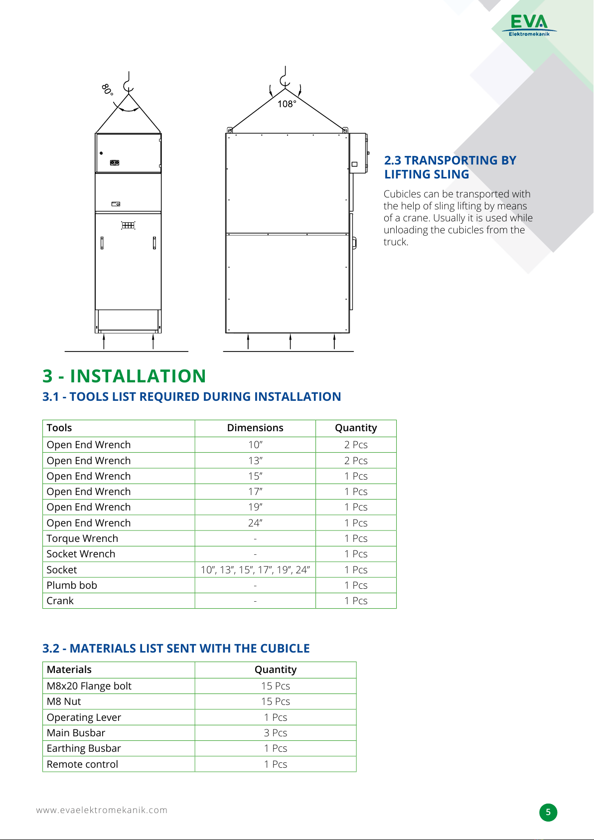
2.3 TRANSPORTING BY LIFTING SLING 5
3 - INSTALLATION 5
3.1 - TOOLS LIST REQUIRED DURING INSTALLATION 5
3.2 - MATERIALS LIST SENT WITH THE CUBICLE 5
3.3 - CUBICLE’S PLACEMENT 6
3.4 - CONNECTING THE CUBICLES TO EACH OTHER 7
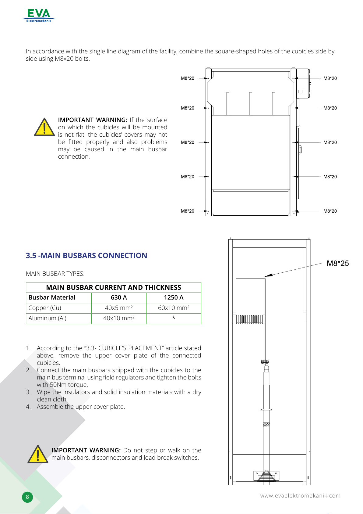
3.5 -MAIN BUSBARS CONNECTION 8
3.6 – EARTHING BUSBARS CONNECTION 9
3.7 - CONNECTING THE CUBICLES’ ARRAY TO THE MAIN GROUNDING SYSTEM OF THE FACILITY 9
3.8 –PASSAGES OF AUXILIARY SERVICE AND CONTROL CABLES FROM CUBICLE TO ANOTHER 10
3.9 - CONNECTION OF MV CABLES 11
3.10 - MATTERS TO BE CONSIDERED AGAINST INTERNAL ARC WHEN THE CUBICLE IS MOUNTED 11
4 - COMMISSIONING 12
4.1 - CHECKS TO BE PERFORMED BY THE BARE EYE 12
4.2 - MECHANICAL CHECKS 12
4.3 - SUPPLYING VOLTAGE TO THE MAIN BUSBAR AND REQUIRED CHECKS 12
4.4- OPERATING THE CABLE CONNECTION CUBICLE 12
4.5- SHUTTING DOWN THE CABLE CONNECTION CUBICLE 12
5 - MAINTENANCE INSTRUCTIONS AND RECOMMENDATIONS FOR THE AIR
INSULATED METAL ENCLOSED CUBICLES MMMH TYPE 13
5.1-MAIN BUSBAR COMPARTMENT 13
5.2 LIST OF TOOLS REQUIRED DURING MAINTENANCE AND INSTALLATION 13
6 - GUARANTEE TERMS 13
All manuals and user guides at all-guides.com

www.evaelektromekanik.com
2
1- GENERAL FEATURES
eva-36-CR is an sf6 gas insulated switchgear used for medium voltage distribution networks. eva-36-CR, and as
desired, can be supplied in a combined form. By performing all the required tests and the related quality control
processes to all the modulars, the products will be ready for delivery and installation.
1.1 GENERAL SECTIONS
eva-36-CR SWITCHING SYSTEM IS FULLY COMPLIANT WITH TS EN / IEC 62271-1, TS EN / IEC 62271-200 STAN-
DARDS. ALSO, THIS SWITCHING SYSTEM HAS A PROTECTION CLASS OF IP3X ACCORDING TO TS EN / IEC 60529
STANDARDS.
TO INSTALL, OPERATE AND MAINTAIN THIS EQUIPMENT SAFELY, TSE AND IEC REGULATIONS MUST BE FOL-
LOWED.
1.2 STANDARDS
All manuals and user guides at all-guides.com

www.evaelektromekanik.com
3
Rated Voltage (kV) 36
Type eva-36-CR
Main Busbar Rated Current (A) 630 – 1250
Feeder Rated Current 630 – 1250
Rated power frequency withstand voltage
(KV rms)
70
Rated Lightning Impulse Withstand Voltage (kV) 170
Rated Short Circuit Withstand Current (rms) 16kA / 1sec
Rated Peak Withstand Current (kA-Peak) 40
Loss of Service Continuity Class LSC 2A – PI *
Internal Arc Classication (Cable Connection
and Main Busbar)
IAC – A(FL) 16kA / 1sec
Protection Level (TS 3033 EN 60529) IP3X
Applied Standard TS EN / IEC 62271-1, TS EN / IEC 62271-200
Height (mm) 2250
Width (mm) 750
Depth (mm) 1400
1.3 KARAKTERİSTİK ÖZELLİKLER
* LSC 2A - PI DESCRIPTION
LSC 2A Loss of Service Continuity
2A When Interfering to the Accessible Part of a Cubicle like the Cable Connection Compartment and
de-energizing it, Neighboring Cubicles May Be Still Energized. In other words, Service Continuity is
Not Restricted.
PI P: There Are Multiple Sections.
I: These Sections Are Separated From Each Other By Insulating Material.
All manuals and user guides at all-guides.com

www.evaelektromekanik.com
4
2- LOADING - UNLOADING - TRANSPORTING
Loading, unloading and transporting methods of the MMMH type cubicles are shown below:
Cubicles can be carried either way as shown in the the pictures below. In addition, forklift is usually
used to unload the cubicles from the truck and transport them to the assembly site.
2.1 TRANSPORTATING WITH FORKLIFT
Pipe Transporting is used to line up and dock the cubicles. Never use Cranks while transporting the cubicles.
2.2 TRANSPORTING OVER THE PIPE
All manuals and user guides at all-guides.com

www.evaelektromekanik.com
5
Cubicles can be transported with
the help of sling lifting by means
of a crane. Usually it is used while
unloading the cubicles from the
truck.
2.3 TRANSPORTING BY
LIFTING SLING
3 - INSTALLATION
3.1 - TOOLS LIST REQUIRED DURING INSTALLATION
3.2 - MATERIALS LIST SENT WITH THE CUBICLE
Tools Dimensions Quantity
Open End Wrench 10’’ 2 Pcs
Open End Wrench 13’’ 2 Pcs
Open End Wrench 15’’ 1 Pcs
Open End Wrench 17’’ 1 Pcs
Open End Wrench 19’’ 1 Pcs
Open End Wrench 24’’ 1 Pcs
Torque Wrench -1 Pcs
Socket Wrench -1 Pcs
Socket 10’’, 13’’, 15’’, 17’’, 19’’, 24’’ 1 Pcs
Plumb bob -1 Pcs
Crank -1 Pcs
Materials Quantity
M8x20 Flange bolt 15 Pcs
M8 Nut 15 Pcs
Operating Lever 1 Pcs
Main Busbar 3 Pcs
Earthing Busbar 1 Pcs
Remote control 1 Pcs
All manuals and user guides at all-guides.com

www.evaelektromekanik.com
6
• Place the MMMH Type cubicle on a channel inside
the building in accordance with the dimensions
indicated in the right picture.
•
• A 5cm gap should be left between the placed
cubicles on the right or the left side inside the
building and the wall.
•
• Close the channel gaps.
•
• Do not go below the dimensions indicated in the
right picture.
3.3.1 Placement inside the Building:
3.3 - CUBICLE’S PLACEMENT
• Base holes that enable the cubicles to be xed to the ground are provided as shown in the below picture.
• Fix the cubicles to the ground by using M10 steel peg or iron dowel.
• The dispatched cubicles should
be placed on the side and
according to the illustrated
gure.
• Do not go below the provided
dimensions.
• The building dimensions can be
determined accordingly.
• The gaps between the cubicles
from one side and the ceiling
and the back wall from the other
side should be at least 300mm
and 100mm respectively.
IMPORTANT WARNING:
All manuals and user guides at all-guides.com

www.evaelektromekanik.com
7
3.4 - CONNECTING THE CUBICLES TO EACH OTHER
The lower holes dimensions are provided in the picture below. Based on these dimensions a steel peg or an iron
dowel should be used. Then the holes to be xed with M10x50 bolts.
MV Cable Entry Point
Pull the lifting hooks upwards (See below pictures). Bring the cubicles to the settlement area by using the relevant
transport apparatus and taking into consideration the “Loading - Unloading Transporting” instructions.
THE BASE METAL HOLE DIMENSIONS OF THE CUBICLE
All manuals and user guides at all-guides.com

www.evaelektromekanik.com
8
In accordance with the single line diagram of the facility, combine the square-shaped holes of the cubicles side by
side using M8x20 bolts.
1. According to the “3.3- CUBICLE’S PLACEMENT” article stated
above, remove the upper cover plate of the connected
cubicles.
2. Connect the main busbars shipped with the cubicles to the
main bus terminal using eld regulators and tighten the bolts
with 50Nm torque.
3. Wipe the insulators and solid insulation materials with a dry
clean cloth.
4. Assemble the upper cover plate.
IMPORTANT WARNING: If the surface
on which the cubicles will be mounted
is not at, the cubicles’ covers may not
be tted properly and also problems
may be caused in the main busbar
connection.
3.5 -MAIN BUSBARS CONNECTION
MAIN BUSBAR TYPES:
MAIN BUSBAR CURRENT AND THICKNESS
Busbar Material 630 A 1250 A
Copper (Cu) 40x5 mm260x10 mm2
Aluminum (Al) 40x10 mm2*
IMPORTANT WARNING: Do not step or walk on the
main busbars, disconnectors and load break switches.
All manuals and user guides at all-guides.com

www.evaelektromekanik.com
9
Connect the grounding busbar points of the two adjacent
cubicles with a copper conductor that is already provided with
the cubicle using bolts as shown in the right picture (3).
GROUNDING
CONNECTION
POINT
• To connect the cubicle’s array to the facility’s main
grounding system, use the grounding busbar located in the
cable connection compartment of the cubicles. See Picture
(4).
• Any of the cubicles at the beginning or at the end of the
cubicle’s array can be used for this purpose.
3.6 – EARTHING BUSBARS CONNECTION
3.7 - CONNECTING THE CUBICLES› ARRAY TO THE MAIN GROUNDING SYSTEM
OF THE FACILITY
IMPORTANT WARNING: Check thoroughly that the
grounding busbars of all the cubicles found in the
cubicle’s array are connected to each other.
All manuals and user guides at all-guides.com

www.evaelektromekanik.com
10
3.8 –PASSAGES OF AUXILIARY SERVICE AND CONTROL CABLES FROM CUBICLE TO
ANOTHER
• The sockets in the LV cabinet are used for the passage of
auxiliary service and control cables from cuibcle to another.
See the left picture (5).
• Take either the female or the male socket found on the
cable passage hole in the LV cabinet and connect it to its
corresponding socket found on the cable passage hole of
the next cubicle. See the left picture (6).
NOTE: The connection between cubicle to another
is made by combining the cable entry sockets that
contain the electrical interlock and AC-DC cables
to each other.
NOTE: The cable passage hole found at the very beginning or at the end of the cubicle’s array is used
for the passage of the auxiliary service, control and command cables coming from the external power
supplies.
IMPORTANT WARNING: If there is a battery rectier
group in the facility, ensure that is connected to a 220 /
230 VAC source.
PROTECTION AND CONTROL
CABINET
PASSAGES OF CONTROL CABLES
FROM CUBICLE TO ANOTHER
SOCKETS’
PASSAGES
All manuals and user guides at all-guides.com

www.evaelektromekanik.com
11
3.9 - CONNECTION OF MV CABLES
3.10- MATTERS TO BE CONSIDERED AGAINST INTERNAL ARC WHEN THE CUBICLE IS
MOUNTED
MV CABLES CONNECTION
MV Cables are made according to the cable terminal cap instructions.
The plastic plugs found at the cubicle’s bottom surface should be
adjusted in accordance with the cables diameter so to enable the cables
from passing through them. See picture (8).
1. Open the cubicle’s cable connection compartment door.
2. Mount the cable terminal caps ( internal type ) on the MV cable
terminals in accordance with the related instructions.
3. Connect the mounted terminals to the cubicles’s output terminals.
See picture (7).
4. Connect the metallic screen of the MV cables to the cubicle’s
earthing busbar.
5. Fix the MV cables by using the cable supporting points located on
the MV cables’ entrance of the cubicle. See pictutre (8).
Close the cubicle’s side by cover plates before the operating.
All manuals and user guides at all-guides.com

www.evaelektromekanik.com
12
4.1 - CHECKS TO BE PERFORMED BY THE BARE EYE (Checks to be Performed While the Main
Busbar is De-energized)
4.2 - MECHANICAL CHECKS (Checks to be Made in This Section Should Be Performed While
the Main Busbar is De-energized.)
IMPORTANT WARNING: Never connect the MV cables connected to the output terminal in a way that will
force the output terminals to pull down.
4 - COMMISSIONING
If a cubicle array will be formed by arranging various types of MMMH cubicles side by side and the commissioning
wil be performed for the rst time, it is recommended by our company to apply the following procedure:
1. Check whether the connections of the cubicles’ main busbar are connected along with the disconnector or the
load break switch or not and tighten the loose bolts and nuts if required. While checking the connectivity, be
careful from damaging the bushings of the disconnector or the load break switch. Never step or walk on the
busbar, disconnector or the load breaker switch
1. Perform “Commissioning”, “De-commissioning” and the “Accessibility to Cable Connection Compartment” for
each cubicle in accordance with the operating instructions sticked on them. During that, check the mechanical
interlocks are operating properly and no problems are occured.
2. Please contact EVA ELEKTROMEKANİK on (0090 312 811 2727) if any problem is encountered during the above
points.
2. Check if there is any unusual object inside the cubicle and take it out.
3. Check that there is at least 100 mm gap between the cubicles’ back and the building’s wall and that there is no
objects in between.
4. Check whether the side cover plates used against the internal arc are xed, if not x them so.
5. If there is a battery rectier group in the facility, ensure that is connected to a 220 / 230 VAC source.
6. Ensure the grounding system of the cubicles by checking the grounding busbars of the cubicles’ array
which must be properly and tightly connected to each other. Also, ensure the cubicles’ grounding system by
checking the earthing busbar of the rst or the last cubicle which must be connected to the external earthing
system by an earthing conductor.
7. Check the connections of the LV cabinet.
4.3 - SUPPLYING VOLTAGE TO THE MAIN BUSBAR AND REQUIRED CHECKS
4.4- OPERATING THE CABLE CONNECTION CUBICLE
4.5- SHUTTING DOWN THE CABLE CONNECTION CUBICLE
1. By Switching o the switching elements of the incoming cubicle, energize the main busbar and wait for 90 to
120 minutes.
2. Ensure that the voltage indicators lamps of the incoming cubicle are o.
3. If no problems were observed then energize the cubicles one by one as stated below.
4. After energizing the cubicle’s array, check whether if there is unusual noise or not.
1. If the Cable Connection Compartment door of the Cable Connection Cubicle is Open, CLOSE it.
2. Switch o the output feeder feeding the cubicle.
3. Ensure the voltage indicator lamps are on.
1. Switch on the output feeder feeding the cubicle.
2. Ensure the voltage indicator lamps are o.
All manuals and user guides at all-guides.com

www.evaelektromekanik.com
13
Üst Kapak Sacı
5.1-MAIN BUSBAR COMPARTMENT
1. Check whether the connections of the cubicles’ main
busbar are connected along with the disconnector or
the load break switch or not and tighten the loose bolts
and nuts if required. While checking the connectivity, be
careful from damaging the bushings of the disconnector
or the break switch. Never step or walk on the busbar
and the disconnector or the load breaker switch.
To nd the main busbar, remove the bolted connections
of the covers found on the upper part of the cubicles.
5 - MAINTENANCE INSTRUCTIONS AND RECOMMENDATIONS FOR
THE AIR INSULATED METAL ENCLOSED CUBICLES MMMH TYPE
5.2 LIST OF TOOLS REQUIRED DURING MAINTENANCE AND INSTALLATION
Tools Dimensions Quantity
Dirt Chemical Solution - -
Clean Cloth - -
Open End Wrench 10’’, 13’’, 15’, 17’’, 19’’, 24’’ 2 Pcs
Torque Wrench -1 Pcs
Socket Wrench -1 Pcs
Socket 10’’, 13’’, 15’, 17’’, 19’’, 24’’ 1 Pcs
The manufacturer company guarantees the product against any material and operational defects for a period of
2 years within the conditions specied in the contract. In this 2-years period, if any malfunction is detected within
the conditions specied in the contract, the manufacturer company may seek repair and / or replacement of the
faulty products. Improper storage, use or repair of the equipment by the user other than the conditions specied
in this user manual, constitutes a breach of the warranty and causes it to be null.
6 - GUARANTEE TERMS
IMPORTANT WARNING: Before starting the maintenance work; the Cubicles and the Main Busbar must
be DE-ENERGIZED and the GROUNDING must be taken too.
All manuals and user guides at all-guides.com

NOTES:
All manuals and user guides at all-guides.com

Switching The Future...
All manuals and user guides at all-guides.com

EVA ELEKTROMEKANİK SAN. VE TİC. LTD. ŞTİ.
DAĞYAKA MAH. 2008. CAD. NO:5
KAHRAMANKAZAN, ANKARA, TÜRKİYE
Tel: +90 312 811 27 27 Fax: +90 312 811 27 28
www.evaelektromekanik.com satis@evaelektromekanik.com
METAL ENCLOSED MODULAR SWITCHGEARS
(MMMH) USER GUIDE
All manuals and user guides at all-guides.com
Table of contents
Other EVA Switch manuals