Evak E Series Instructions for use

2

3
Instruction Manual
2.5" & 3" Full Free Passage Submersible Sewage Pump
HIPPO DN65/80 Series
Item Specifications
Liquid handled Type Sewage, waste water, miscellaneous drain water
Temperature Non-Automation 1.5~5.5 HP 0~40°C (32~104°F)
Automation 1.5~2 HP 0~40°C (32~104°F)
Materials Pump Casing EN-GJL-200
Impeller
Shaft AISI 410 stainless steel
Motor type Dry type submersible motor
Shaft seal lubrication oil Turbine No.32 ISO VG-32
Maximum water depth 10m (33ft)
EN-GJL-200
Introduction
Check the following points upon receipt of your pump:
> Is the pump exactly what you ordered? Check nameplate. It is especially important that you check
whether the pump is to be used with 50 or 60 Hz.
> Has any damage occurred during shipment? Are any bolts or nuts loose?
> Have all necessary accessories been supplied? (For a list of standard accessories see Construction.)
We recommend that you keep a spare pump on hand in case of emergencies.
Keep this instruction manual in a place for future reference.
Specifications
Check the nameplate for your pump’s head, discharge volume, speed (R.P.M), motor voltage
and current.
Other specifications are noted in the chart below.
INDEX
Introduction……………...…………..PAGE. 3
Specifications………………….…….PAGE. 3
Installation……….…………………...PAGE. 4
Electrical wiring……………………...PAGE. 4
Operation………..………………...…PAGE. 5
Maintenance……………….…………PAGE. 5
Construction (HIPPO DN 1.5~2HP)…...…....PAGE. 6
Construction (HIPPO DN 3HP)……............PAGE. 8
Construction (HIPPO DN 4~5.5HP)……......PAGE. 10
Disassembly and Assembly…………….PAGE. 12
Nameplate format………………………..PAGE. 13
Troubleshooting…………………….……PAGE. 14
4
H2
H1
off
on
Installation
1. Check the following before beginning installation.
Insulation resistance measurement:
With the motor and cable (excluding the power supply cable) immersed in water, use a Megger to measure the insulation
resistance between ground and each phase of the motor, and again between each phase of the motor. The Megger should
indicate an insulation resistance of not less than 20mega ohms. While making the measurement, keep the power supply ca-
ble off the ground.
We recommend that an auxiliary pump be kept on hand in case of emergency.
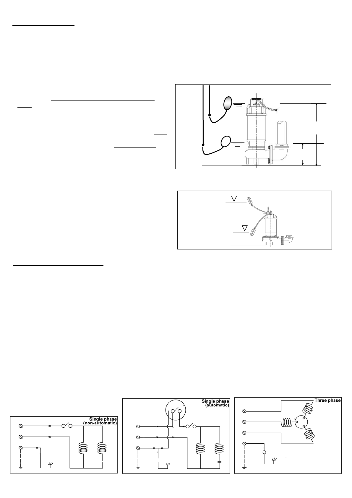
2. Installation
Fig-1
Fig-2
Operating Water Level
Stop Water Level
H1: Lowest water level (Motor flange)
H2: Operating water level
This must be above the top of the motor
1.! WARNING : Under no circumstances should cable be
pulled while the pump is being transported or installed.
Attach a chain or rope to the grip and install the pump.
2.This pump must not be installed on its side or operated a dry
condition. Ensure that it is installed upright on a secure base.
3.Install the pump at a location in the tank where there is the least
turbulence.
4. If there is a flow of liquid inside the tank, support the piping
where appropriate.
5.Install piping so that air will not be entrapped. If piping must be
installed in such a way that air pockets are unavoidable, install
an air release valve wherever such air pockets are most likely to
develop.
6.Do not permit end of discharge piping to be submerged, as
backflow will result when the pump is shut down.
7..! WARNING : Non-automatic pumps do not have an automatic
operating system. Do not operate the pump for a long time with
the water level near the lowest water level(H1) as shown in
Fig.1, as the automatic cut-off switch incorporated inside the
motor will be activated.
8.To avoid dry operation, install an automatic operating system so
that this will not happen, as shown in Fig.2 and maintain a safe
operating water level.
Electrical wiring
1.Wiring
A) Wire as indicated for the appropriate start system as shown in Fig-3 & 4 for singlephase version and Fig-5 for three phase.
B) Loose connections will stop the pump. Make sure all electrical connections secure.
C) For three phase motors - Operate the pump for a short time (1 or 2 seconds) to verify the rotation of direction of the impeller, if its recoil
is in counterclockwise direction, the direction of its rotation is correct. If not please switch two of the three power cords to correct the
rotation of direction of the impeller.
D) Make sure to check the pump’s direction of rotation with the pump exposed to the atmosphere. Operating the pump with reversed rota-
tion while in submerged condition under water will most likely to damage the pump, which may lead to leakage and electrical shock.
2.Cable
WARNING : Never let the end of the cable contact water.
A) If the cable is extended, do not immerse the splice in water.
B) Do not pull the cable.
C) Install the cable so that it will not overheat. Overheating is caused by coiling the cable and exposing it to direct sunlight.
3.Grounding
To ground the green (yellow/green) wire. Under no circumstances should the green (yellow/green) wire be connected to the power sup-
ply directly.
4. WARNING : Use short circuit breakers to prevent danger of electrical shock.
5. WARNING : Never start the pump while it is suspended, as thepump may jerk and cause serious accident involving injury.
Fig-3 Fig-4 Fig-5
Black
Green
White
Red
(Yellow/Green)
(Green/Yellow)
Frame grounding
Ground
Overload protector
R
S
T
PE
U
V
W
U2
W2
V2
Black
(Brown)
(Blue)
White
Green
(Yellow/Green)
Frame grounding
Ground (Green/Yellow)
Thermal
Protector
L
N
PE
Main
Auxiliary
(Yellow/Green)
Capacitor
Black
(Brown)
(Blue)
White
Green
Frame grounding
Ground (Green/Yellow)
Thermal
Protector
L
PE
Main
Auxiliary
N
Thermal
Protector
Black
(Brown)
(Blue)
White
Green
(Yellow/Green)
Ground (Green/Yellow)
Frame grounding
Main
Auxiliary
Capacitor
(Green/Yellow)
PE
Float Switch

5
Operation
Maintenance
Motor output 1.5HP 2HP 3HP 4HP 5.5HP
Mechanical seal 15Ø 20Ø
Lip seal 15Øx 24Øx7 t
Oil filler plug O-ring (Inner diameter) x (outer diameter) x (thickness) = 7.52Øx14.5Øx3.53 t
Lubricating oil
(turbine oil #32) 280 cc 500 cc
20Øx 38Øx7 t
Check pressure, output, voltage, current and other specifications. Unusual readings may indicate.
Refer to Troubleshooting and correct as soon as possible.
1. Daily inspections
Check current and ammeter fluctuation daily. If ammeter fluctuation is great, even though within the limits of pump
rating, foreign matter may be clogging the pump. If the quantity of liquid discharged falls suddenly, foreign matter
may be blocking the suction inlet.
2. Regular inspections
a. Monthly inspections
Measure the insulation resistance. The value should be more than 1M ohm. If resistance starts to fall rapidly even with
an initial indication of over 1M ohm, this nay be an indication of trouble and repair work is required.
b. Annual inspections
To prolong the service life of the mechanical seal by replacing the oil in the mechanical seal chamber once a year. Wa-
ter mixed the oil or cloudy textures are indications of a defective mechanical seal requiring replacement. When replac-
ing the oil, lay the pump on its side with filler plug on top. Inject suitable amount turbine oil No.32 (ISO VG-32) .
c. Inspections at 3-5year intervals
Conduct an overhaul of the pump. These intervals will preclude the possibility of future trouble.
3. Parts that will need to be replaced
Replace the appropriate part when the following conditions are apparent.
Replaceable part Mechanical seal Oil filler plug O-ring Lubricating oil O-ring
Replacement guide Whenever oil in
mechanical seal
chamber is clouded
Whenever oil is replaced
or inspected Whenever clouded or dirty Whenever pump is
overhauled
Frequency Annually A half yearly A half yearly Annually
Note: above replacement schedule is based on normal operating conditions.
1. Before starting the pump
a. After completing installation, measure the insulation resistance again as described in Installation.
b. Check water level.
If the pump is operated continuously for an extended period of time in a dry condition or at the lowest water
level, the motor protector will be activated. Constant repetition of this action will shorten pump service life. Do
not start the pump again in such a situation until after the motor has completely cooled.
2. Test operation….
Non-automatic pump
Automatic pump
a. Turn the operating switch on and off a couple of times to check for normal pump start.
Floating switch must be raised for the pump to start.
b. Next, check direction of rotation. If discharge volume is low or unusual sounds are heard when the pump is op-
erating, rotation has been reversed. When this happens, reverse two of the wires.

6
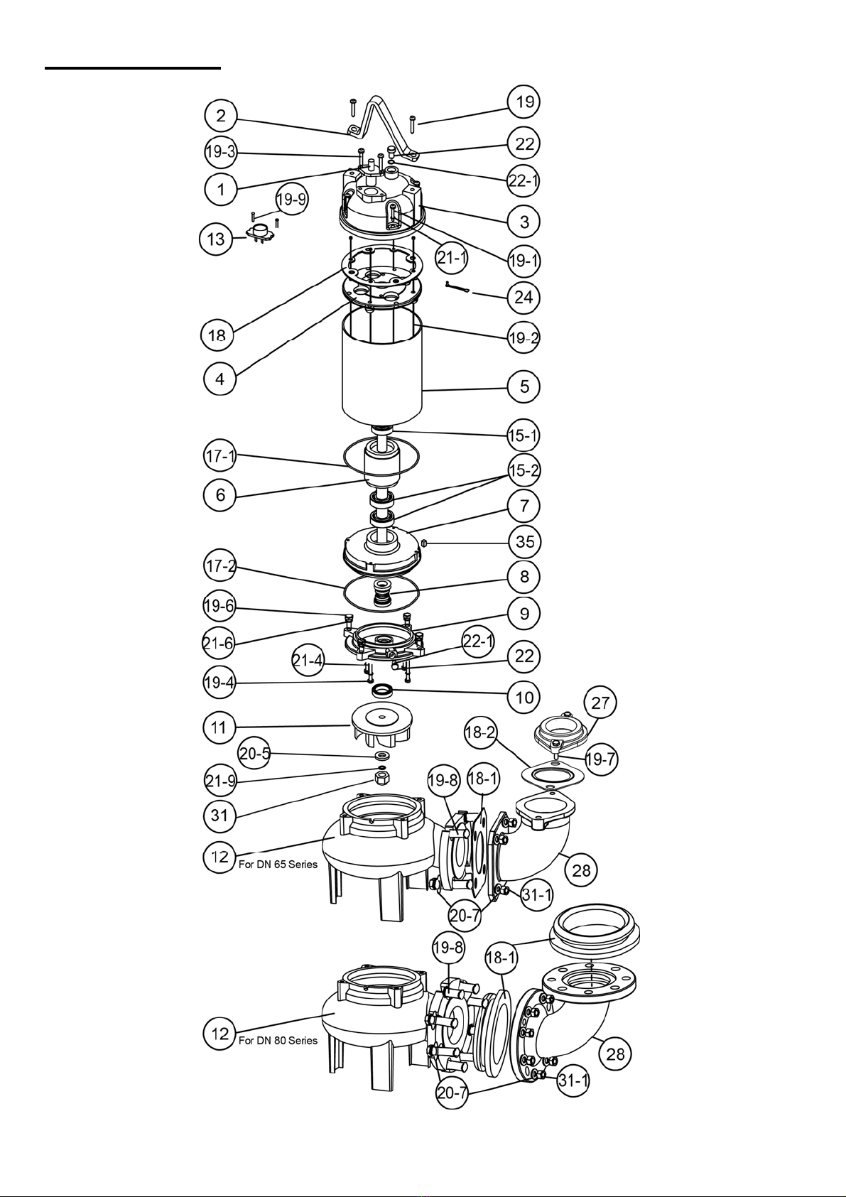
Construction
HIPPO DN 1.5~2HP

7
NO Part Material Photo NO Part Material Photo
2 Handle ASTM A36 12 Pump Casing
(DN65) EN-GJL-200
3 Motor
Cover EN-GJL-200 12 Pump Casing
(DN80) EN-GJL-200
4 Bracket EN-GJL-200 15-1
15-2 Upper Bearing
Lower Bearing NTN/TPI
5 Motor Housing
+Stator AISI 304
17-1
17-2 O-rings NBR
6 Shaft with Rotor AISI 410 18 Gasket NBR
7 Oil Chamber EN-GJL-200
18-1 Elbow Gasket
(DN65) NBR
8 Mechanical Seal CA/CE
+
SIC/SIC 18-1 Elbow Gasket
(DN80) NBR
9 Seal Housing EN-GJL-200 18-2 Flange Packing NBR
10 Lip Seal NBR
27 Flange
(DN65) EN-GJL-200
11 Impeller EN-GJL-200
28 Elbow EN-GJL-200
NO Part Material NO Part Material
19-2 Long Screw of motor Steel 21-9 Spring Washer AISI 304
19-3 Screw AISI 304 22 Oil Filler Plug AISI 304
19-4 Screw AISI 304 22-1 O-ring of Oil Filler Plug NBR
19-6 Screw AISI 304 24 Wire and Screw AISI 304
19-7 Screw AISI 304 31 Nut of impeller AISI 304
19-8 Screw AISI 304 31-1 Nut of Elbow AISI 304
19-9 Screw AISI 304 35 Key AISI 304
1 Cable H07RN-F/
SJTOW/STOW 20-5 Washer AISI 304
19-1 Screw AISI 304 21-6 Spring Washer AISI 304
14 Capacitor (1 Phase) - 21-1 Spring Washer AISI 304
13 Protector (3 Phase) KLIXON 20-7 Washer AISI 304
19 Screw AISI 304 21-4 Washer with O-ring AISI 304+NBR
TPI is a family brand of NTN group.

8
Construction
HIPPO DN 3HP

9
NO Part Material Photo NO Part Material Photo
2 Handle ASTM A36 12 Pump Casing
(DN65) EN-GJL-200
3 Motor
Cover EN-GJL-200 12 Pump Casing
(DN80) EN-GJL-200
4 Bracket EN-GJL-200 15-1
15-2 Upper Bearing
Lower Bearing NTN/TPI
5 Motor Housing
+Stator AISI 304
17-1
17-2 O-rings NBR
6 Shaft with Rotor AISI 410 18 Gasket NBR
7 Oil Chamber EN-GJL-200
18-1 Elbow Gasket
(DN65) NBR
8 Mechanical Seal CA/CE
+
SIC/SIC 18-1 Elbow Gasket
(DN80) NBR
9 Seal Housing EN-GJL-200 18-2 Flange Packing NBR
10 Lip Seal NBR
27 Flange
(DN65) EN-GJL-200
11 Impeller EN-GJL-200
28 Elbow EN-GJL-200
NO Part Material NO Part Material
19-2 Long Screw of motor Steel 21-9 Spring Washer AISI 304
19-3 Screw AISI 304 22 Oil Filler Plug AISI 304
19-4 Screw AISI 304 22-1 O-ring of Oil Filler Plug NBR
19-6 Screw AISI 304 24 Wire and Screw AISI 304
19-7 Screw AISI 304 31 Nut of impeller AISI 304
19-8 Screw AISI 304 31-1 Nut of Elbow AISI 304
19-9 Screw AISI 304 35 Key AISI 304
1 Cable H07RN-F/
SJTOW/STOW 20-5 Washer AISI 304
19-1 Screw AISI 304 21-6 Spring Washer AISI 304
14 Capacitor (1 Phase) - 21-1 Spring Washer AISI 304
13 Protector (3 Phase) KLIXON 20-7 Washer AISI 304
19 Screw AISI 304 21-4 Washer with O-ring AISI 304+NBR
TPI is a family brand of NTN group.
10
Construction
HIPPO DN 4~5.5HP

11
NO Part Material Photo NO Part Material Photo
2 Handle ASTM
A36 12 Pump Casing
(DN65) EN-GJL-200
3 Motor
Cover EN-GJL-200 12 Pump Casing
(DN80) EN-GJL-200
4 Bracket EN-GJL-200 15-1
15-2 Upper Bearing
Lower Bearing NTN/TPI
5 Motor Housing
+Stator AISI 304 17-1
17-2 O-rings NBR
6 Shaft with Rotor AISI 410 18 Gasket NBR
7 Oil
Chamber EN-GJL-200 18-1 Elbow Gasket
(DN65) NBR
8 Mechanical Seal CA/CE
+
SIC/SIC 18-1 Elbow Gasket
(DN80) NBR
9 Seal Housing EN-GJL-200 18-2 Flange Packing NBR
10 Lip Seal NBR 27 Flange
(DN65) EN-GJL-200
11 Impeller EN-GJL-200 28 Elbow EN-GJL-200
NO Part Material NO Part Material
19-3 Screw AISI 304 22 Oil Filler Plug AISI 304
19-4 Screw AISI 304 22-1 O-ring of Oil Filler Plug NBR
19-6 Screw AISI 304 24 Wire and Screw AISI 304
19-7 Screw AISI 304 31 Nut of impeller AISI 304
19-8 Screw AISI 304 31-1 Nut of Elbow AISI 304
19-9 Screw AISI 304 35 Key AISI 304
20-5 Washer AISI 304
1 Cable H07RN-F/
SJTOW/STOW 20-7 Washer AISI 304
19-2 Long Screw of motor Steel 21-9 Spring Washer AISI 304
19 Screw AISI 304 21-4 Washer with O-ring AISI 304+NBR
13 Protector (3 Phase) KLIXON 21-1 Spring Washer AISI 304
19-1 Screw AISI 304 21-6 Spring Washer AISI 304
TPI is a family brand of NTN group.

12
Disassembly and Assembly
1. Disassembly-
When disassembling pump, have a piece of cardboard or wooden board ready to
place the different parts on as you work. Do not pile parts on top of each other. They
should be laid out neatly in rows. The “O” ring and gasket cannot be used again
once they are removed. Have replacement parts ready. Disassemble in the following
order, referring to the sectional view.
Be sure to cut off power source before disassembly.
(1) Remove pump casing bolts, raise the motor section and remove pump casing.
(2) Remove shaft head bolt and impeller.
(3) Remove oil filler plug and drain lubricating oil.
(4) Remove intermediate casing bolts and oil chamber.
(Remember that any lubricating oil remaining in the mechanical seal chamber
will flow out.)
(5) Carefully remove mechanical seal, beware of not to scratch sliding surface of
motor shaft.
2. Assembly-
Re-assemble in reverse order of disassembly.
Be careful of the following points.
(a) During re-assembly, rotate the impeller by hand and check for smooth rotation.
If rotation is not smooth, perform steps-(3) through -(5) again.
(b) Upon completion of re-assembly step -(1) rotate the impeller by hand from the
suction inlet and check that it rotates smoothly without touching the suction cov-
er before operating the pump.
Please order “O” rings, packing, shaft seals and other parts from your dealer.

13
Nameplate format

14
Troubleshooting
Trouble Cause Remedy
Does not start.
Starts, but imme-
diately stops.
(1) Power failure (1)~(3) Contact electric power company and
devise counter-measures
(2) Large discrepancy between power source and
voltage
(3) Significant drop in voltage
(4) Motor phase malfunction (4) Inspect electric circuit
(5) Electric circuit connection faulty (5) Correct wiring
(6) Faulty connection of control circuit (6) Inspect connections and magnetic coil
(7) Fuses is blown (7) Check circuit then replace fuse
(8) Faulty magnetic switch (8) Replace with correct one
(9) Water is not at level indicated by Float (9) Raise water level
(10) Float is not in appropriate level (10) Adjust the position of float
(11) Float is not effective (11) Repair or replace
(12) Short circuit breaker is functioning (12) Repair location of short circuit
(13) Foreign matter clogging pump (13) Remove foreign matter
(14) Motor burned out (14) Repair or replace
(15) Motor bearing broken (15) Repair or replace
Operates, but
stops after a
while.
(1) Prolonged dry operation has activated motor pro-
tector and caused pump to stop (1) Raise water level to C.W.L
(2) High liquid temperature has activated motor pro-
tector and caused pump to stop (2) Lower liquid temperature
(3) Reverse rotation ! WARNING : (3) Correct rotation
Does not pump.
Inadequate vol-
ume.
(1) Reverse rotation (1) Correct rotation (see Operation)
(2) Significant drop in voltage (2) Contact electric power company
(3) Operating a 60Hz pump with 50Hz (3) Check nameplate
(4) Discharge head is high (4) Recalculate and adjust
(5) Large piping loss (5) Recalculate and adjust
(6) Low operating water level causes air suction (6) Raise water level or lower pump
(7) Leaking from discharge piping (7) Inspect, repair
(8) Clogging of discharge piping (8) Remove foreign matter
(9) Foreign matter in suction inlet (9) Remove foreign matter
(10) Foreign matter clogging pump (10) Remove foreign matter
(11) Worn impeller (11) Replace impeller
Over current (1) Unbalanced current and voltage (1) Contact electric power company
(2) Significant voltage drop (2) Contact electric power company and de-
vise counter-measure
(3) Motor phase malfunction (3) Inspect connections and magnetic switch
(4) Operating 50Hz pump on 60Hz (4) Check nameplate
(5) Reverse rotation ! WARNING : (5) Correct rotation
(6) Low head. Excessive volume of water (6) Replace pump with high head pump
(7) Foreign matter clogging pump (7) Remove foreign matter
(8) Motor bearing is worn out or damaged (8) Replace bearing
Pump vibrates;
excessive oper-
ating noise.
(1) Reverse rotation (1) Correct rotation
(2) Pump clogged with foreign matter
(2) Disassemble and remove foreign matter
(3) Piping resonates (3) Improve piping
(4) Strainer is closed too far (4) Open strainer

15
Note

16
Vol.PMHIPPODN-20051
Unit 1, 1 Wimbledon Avenue, Brandon, Suffolk, IP27 0NZ
01842 819130
This manual suits for next models
50
Table of contents
Popular Water Pump manuals by other brands


Makita
Makita EW1050H instruction manual

STIEBEL ELTRON
STIEBEL ELTRON PK 10 Operation and installation

Banjo
Banjo 300PI8PRO instruction manual

Flint & Walling
Flint & Walling 3CEH installation instructions

Federal Pump
Federal Pump BGP Series Installation, operation & maintenance manual

3P PRINZ
3P PRINZ Pompe 3P M Series Instruction & maintenance manual

MYERS
MYERS VRS10A-11 Installation and service manual

EasyPro
EasyPro EXP3200 Installation and service manual

Northern Industrial Tools
Northern Industrial Tools 1/2 HP SUMP PUMP owner's manual

Graco
Graco 257100 Operation

Grundfos
Grundfos Magna 32-120 Service instructions

Ozito
Ozito PSDW-350 instruction manual