IWILL KD266 User manual

1
KD266 Version 1.1AFB11325000000
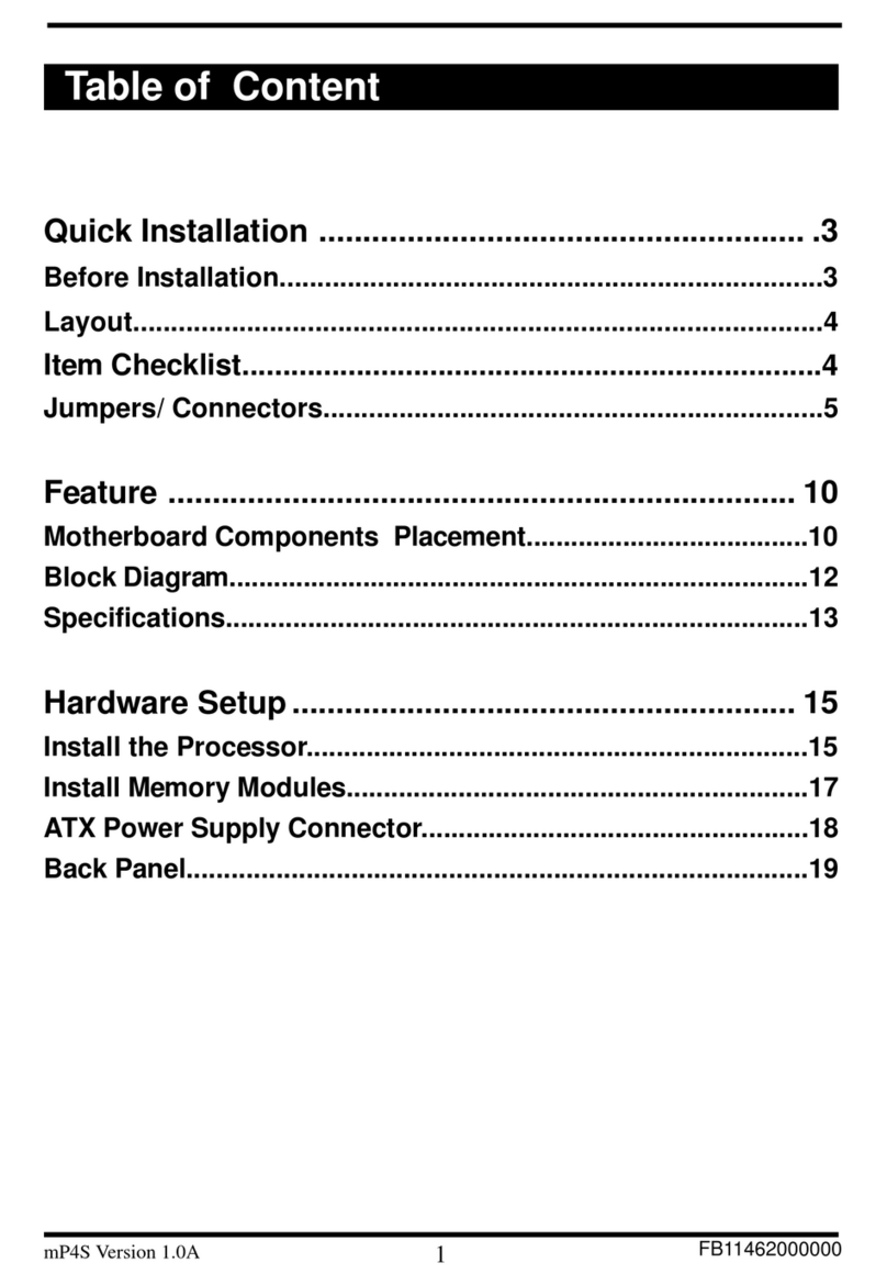
TableofContent
Quick Installation .................................................. 3
BeforeInstallation
Layout
ItemChecklist
Jumpers/Connectors
FormFactor
Feature.................................................................. 10
BlockDiagram
Specifications
HardwareSetup................................................... 13
Install theProcessor
Install MemoryModules
Back Panel

Chapter1QuickInstallation
2
BIOSSetup ........................................................... 17
BIOSSetup
MainMenu
StandardCMOSFeatures
AdvancedBIOSFeatures
AdvancedChipsetFeatures
IntegratedPeripherals
PowerManagementSetup
PnP/PCIConfigurations
PCHealthStatus
Iwill SmartSetting
LoadFail SafeDefaults
LoadOptimizedDefaults
SetSupervisor/UserPasswordSetting
Save&ExitSetup
ExitWithoutSaving

3
Chapter1QuickInstallation
Forinstallation,you may need someorall ofthe following tools:
Mediumsize flatblade screwdriver
Mediumsize Phillips head screwdriver
A3/16 inch nutdriverorwrench
Users must follow these guidelines to ensure the
motherboard is protected during installation.
1.Make sure your computer is powered-off whenever
working in with inside components
2.The motherboard, like all other electronic equipment, is
ensitive to static. Please take the proper precautions when
handling it. If possible, ground yourself by touching a metal
table or desk. keep the board in its conductive wrapping
until it is configured and ready to be installed in your
system.
3.Keep all magnets away from both your hard and floppy
disk drives, especially magnetic screwdrivers. Keep both
floppy and hard disks apart if disassembled.
4.Keep water and liquids away from your computer and its
components.
QuickInstallation
BeforeInstallation

Chapter1QuickInstallation
4
Layout
ItemChecklist
Themotherboard
Operationmanual
ATA/66/100cable
Floppy cable
PowerInstallerCD
Optional
USB riserkit
ThermalSensorforSystem
Infraredportcable
Faux
IR
PWR
USB
Com1
Com2
Mouse
p
a
r
a
l
l
e
l
Keyboar
d
USB
PS2_ SB
PCI5
PCI4
PCI3
PCI2
PCI1
CMOS
CPU Socket
Fcpu
Fcpu
F
r
o
n
t
P
a
n
e
l
C
o
n
n
e
c
t
o
r
USB
PCI6
F
D
C
I
D
E
0
VIO
IDE1
D
M
1
D
M
2
D
M
3
Socket462
ALi
M1535D+
ALi
Mdm WOL
Tsys
Fsys
KD266
AGP

5
Chapter1QuickInstallation
System temp
Clear CMOS
DRAM Voltage (VIO)
PS2_SB(JP6)
Normal(Default)
Enabled (Default) Disabled
1 2 31 2 3
1
1
2
1
2
2
3
3
ClearCMOS
Normal (Default)
1
2
3
Increase 5%
1
2
3
Increase 10%
1
2
3
System fan
CPU fan
Auxiliary fan
PINAssignment
1:GND
2:12V
3:Sense
1 2 3
Jumpers/Connectors

Chapter1QuickInstallation
6
Wake On LAN
Wake On Modem
PINAssignment
1:5VSB
2:GND
3:LAN_Wake
123
PINAssignment
1:5VSB
2:GND
3:ControlPin
123
Infrared connector(IR)
PINAssignment
1:VCC
2:FIR
3:IRRX
4:GND
5:IRTX
6:OVCROFF
1
2
3
4
5
6

7
Chapter1QuickInstallation
PIN NO Definition PIN NO Definition
1+3.3v 11 +3.3V
2+3.3v 12 -12V
3GROUND 13 GROUND
4+5V 14 Power Supply On
5GROUND 15 GROUND
6+5V 16 GROUND
7GROUND 17 GROUND
8Power Good 18 -5V
9+5V Standby 19 +5V
10 +12V 20 +5V
ATX power connector
1
10
11
20

Chapter1QuickInstallation
8
Front panel connector
1
12
24
Function PIN NO. Definition
PWR_ON(Power/Soft_off) 1,13
ALED(IDE LED) 7,8 PIN 7:Anode
PIN 8:Cathode
RST(RESET) 11,12 PIN 11:RST
PIN 12:GND
PLED(System Power LED) 15,16,17 PIN 15:VCC
PIN 16:NC
PIN 17:GND
SPKR(Speaker) 21,22,23,24
PIN 21:VCC
PIN 22:NC
PIN 23:NC
PIN 24:SPEAK(BUZZ)

9
Chapter1QuickInstallation
PIN
S
o
c
k
e
t
4
6
2
FormFactor
Socket462
ALi
M1535D+
ALi
KD266
3
0
5
m
m
193mm

10
Chapter2Feature
Feature
BlockDiagram
ALi M 1535D+
Sock 462 CPU
Keyboard/Mouse
Floppy
Parallel
Serial
Game Port
ALi M 1649
North Bridge
SDRAM
PCI Bus
AGP 4X/2X
Memory Bus
LPC
Ultra DMA/66/100
Clock
Generator
PCI x 6

11
Chapter2Feature
Specifications
Processor/(SocketA)
Supports1processorSocketA
Supports100MHz/133MHz(FrontSide Bus)
SupportsAMDAthlon andDuron CPU
CPU Frequency/VoltageSelection
SupportsVcoreselection byBIOS(1.125Vto1.85VStep 0.025V)
SupportsVIOselection byJumper(5%or10%)
SupportsCPUMultiplierselection byBIOS(5Xto15XStep 0.5X)
SupportsCPUExternalFrequencyselection byBIOS(100MHz-180MHz
Step/MHz)
Memory
SupportsPC100/PC133 SDRAM
Supports16M/64M/128M/256Mbit512DRAM technology
Supportsup to3GBDRAM
Graphics
SupportsAGP2X/AGP4XUniversalSlot
GeneralI/O
PCI2.2compliance
Supports32-bit/33MHzPCIinterface
SupportsATA33/66/100 IDEinterface
SupportsFloppyinterface
Supports16550AUARTinterface
SupportsECP/EPP interface
SupportsPS2interface
SupportsSIR/CIR/MIRinterface
SupportsUSB interface
ChipSet
ALiM1649,BGA528
ALiM1535D+,BGA352

12
Chapter2Feature
Management
Supportsvoltage monitoring (+12V/+5V/Vcore/+3.3V)
Supportsfan controlsignal(CPU/SYS)
Supportstemperaturesensor(CPU/SYS)
SupportsPoweron byExt.Modem/Int.Modem/RTC/PME
SupportsResumebyLAN/Ext.Modem/Int.Modem/PS2Keyboard/PS2
SupportsACPI
SupportsAPM/DMI/SMBUS/PnP
SupportsBIOSROM Flash Control
SupportsManuallyAssign PCIIRQ
Expansion Slot,Socketsand Connectors
One Socket462 socket
ThreeDIMM sockets
One UniversalAGPslot
Six32bit/33MHzBus MasterPCIslots
TwoIDEconnectors
One FDC connector
One ExternalUSBx2 connectors
Others
ATXFormFactor305mmx193mm

13
Chapter3HardwareSetup
LocatetheZIFsocketandopen it
by firstpulling the leverofsocket
upward.
Step1:Step2:
Insertthe CPUintothe socket.
Please keep the leverrightangle
when inserting CPU.
Step3:Step4:
When inserting the CPUPlease
notethe correctorientation as
shown.The notched corner
shouldpointtowardthe end of
the lever.
Push theleverdowntoclose the
socket.
HardwareSetup
Install theProcessor
The CPU should have a fan attached it to prevent
overheating.
Be sure that there is sufficient air circulation across the
processors heatsink by regularly checking that your CPU fan
isworking. Withoutsufficient circulation, theprocessor could
overheat and damage both the processor and the
motherboard. You may install an auxiliary fan, if necessary.

14
Chapter3HardwareSetup
Push the clipofheatsink
downwardtohockthe earof
socketfirmly.
Step7:
Don't forget to set the correct Bus Frequency and
Multiple(frequency multiple setting is available only
on unlocked processors) for your Socket 370
processor or else boot-up may not be possible.
Finally,attach the fan cabletothe
CPUfan headerFCPU.
Step6:
Step5:
Attach the heatsinktothe CPU.
Be careful not to scrape the motherboard when
mounting a clampstyle processor fan or else damage
may occur to the motherboard.

15
Chapter3HardwareSetup
Insertthe RAM moduleintotheDIMM
socket. Press the latches intothe notches ofthe
RAM module.
Install MemoryModule
The motherboardhas three memorysocketsand supportsmemorysize
up to3GB.
Open latches ofDIMM socket.Proofread the RAM moduletothe
DIMM Socket.
Step3:Step4:
Step1:Step2:

16
Chapter3HardwareSetup
Back Panel
Function color Description
PS2/Mouse Green This connector can be used to support a
PS/2 mouse.
PS2/keyboard Purple This connector can be used to support a
PS/2 keyboard.
Universal Serial
Bus Black This motherboard has two USB ports, any
USB-compatible peripherals and/or hub
can be connected into either USB port.
Serial port Teal One serial port is ready for a modem or
other serial devices.
Parallel port Burgundy This connector is used for printers, or
other parallel devices.

17
Chapter4BIOSSetup
BIOSSetup
BIOSSetup
UpgradeBIOS
The BIOScan be upgraded fromadiskettewiththe AwardFlash utility
— AWDFLASH.EXE.The BIOSimage file,and updateutilityare
availablefromIWILL’sWEBsite:support.iwill.net
If you haveany problem, pleasecontact withus inIWILL’s web
site:www.iwill.net
EnterBIOSsetup program
Power-on the systembyeitherpressing the Power-Onbutton,or
byusing anyofthe power-on features provided bythe
motherboard.Then,press the <Del>keyafterthe Power-OnSelf
Test(POST),and beforethe scanning ofIDEdevices.Simply
lookforthe message “PressDEL toenterSETUP”displayed at
the bottomofthe screen during the bootup process.Ifthe
message disappearsbeforeyou’ve had achance torespond,
you can restartthe systembyturning offthe systempowerthen
turniton again,orpressing the “RESET”button on the system
case,orpressing <Ctrl>,<Alt>and <Del>keys simultaneously.
Generally, the BIOS default settings have been carefully
chosen by IWILL's Engineers provide the absolute
maximum performance and reliability. It is very
dangerous to change any setting without full
understanding. We strongly recommend that you.
DO NOT update BIOS if the system works perfectly.
DO NOT change any setting unless you fully
understand what it means.

18
Chapter4BIOSSetup
Ifthe systemisno longerabletobootafterchanging thesettings,the only
waytoclearthe datastored inRTCCMOS.To resettheRTCCMOSdata,
takethe JP1 jumpercap offpins 1-2,place ontopins 2-3,and then place
backontopins 1-2again.itreturns the RTCtothe defaultsetting.Then,
getintothe BIOSsetup program,choose Load Fail-SafeDefaults;Load
OptimizedDefaults,andselectIWILL’sEngineerstosetdefaultsettings in
yourCMOS.
Using BIOSsetup program
Up Move to the previous field
Down Move to the next field
Left Move to the field on the left hand side
Right Move to the field on the right hand side
<Esc> Quit from setup program without saving changes,
ro Exit from current menu page and return to
main menu page
<PgUp>or<+> Select the previous value for a field.
<PgDn>or<-> Select the next value for a field
<F1> General Help
<F2> Item Help
<F5> Previous Values
<F6> Fail-Safe Defaults
<F7> Optimized Deaults
<F10> Save the current value and exit setup program

19
Chapter4BIOSSetup
MainMenu
The mainmenu allowsyou toselectfromseveralsetup items.Use the
arrowkeys toselectamong these itemsand press <Enter>keytoenter
the sub-menu.Abriefdescription ofeach highlighted selection appears
on the bottomofthe screen.
CMOS Setup Utility-Copyright(c) 1984-2001 Award Software
Standard CMOS Features
Advanced BIOS Features
Advanced Chipset Features
Integrated Peripherals
Power Management Setup
PnP/PCI Configurations
PC Health Status
ESC: Quit
F10: Save & Exit Setup
Time, Date Hard Disk Type...
IWILL Smart Setting
Load Fail-Safe Defaults
Load Optimized Defaults
Set Supervisor Password
Set User Password
Save & Exit Setup
Exit Without Saving
: Select Item

20
Chapter4BIOSSetup
StandardCMOSFeatures
CMOS Setup Utility-Copyright(c) 1984-2001 Award Software
Standard CMOS Features
Date (mm:dd:yy)
Time (hh:mm:ss)
IDE Primary Master
IDE Primary Slave
IDE Secondary Master
IDE Secondary Slave
DriveA
DriveB
Floppy 3 Mode Support
Video
Halt On
Base Memory
Extended Memory
Total Memory
Fri, Jan 5 2001
15:17:48
[None]
None]
None]
None]
1.44M,3.5i n.]
[None]
[Disabled]
EGA/VGA]
All Errors]
640k
31744k
32768k
[
[
[
[
[
[
Item Help
Menu Level
Change the day, month,
year and century
Date
Thisfieldspecifies the currentdate.The dateformatis<day>,
<month>,<day>,and <year>.
Time
Thisfieldspecifies the currenttime.The timeformatis<hour>,
<minute>,and <second>.The timeiscalculated based on the
24-hour(military-time)clock.
IDEPrimaryMaster/PrimarySlave/SecondaryMaster
/SecondarySlave
Press “Enter”toenternextpage fordetail harddrive setting.
IDEHDDAuto-Detection
Auto-Detectthe HDDsCapacity,and itsparameters,ex:Cylinder,
Head and Sector.
Table of contents
Other IWILL Motherboard manuals

IWILL
IWILL P4GB Series User manual

IWILL
IWILL DN800 User manual

IWILL
IWILL FB24624100 User manual

IWILL
IWILL mp4s Original operating instructions
IWILL
IWILL P55TV User manual

IWILL
IWILL DVD266 User manual

IWILL
IWILL DK8X User manual

IWILL
IWILL KK266 User manual

IWILL
IWILL KK400 Series User manual
IWILL
IWILL K7S3 Series User manual