Evco EV3 Mix User manual

144XXXME4.00 - 06/2020
EV3 Mix
Inverter and keypad for food mixers
User manual

144XXXME4.00 - 06/2020 - EV3 Mix | 2
CONTENTS
IMPORTANT INFORMATION 4
IMPORTANT SAFETY INFORMATION 5
SAFETY INFORMATION RELATING TO THE PRODUCT 6
CHAPTER 1. INTRODUCTION 8
1.1 Compliance 8
CHAPTER 2. TECHNICAL DATA 9
2.1 Technical specications 9
2.1.1 Other technical information - Inverter 9
2.2 Technical specications - Basic/Plus interfaces 9
2.2.1 Other technical information - Basic/Plus interfaces 9
CHAPTER 3. MECHANICAL ASSEMBLY 10
3.1 Installation - Inverter 10
3.1.1 Dimensions - Inverter 11
3.1.2 Minimum installation distances 11
3.2 Installation - Basic/Plus Interfaces 13
3.2.1 Dimensions - Basic/Plus Interfaces 13
CHAPTER 4. ELECTRICAL CONNECTIONS 14
4.1 Connection best practice 14
4.1.1 Wiring guidelines 15
4.2 Wiring diagram - Inverter 16
4.2.1 Earthing 17
4.3 Wiring diagram - Basic/Plus Interface 17
4.4 Inverter / Interface connection 18
CHAPTER 5. USER INTERFACE 19
5.1 Touch keys 19
5.2 Icons 19
5.2.1 Basic Interface 19
5.2.2 Plus Interface 20
5.3 Functions menu 20
5.3.1 Select/start manual cycle 20
5.3.2 Automatic select/start cycle with several stages 22
5.3.3 Reverse function 24
5.3.4 Edit Parameters 25
CHAPTER 6. OPERATION 26
6.1 Setting the speed 26
6.1.1 Basic Interface 26
6.1.2 Plus Interface 27
6.2 LED 27

| 4
144XXXME4.00 - 06/2020 - EV3 Mix
IMPORTANT INFORMATION
Liability and residual risks
EVCO assumes no liability for any damage caused by the following (by way of example; this is not an exhaustive list):
• Installation/useforpurposesotherthanthosespeciedand,inparticular,notadheringtothesafetyprovisionssetout
by current regulations in the country in which the product is installed and/or contained in this manual;
• Useinappliancesthatdonotguaranteesufcientprotectionagainstelectricshocks,wateranddustwithinthe
installation conditions created;
• Useinappliancesthatallowaccesstohazardouspartswithouttheuseofakeyedortooledlockingmechanismwhen
accessing the instrument;
• Tampering and/or modifying the product;
• Installation/use in appliances which do not comply with current regulations in the country in which the product is installed.
The customer/manufacturer is responsible for ensuring their machine complies with these regulations.
EVCO’s responsibility is limited to the correct and professional use of the product in accordance with regulations and the
instructions contained in this manual and other product support documents.
TocomplywithEMCstandards,observealltheelectricalconnectioninstructions.Asitdependsonthewiringconfigurationas
wellastheloadandtheinstallationtype,compliancemustbeverifiedforthefinalmachineasspecifiedbytherelevantproduct
standard.
Disclaimer
This document is the exclusive property of EVCO. It contains a general description and/or a description of the technical
specifications for the services offered by the products listed herein. This document should not be used to determine the
suitability or reliability of these products in relation to specific user applications. Each user or integration specialist should
conducttheirowncompleteandappropriateriskanalysis,inadditiontocarryingoutaproductevaluationandtestinrelation
to its specific application or use. Users can send us comments and suggestions on how to improve or correct this publication.
Neither EVCO nor any of its associates or subsidiaries shall be held responsible or liable for improper use of the information
contained herein.
EVCOhasapolicyofcontinuousdevelopment.Therefore,EVCOreservestherighttomakechangesandimprovementstoany
product described in this document without prior notice.
The images in this document and other documentation supplied with the product are provided for illustrative purposes only and
may differ from the product itself.
The technical data in this manual is subject to change without prior notice.
Terms and Conditions of use
Permitted use
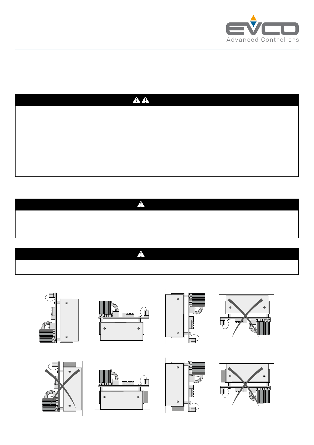
Thedevicemustbeinstalledandusedinaccordancewiththeinstructionsprovidedand,inparticular,hazardousliveparts
must not be accessible under normal conditions.
The device must be suitably protected from water and dust with regard to its application and must also only be accessible with
the aid of a tool (with the exception of the front panel).
Only qualified personnel may install the product or perform technical support procedures on it.
The customer must only use the product as described in the documentation relating to that product.
Prohibited use
Anyuseotherthanthosedescribedinthe"Permitted use"sectionandintheproductsupportdocumentationisprohibited.
The product must be installed outside hazardous ATEX areas.
Disposal
The device must be disposed of in accordance with local regulations regarding the collection of electrical and
electronic appliances.
Consider the environment
Withaviewtorespectingtheenvironment,westrivetoadheretotheenvironmentalperformanceofthecompany,
whiletakingaccountofcustomerrequirements,technologicalinnovationsintermsofmaterialsandtheexpectations
ofthecommunitytowhichwebelong.EVCOplacesgreatimportanceonrespectingtheenvironment,encouragingall
associatestobecomeinvolvedwithcompanyvaluesandguaranteeingsafe,healthyandfunctionalworkingconditions
andworkplaces.
Please consider the environment before printing this document.

| 5
144XXXME4.00 - 06/2020 - EV3 Mix
IMPORTANT SAFETY INFORMATION
Please read this document carefully before installation; study all the warnings before using the device. Only use the device in
accordance with the methods described in this document. The following safety messages may be repeated several times in
thedocument,toprovideinformationregardingpotentialhazardsortoattractattentiontoinformationwhichmaybeusefulin
explaining or clarifying a procedure.
Thissymbolisusedtoindicateariskofelectricshock.
Itisasafetyindicationandassuch,shouldbeobservedtoavoidpotentialaccidentsorfatalities.
Thissymbolisusedtoindicateariskofseriouspersonalinjury.
Itisasafetyindicationandassuch,shouldbeobservedtoavoidpotentialaccidentsorfatalities.
DANGER
DANGER indicatesasituationofimminentdangerwhich,ifnotavoided,will lead to death or serious injury.
WARNING
WARNING indicatesasituationofimminentdangerwhich,ifnotavoided,may lead to death or serious injury.
CAUTION
CAUTION indicatesapotentiallyhazardoussituationwhich,ifnotavoided,could cause minor or moderate injury.
NOTICE
NOTICE indicates a situation not related to physical injuries but which
,ifnotavoided,
could damage the equipment.
NOTE:Themaintenance,repair,installationanduseofelectricalequipmentmustonlybeentrustedtoqualifiedpersonnel.
QUALIFIED PERSONNEL
Only suitably trained and experienced personnel capable of understanding the content of this manual and all documentation
regardingtheproductareauthorisedtoworkonandwiththisequipment.Furthermore,thepersonnelmusthavecompleted
coursesinsafetyandmustbeabletorecogniseandpreventtheimplieddangers.Thepersonnelmusthavesuitabletraining,
knowledgeandexperienceatatechnicallevel,andbecapableofanticipatinganddetectingpotentialriskscausedbyusing
theproduct,aswellaschangingthesettingsandmodifyingthemechanical,electricandelectronicequipmentfortheentire
systeminwhichtheproductisused.Allpersonnelworkingonandwiththeproductmustbeentirelyfamiliarwiththerelevant
standardsanddirectives,aswellassafetyregulations.

| 6
144XXXME4.00 - 06/2020 - EV3 Mix
SAFETY INFORMATION RELATING TO THE PRODUCT
Beforecarryingoutanyworkontheequipment,readtheseinstructionscarefully,makingsureyouunderstandeverything.
DANGER
RISK OF ELECTRIC SHOCK, EXPLOSION OR ELECTRIC ARC
• Onlysuitablytrainedpersonnel,familiarwithandcapableofunderstandingthecontentofthemanualandallrelevant
documentation,areauthorisedtoworkonandwiththisinverter.Furthermore,thepersonnelmusthavecompletedcourses
insafetyandmustbeabletorecogniseandpreventtheimplieddangers.Installation,adjustmentandmaintenancemust
only be carried out by qualified personnel.
• Variousproductcomponents,includingtheprintedcircuits,runathazardousvoltagelevels.
• Only use electrically insulated and suitably calibrated measuring devices and equipment.
• Do not handle the equipment while the power supply is connected.
• Do not touch the unshielded components or the terminals while they are live.
• Themotorsmaygeneratevoltageiftheshaftisrotated.Beforecarryingoutanyworkontheinverter,lockthemotorshaft
to prevent it from rotating.
• Beforeworkingontheinverter:
• Disconnect the power supply.
• UseasuitablycalibratedandelectricallyinsulatedVoltmetertomakesurethepowersupplyisdisconnected.
• Waitfor5minutedafterdisconnectingthepowersupplybeforeinstalling/uninstallingaccessories,hardware,cablesor
wires,toallowthecondenserstodischargeanyresidualvoltage.
• Donotopen,disassemble,repairormodifytheproduct.
• Beforehandlingtheproduct,makesureyouarewearingallthenecessarypersonalprotectiveequipment(PPE).
• Do not expose the equipment to liquids or chemicals.
• Before applying voltage to the inverter:
• Makesuretherunningperiodhasbeencompletedandnopartsofthesystemcanbecomehazardous.
• Ifthemainspowersupplyterminalsandthemotoroutputterminalshavebeenearthedandcircuited,removetheearth
and short circuits on these terminals.
• Makesurealltheequipmentisproperlyearthed.
• Makesureallprotectiveelements,suchascovers,hatchesandgrilles,arefittedand/orclosed.
• Checkallwiringconnections.
DANGER
RISK OF ELECTRIC SHOCK AND FIRE
• Do not use the device with loads greater than those indicated in the technical data section.
• Do not exceed the temperature and humidity ranges indicated in the technical data section.
• Usetherequiredsafetyinterlocks(fusesand/ormagnetothermalswitches)ofasuitablesizebetweenthepowersupplyand
the inverter.
DANGER
RISK OF ELECTRIC SHOCK OR MALFUNCTIONING OF THE EQUIPMENT
Do not use damaged products or accessories.
Thisdevicewasdesignedtooperateinnon-hazardousenvironments,excludingapplicationsthatgenerate,orcouldpotentially
generate,hazardousatmospheres.Onlyinstallthisdeviceinareasandforapplicationswhicharereliablyfreefromhazardous
atmospheres.
DANGER
RISK OF EXPLOSION
• Onlyinstallandusethisdeviceinsitesthatarenotatrisk.
• Donotinstallorusethisdeviceinapplicationswhicharecapableofgeneratinghazardousatmospheres,suchas
applications that use flammable refrigerants.

| 7
144XXXME4.00 - 06/2020 - EV3 Mix
The EV3 Mix must be installed in a suitably ventilated environment to allow heat to dissipate.
Thetemperatureofthedevicecanexceed80°C(176°F)duringoperation.
WARNING
HOT SURFACES
• Avoidallcontactwithhotsurfaces.
• Do not leave flammable or heat-sensitive components on or near hot surfaces.
• Makesuretheproducthascooledsufficientlybeforehandlingit.
• Makesuresufficientheatdissipationtakesplacebyperformingatestundermaximumloadconditions.
WARNING
MALFUNCTIONING OF THE EQUIPMENT
• Performthewiringcarefully,incompliancewithelectromagneticcompatibilityrequirements.
• Donotoperatetheproductwithunknownorincorrectsettingsordata.
• Carry out a full start-up test.
• Makesurethewiringiscorrectforthesettings.
• Use shielded cables for all I/O signal and communication cables.
• Use double-shielded cables for motor wiring.
• Minimisethelengthoftheconnectionsasmuchaspossible,toavoidwindingthecablesaroundelectricallyconnectedparts.
• The signal (communication and corresponding power supplies) and power cables for the device must be routed separately.
• Beforeapplyingthepowersupply,checkallthewiringconnections.

| 8
144XXXME4.00 - 06/2020 - EV3 Mix
EV3 Mixisacontrollerforindustrialfoodmixers,consistingofaninverterforasynchronousmotorsandauserinterface.
There are 2 types of interface:
• Basic:Youcanset3rotationspeeds(high,mediumandlow)andmixingcycleswithupto2stages.
Thereareseveralfunctions,suchas:
– Play/Pause;
– Reverse,toremovethedough/mixturefromthespiralattachment;
– Speed change during operation;
– Motor alarm display.
• Plus: You can set 10 rotation speeds and mixing cycles with up to 10 stages. The time for each stage may vary between
1and99minutesandcanbecustomised.Thereareseveralfunctions,suchas:
– Play/Pause;
– Reverse,toremovethedough/mixturefromthespiralattachment;
– Speed change during operation;
– Motor alarm display.
1.1 COMPLIANCE
2014/35/UE: Low voltage directive applied in accordance with standard EN61800-5-1 for electrical safety.
2014/30/UE: Electromagnetic compatibility directive applied in accordance with standard EN61800-3 class C2.
CHAPTER 1. INTRODUCTION

| 9
144XXXME4.00 - 06/2020 - EV3 Mix
2.1 TECHNICAL SPECIFICATIONS
Ambientoperatingconditions: -10...55°C(14...131°F)10…90%RHnon-condensing
Transportationandstorageconditions:-20...60°C(-4...140°F)10…90%RHnon-condensing
Altitude: Maximum1000m(3,280ft)
Pollution category: 2
Protection degree: IP00
Overvoltage category: II
Powersupply: 230Vac±10%50/60Hz
Input current (RMS): 0.75 kW:5A
1.5 kW:10A
2.2 kW:15A
Output current (RMS): 0.75 kW:3.3A
1.5 kW:6.3A
2.2 kW:8.8A
Cooling method: 0.75 kW models: Natural ventilation
Other models:Forcedventilation
2.1.1 Other technical information - Inverter
Input properties (SELV)
Digital Inputs: 3 digital inputs
Output properties
Digitaloutputs: 1relayoutput5Aat250Vac
MotorOutput: 0...230Vac,3phatVin=230Vac
Carrierfrequency: 5...16kHz
Nominaloverload: Maximum150%for60seconds
Outputfrequency: 0...100Hz
Serial communication port properties (SELV)
RS-485 serial port:
1opto-isolatedRS-485MODBUSRTUSlaveserialport,reinforcedforconnectionwithBasic/
Plus interface. Maximum baud rate: 38400 bps - Maximum cable length: 1.5 m (4.9 ft.)
Compliance
CE in accordance with directives EN61800-3 and EN61800-5-1 in C2 category
2.2 TECHNICAL SPECIFICATIONS - BASIC/PLUS INTERFACES
The product complies with the following harmonised standards: EN60730-1 and EN60730-2-9
Device construction: Incorporated device
Device purpose: Operating control device
Type of action: 1
Pollution category: 2
Overvoltage category: I
Nominal pulse voltage: 330 V
Powersupply: 12Vdc±10%
Consumption: 0.7 W
Ambientoperatingconditions: 0...55°C(32...131°F)10…90%RHnon-condensing)
Transportationandstorageconditions:-25...70°C(-13...158°F)10…90%RHnon-condensing
Softwareclass: A
Ambientfrontprotection: IP65
2.2.1 Other technical information - Basic/Plus interfaces
Serial communication port properties (SELV)
RS-485 serial port:
1 RS-485 MODBUS RTU Master Serial port
CHAPTER 2. TECHNICAL DATA

| 10
144XXXME4.00 - 06/2020 - EV3 Mix
CHAPTER 3. MECHANICAL ASSEMBLY
3.1 INSTALLATION - INVERTER
Inverterinstallationanticipatestheuseofacornerbracket(notsupplied).
Inparticular,thesafetyinstructions,electricalrequirementsandcurrentregulationsforthemachineortheprocessinwhich
this device is involved must be observed.
DANGER
RISK OF ELECTRIC SHOCK, EXPLOSION OR ELECTRIC ARC
• Beforehandlingtheproduct,makesureyouarewearingallthenecessarypersonalprotectiveequipment(PPE).
• Do not expose the equipment to liquids or chemicals.
• Before applying voltage to the inverter:
• Makesuretherunningperiodhasbeencompletedandnopartsofthesystemcanbecomehazardous.
• Ifthemainspowersupplyterminalsandthemotoroutputterminalshavebeenearthedandcircuited,removetheearth
and short circuits on these terminals.
• Makesurealltheequipmentisproperlyearthed.
• Makesureallprotectiveelements,suchascovers,hatchesandgrilles,arefittedand/orclosed.
• Checkallwiringconnections.
Thisdevicewasdesignedtooperateinnon-hazardousenvironments,excludingapplicationsthatgenerate,orcouldpotentially
generate,hazardousatmospheres.Onlyinstallthisdeviceinareasandforapplicationswhicharereliablyfreefromhazardous
atmospheres.
DANGER
RISK OF EXPLOSION
• Onlyinstallandusethisdeviceinsitesthatarenotatrisk.
• Donotinstallorusethisdeviceinapplicationswhicharecapableofgeneratinghazardousatmospheres,suchas
applications that use flammable refrigerants.
ForEV3 Mix 0.75 kW models:
DANGER
RISK OF EXPLOSION
Only install the equipment in a vertical position (condensers towards the bottom).
0.75 kW models
1.5 kW / 2.2 kW models
Fig. 1. EV3 Mix installation position

| 11
144XXXME4.00 - 06/2020 - EV3 Mix
3.1.1 Dimensions - Inverter
59 (2.32)
40 (1.57)
0.8 (0.03)
154 (6.06)
95 (3.74)
27 (1.06) 100 (3.94)
mm (in.)
Fig. 2. Inverter dimensions
3.1.2 Minimum installation distances
Install the EV3 Mix inverterobservingtheminimumdistanceof40mm(1.57in.)atthesides,soastoguaranteeadequate
ventilationandaerationofthesystem.Makesurethereisadistanceofatleast10mm(0.39in.)betweenthesupportbaseand
the cooler.
WARNING
HOT SURFACES
• Avoidallcontactwithhotsurfaces.
• Do not leave flammable or heat-sensitive components on or near hot surfaces.
• Makesuretheproducthascooledsufficientlybeforehandlingit.
• Makesuresufficientheatdissipationtakesplacebyperformingatestundermaximumloadconditions.
40 (1.57)
10 (0.39)
40 (1.57)
mm (in.)
Fig. 3. Minimum inverter installation distances - view from below

| 12
144XXXME4.00 - 06/2020 - EV3 Mix
40 (1.57)
mm (in.
)
40 (1.57)
40 (1.57) 40 (1.57)
Fig. 4. Minimum inverter installation distances - front view

| 13
144XXXME4.00 - 06/2020 - EV3 Mix
3.2 INSTALLATION - BASIC/PLUS INTERFACES
71
(
2.7
9)
29 (1.14)
mm (in.)
Fig. 5. Installing Basic/Plus interfaces
3.2.1 Dimensions - Basic/Plus Interfaces
33 (1.30)
75 (2.95)
69 (2.71)
59 (2.32)
mm (in.)
Fig. 6. Basic/Plus interface dimensions

| 14
144XXXME4.00 - 06/2020 - EV3 Mix
CHAPTER 4. ELECTRICAL CONNECTIONS
4.1 CONNECTION BEST PRACTICE
The following information describes the wiring guidelines and best practices which should be observed when using the inverter.
DANGER
RISK OF ELECTRIC SHOCK, EXPLOSION OR ELECTRIC ARC
• Onlysuitablytrainedpersonnel,familiarwithandcapableofunderstandingthecontentofthemanualandallrelevant
documentation,areauthorisedtoworkonandwiththisinverter.Furthermore,thepersonnelmusthavecompletedcourses
insafetyandmustbeabletorecogniseandpreventtheimplieddangers.Installation,adjustmentandmaintenancemust
only be carried out by qualified personnel.
• Variousproductcomponents,includingtheprintedcircuits,runathazardousvoltagelevels.
• Only use electrically insulated and suitably calibrated measuring devices and equipment.
• Do not touch the unshielded components or the terminals while they are live.
• Themotorsmaygeneratevoltageiftheshaftisrotated.Beforecarryingoutanyworkontheinverter,lockthemotorshaft
to prevent it from rotating.
• Beforeworkingontheinverter:
• Disconnect the power supply.
• UseasuitablycalibratedandelectricallyinsulatedVoltmetertomakesurethepowersupplyisdisconnected.
• Waitfor5minutesafterdisconnectingthepowersupplybeforeinstalling/uninstallingaccessories,hardware,cablesor
wires,toallowthecondenserstodischarge.
• Donotopen,disassemble,repairormodifytheproduct.
• Beforehandlingtheproduct,makesureyouarewearingallthenecessarypersonalprotectiveequipment(PPE).
• Do not expose the equipment to liquids or chemicals.
• Before applying voltage to the inverter:
• Makesuretherunningperiodhasbeencompletedandnopartsofthesystemcanbecomehazardous.
• Ifthemainspowersupplyterminalsandthemotoroutputterminalshavebeenearthedandcircuited,removetheearth
and short circuits on these terminals.
• Makesurealltheequipmentisproperlyearthed.
• Makesureallprotectiveelements,suchascovers,hatchesandgrilles,arefittedand/orclosed.
• Checkallwiringconnections.
DANGER
RISK OF ELECTRIC SHOCK AND FIRE
• Do not use the device with loads greater than those indicated in the technical data section.
• Do not exceed the temperature and humidity ranges indicated in the technical data section.
When the EV3 Mixisinstandbyandthemotorisnotrunning,thelatterremainslive.
DANGER
RISK OF ELECTRIC SHOCK
Do not handle the motor when the EV3 Mix is in standby.

| 15
144XXXME4.00 - 06/2020 - EV3 Mix
WARNING
MALFUNCTIONING OF THE EQUIPMENT
• Performthewiringcarefully,incompliancewithelectromagneticcompatibilityrequirements.
• Donotoperatetheproductwithunknownorincorrectsettingsordata.
• Carry out a full start-up test.
• Makesurethewiringiscorrectforthesettings.
• Use shielded cables for all I/O signal and communication cables.
• Use shielded cables for motor wiring.
• Minimisethelengthoftheconnectionsasmuchaspossible,toavoidwindingthecablesaroundelectricallyconnectedparts.
• The signal (communication and corresponding power supplies) and power cables for the device must be routed separately.
• Beforeapplyingthepowersupply,checkallthewiringconnections.
4.1.1 Wiring guidelines
Whenwiringthecontrollers,observethefollowingstandards:
• TheI/Oandcommunicationwiringmustbekeptseparatefromthepowersupplywiring.Thesetwotypesofwiringmust
be routed in separate ducts.
• Makesuretheoperatingenvironmentandconditionsfallwithinthespeciedvalues.
• Usewireswiththecorrectdiameter,suitedtothevoltageandcurrentrequirements.
• Use copper conductors (compulsory).
• Use shielded twisted pair cables for analogue/digital I/O connections.
• UseshieldedtwistedpaircablesfornetworkandRS-485serialconnections.
Use correctly earthed shielded cables for all inputs or analogue outputs and for communication connections.
WARNING
MALFUNCTIONING OF THE EQUIPMENT
• Performthewiringcarefully,incompliancewithelectromagneticcompatibilityrequirements.
• Donotoperatetheproductwithunknownorincorrectsettingsordata.
• Carry out a full start-up test.
• Makesurethewiringiscorrectforthesettings.
• Use shielded cables for all I/O and communication signals.
• Use shielded cables for motor wiring.
• Minimisethelengthoftheconnectionsasmuchaspossible,toavoidwindingthecablesaroundelectricallyconnectedparts.
• Thesignal(digitalinputs,communicationandcorrespondingpowersupplies)andpowercablesfor the device must be
routed separately.
• Beforeapplyingthepowersupply,checkallthewiringconnections.

| 16
144XXXME4.00 - 06/2020 - EV3 Mix
4.2 WIRING DIAGRAM - INVERTER
Compact
Ingresso
Alimentazione
Uscita Motore
+ Vdc-GND
UVWPE
COM NC CNO
LNPE
ID 2ID 2ID1
RS-485 Ingressi
digitali
N.C. Uscita
digitale
TERMINALS
LPHASE-Powersupplyinput
NNEUTRAL-Powersupplyinput
PE EARTH-Powersupplyinput(*)
RS-485 RS-485 serial port for remote connection
UMotor control output
VMotor control output
WMotor control output
PE Motor earth connection (*)
COM Digital input common
NC
Alarmrelayoutputnormallyclosed
CRelay output common
NO
Alarmrelayoutputnormallyopen
ID1 Digital input 1 - Stop/Run
ID2 Digital input 2 - Motor thermal switch
ID3 Digital input 3 - Reset alarms
(*) NOTE: For board and motor output earthing, see paragraph "4.2.1 EARTHING" ON PAGE 17.

| 17
144XXXME4.00 - 06/2020 - EV3 Mix
4.2.1 Earthing
DANGER
RISK OF ELECTRIC SHOCK, EXPLOSION OR ELECTRIC ARC
Makesurealltheequipmentisproperlyearthed.
M
~
Fig. 7. Inverter earthing
4.3 WIRING DIAGRAM - BASIC/PLUS INTERFACE
Vdc
-
+
GND
TERMINALS
21 12 Vdc power supply connection from Inverter
22 RS-485- serial port connection with Inverter
23 RS-485+ serial port connection with Inverter
24 RS-485 GND serial port connection with
Inverter

| 18
144XXXME4.00 - 06/2020 - EV3 Mix
4.4 INVERTER / INTERFACE CONNECTION
The wiring diagram below illustrates how to connect the inverter to one of the interfaces (Basic or Plus):
Vdc
Basic/Plus Interface
Inverter
21 22 23 24
B A GND
+ Vdc-GND
Fig. 8. Inverter - Interface connection

| 19
144XXXME4.00 - 06/2020 - EV3 Mix
5.1 TOUCH KEYS
Thetouchkeyfunctionsaredescribedbelow.
Key description
• Touch to enter automatic rotation cycle
mode configuration
• Touch to start or pause a rotation cycle
• Touch to confirm values
• Touch for 2 seconds: Stop rotation cycle
• Touch to enter manual rotation cycle
mode configuration
• Scroll down through values
• During cycle: decrease speed
• Scroll up through values
• During cycle: increase speed
NOTE: The keys and their functions are identical in Basic and Plus interfaces.
5.2 ICONS
The Basic and Plus interfaces have different displays:
• Basic Interface: 1-line display;
• Plus Interface: 2-line display.
Lamp Test:
Whenitisfirstswitchedon,thedisplaywillflashfor8secondstomakesuretheiconsareshowncorrectly.OncetheLampTest
iscomplete,thedevicewillreverttothestatusitwasinbeforeitwasswitchedoff.
The icons used by each model are described below.
5.2.1 Basic Interface
The icons used by the Basic interface are described below:
Icon description
Lit steadily: Configuration or Stage 1 of the cycle
active
Lit steadily: Configuration or Stage 2 of the cycle
active
Flashing:
Reverse motor operation
Lit steadily: Manual rotation cycle mode enabled
Lit steadily: Time value displayed in minutes
Lit steadily:
Time value displayed in seconds
Lit steadily: Rotation cycle active
Flashing:
Rotation cycle paused
Off: Rotation cycle not active
Lit steadily: Motor not in motion
Flashing:
Alarmactive(alarmcodedisplayed)
CHAPTER 5. USER INTERFACE

| 20
144XXXME4.00 - 06/2020 - EV3 Mix
5.2.2 Plus Interface
The icons used by the Plus interface are described below:
Icon description
Lit steadily: - Stage 1 configuration
- Stage 1 of the cycle active
Lit steadily: - Stage 2 configuration
- Stage 2 of the cycle active
Lit steadily: - Stage 3 configuration
- Stage 3 of the cycle active
Lit steadily: - Stage 4 configuration
- Stage 4 of the cycle active
Lit steadily: - Stage 5 configuration
- Stage 5 of the cycle active
Icon description
Lit in sequence: Rotation cycle active
Lit steadily: - Stage 6 configuration
- Stage 6 of the cycle active
Flashing: Rotation cycle paused
Off: Rotation cycle not active
Lit steadily: Motor not in motion
Not used
Flashing: Reverse motor operation
Flashing: Alarmactive(alarmcode
displayed)
Lit steadily: Automaticmodeactive
Lit steadily: Time value displayed
Flashing: Rotation cycle paused
5.3 FUNCTIONS MENU
The following section explains which menus are available in the EV3 Mix and how to navigate them.
5.3.1 Select/start manual cycle
Basic Interface
The sequence of actions to complete in order to start the food mixer rotation cycle manually and change its speed is described
below:
Sequence Description
Touch to enter the Select/start manual cycle menu.
Touch to scroll through the available speeds and
select the desired level:
HI=Highspeed;
Md=Mediumspeed;
LO=Lowspeed.
See "6.1 SETTING THE SPEED" ON PAGE 26.
Other manuals for EV3 Mix
1
Table of contents
Other Evco Inverter manuals