Hypontech HPT-30K Series User manual

备注:以上联系方式如有变更,恕不另行通知。详情请见官网 www.hypontech.com
海鹏科技(中国)HYPONTECH HEADQUATER
中国 江苏省 苏州市高新区湘江路 1508 号
电话: +86 512 8071 2199
售后服务邮箱:service@hypontech.com
微信公众号
监控平台
公司官网
海鹏科技(澳洲服务) HYPONTECH AUS SERVICE
Unit 604/7 Jenkins Rd CARLINGFORD NSW 2118
Service Line: +61 028 054 0377

HPT-30K/33K/36K/40K/50K Series
3-Phase Grid-tied Solar Inverters
USER MANUAL

用户手册 I
Table of Content
1. SYMBOLS ON THE LABEL ............................................................................................... 5
2. SAFETY AND WARNINGS............................................................................................... 5
3. 3UNPACKING...................................................................................................................... 7
3.1 Scope of Delivery.......................................................................... 7
3.2 Product Overview ......................................................................... 8
4. 4INSTALLING ...................................................................................................................... 9
4.1 Installation Requirement .............................................................. 9
4.2 Mounting Location......................................................................10
4.3 Mounting .....................................................................................11
4.4 Installing the secondary PE cable ..............................................12
5. 5COMMISSIONING ........................................................................................................14
5.1 Safety Instructions .......................................................................14
5.2 AC Wire Assembly and Connection.............................................15
5.2.1 AC Commissioning....................................................................15
5.3 DC Wire Assembly and Connection............................................19
DC Commissioning:
............................................................................................................19

5.4 Residual Current Protection...................................................... 19
6. 6 COMMUNICATION ......................................................................................................20
6.1 System monitoring via Datalogger - RS485/Wi-Fi /GPRS
(Optional) ...........................................................................................20
6.2 Output Efficiency Control via Smart Meter.................................21
Please refer to SDM630-Modbus V2 User manual for its connection
and baud rate settings.......................................................................21
7. 7START UP AND OPERATION ...................................................................................22
7.1 Safety Check Before Start Up ......................................................22
7.2 Inverter LED Indicators ................................................................23
7.3 Display and Control Logics..........................................................24
When inverter starts up and operates, there is a control button beside LCD
Display of the inverter. Please follow the logics listed below. .............................24
8. DISCONNECTING FROM VOLTAGE RESOURCES ...............................................26
9. TECHNICAL PARAMETER..............................................................................................27
10. 10 TROUBLE SHOOTING...........................................................................................30
11. SYSTEM MAINTENANCE ..........................................................................................35

5 User Manual
1. SYMBOLS ON THE LABEL
DANGER, WARNING AND
CAUTION
RECYCLABLE AND REUSABLE
HIGH VOLTAGE
AVOID CONTACT
AVOID DAMP AND MOISTURE
HIGH TEMPERATURE
AVOID CONTACT
SHIPMENT STACK LIMIT: 8
CE MARKS
DO NOT DISPOSE WITH
HOUSEHOLD WASTE
PROCEED OPERATIONS
AFTER 5 MINUTES
DISCHARGE
BREAKABLE ITEM
PLACE UPWARDS
USER MANUAL IN PACK
2. SAFETY AND WARNINGS
1. All persons who are responsible for mounting, installation, commissioning,
maintenance, tests, and service of HYPONTECH inverter products must be suitably
trained and qualified for corresponding operations. They MUST be experienced and
have knowledge of operation safety and professional methods. All installation
personnel must have knowledge of all applicable safety information, standards,
directives, and regulations.

User Manual 6
2. The product must ONLY be connected and operated with PV arrays of protection
class II, in accordance with IEC 61730, application class A. The PV modules must also
be compatible with this product. Power resources other than compatible PV arrays
MUST not be connected and operate with the product.
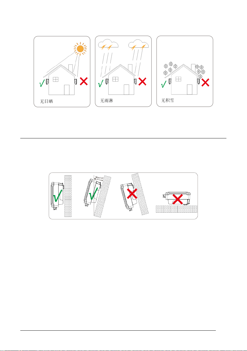
3. When designing or constructing a PV system, all components MUST remain in their
permitted operating ranges, and their installation requirements MUST always be
fulfilled.
4. Under exposure to sunlight, the PV array may generate dangerous output in DC
voltage. Contacts with the DC wires, conductors and live components in the inverter
may result in lethal shocks.
5. High voltages in inverter could cause lethal electrical shocks. Before proceeding any
work, including maintenance and/or service, on the inverter, fully disconnect it from
all DC input, AC grid and other voltage sources. There MUST be a 5-minute waiting
time after the full disconnection.
6. The DC input voltage of the PV array MUST never exceed the maximum input
voltage of the inverter.
7. DO NOT touch parts of the inverter during operation as heat will be induced and
these parts will exceed 60℃.

7 User Manual
3. 3UNPACKING
3.1 Scope of Delivery
Please inspect and check for completeness in the scope of delivery. Confirm with
purchase order.
1. DC Connector
HPT-30K/33K/36K 6 pairs
HPT-40K/50K 8 pairs
2. Wi-Fi/GPRS optional

User Manual 8
3.2 Product Overview
1. LED&LCD or LED
2. DC Switch
3. PV Terminal (s)
4. COM1: Wi-Fi/GPRS/RS485 port
5. COM2: Smart Meter port
6. COM3: RS485
7. AC Terminal
8. Secondary PE Terminal

9 User Manual
4. 4INSTALLING
4.1 Installation Requirement
1. Please install the inverter(s) in places that can avoid inadvertent contact.
2. Installation method, location and surface must be fitting for the inverter’s weight and
dimensions.
3. Please install the inverter in an accessible location for operation, future maintenance
and service.
4. The inverter performance peaks at ambient temperature lower than 45℃.
5. When installing in residential or domestic environment, it is recommended to install
and mount the inverter on a solid, concrete wall surface. Mounting the inverter on
composite or plaster boards or walls with similar materials would induce noise during
its operation and is therefore not recommended.
6. DO NOT cover the inverter NOR place any objects on top of the inverter.
7. To ensure sufficient room for heat dissipation and maintenance, the clearing space
between inverter(s) and other surroundings is indicated below for reference:

User Manual 10
8. Avoid direct exposure to sunlight and rain and snow layup.
4.2 Mounting Location
1. DO NOT mount the inverter near any inflammable materials.
2. DO NOT mount the inverter near any explosive materials.
3. DO NOT mount the inverter on tilting surface over 15°backwards. Please mount the
inverter on a vertical wall surface.
4. DO NOT mount the inverter on any surfaces tilting forward or to either sides.
5. DO NOT mount the inverter on a horizontal surface.
6. For easy installation and operation, please mount the inverter on a height that the
display could match eye level.
7. The bottom side where all commissioning terminals are equipped MUST always point
downwards.

11 User Manual
4.3 Mounting
Moving the inverter:
1. Use machinery or manpower to move the inverter according to the
situation on site.
2. It is recommended to move the inverter manually by at least two workers.
Protective shoes, gloves and other PPE’s (Personal Protective
Equipment ) are highly recommended. Focus on the pivot of the inverter
and prevent tiling the inverter.
3. When using lifting machinery, thread the rope through two lifting
handles on the upper side of the inverter. Pause when lifting the
inverter up to 100 mm above the ground, ensure tightness of rope, then
lift to the destination.
Wall-mounting the inverter
1. Use the mounting bracket as a template and drill holes of 10mm diameter and
70mm depth.
2. Fix the mounting bracket with the screws and expansion bolts packed in mounting
accessories.
3. Hold onto the handles on the inverter and tilt it slightly forward. Hang up the inverter
and attach it to the mounting bracket. Check both sides of the heat sink to ensure its
stably attached.
4. Observe from above, ensure the inverter has been securely attached to the bracket.
5. Use M5 screws (T25 screwdriver, torque 2.5 Nm) to attach the heat sink fins to the
mounting bracket.
It is recommended to attach the anti-theft lock to the inverter. Lock diameter φ4- 5.5mm
recommended.

User Manual 12
Racket-mounting the inverter:
In the same way as wall-mounting the inverter, only replace the expansion
bolts and screws with M10*45 Stainless steel full thread screw assembly (The
assembly incl. bolt, nut, flat washer, spring washer is not included in the
package)
4.4 Installing the secondary PE cable
1. Insert the grounding conductor into the suitable OT terminal lug and crimp the
contact.
2. Align the terminal lug with the grounding conductor and the ground washer on the
screw. The teeth of the ground washer must be facing the housing.
3. Tighten it firmly into the housing (M6 PE terminal, screwdriver type: Pan head,
torque: 4.5Nm).

13 User Manual
Information on grounding components:
Note: PE cable requirements
Object
Description
1
Housing
2
M6 terminal lug with protective conductor
3
M6×12 pan head screw
Diameter
Cross-section
备注
16<S≤35mm2
16mm2
Only suitable when the material of PE
cable is aligned with other AC phase
cables. In case the materials are
different, please ensure the resistance is
equivalent to the figure mentioned in
the table.
S>35mm2
S/2
Please install the secondary PE before connect any other cables.
Secondary PE cannot replace the connection of PE terminal in AC wiring. Both PE and
secondary PE should be properly installed.
Hypontech will not take account for any consequences caused by violating the
requirement.

User Manual 14
5. 5COMMISSIONING
5.1 Safety Instructions
1. Measure the frequency and voltage of grid connection and make sure they follow the
inverter’s grid connection specifications.
2. An external circuit-breaker on the AC side (or a fuse) at 1.25*AC rated current is
strongly recommended.
3. Reliability of all earth connections must be tested and valid.
4. Before commissioning, disconnect the inverter and the circuit-breaker or fuse, and
prevent accidental reconnection.

15 User Manual
5.2 AC Wire Assembly and Connection
5.2.1 AC Commissioning
AC cable requirement:
Five core flexible copper cable recommended, and strip the cable in such way:
Description
Value
A
Outer Diameter
HPT-30K/HPT-33K/HPT36K:22~30mm
HPT-40K/HPT-50K:30~50mm
B
Conductor cross-section
U,V,W,N线(HPT-30K/HPT-33K/HPT36K):
16~35mm²
U,V,W,N线(HPT-40K/HPT-50K):
铜线推荐35~50mm²
铝线推荐用70 mm²
PE线:见下表要求
C
N/PE Cable insulation strip
length
Approx. 90 mm
D
U/V/W Cable insulation strip
length
Approx. 70 mm
E
Cable insulation strip length
Approx. 20 mm
Make sure the strip length of PE is approx. 20 mm longer than L1、L2、L3 and N.
AC phase cable
cross-section
PE cable cross-
section
Note
16<S≤35mm2
16mm2

User Manual 16
Cable cross-section depends on the model of the inverter, ambient temperature, cable
routing method, cable type, cable losses and other installation requirements.
Aluminum cable requirements:
Copper aluminum transition terminal is obligated to prevent electrochemical
reaction.
Please follow the steps:
1. Disconnect AC circuit breaker and ensure it cannot be connected by accident.
2. Strip the cable as required.
3. Thread the cable through forcing nut of waterproof joint, sealing plug, waterproof
joint and junction box.
4. Insert the grounding conductor into the OT terminal lug in the accessory pack and
crimp the contact, ensure the insulation protection has been done properly.
S>35mm2
S/2
Only suitable when the material of PE
cable is aligned with other AC phase
cables. In case the materials are different,
please ensure the resistance is equivalent
to the figure mentioned in the table.
Danger due to high voltage electricity

17 User Manual
5. Insert PE, N, U, V and W cable into correspondent hole. And secure with cross
screwdriver (Torque: 4.5-6Nm).
6. Screw the junction box onto inverter.
False connection could damage the inverter

User Manual 18
5.2.2 AC Switch Types
Please install an individual 2-stage miniature circuit breaker according to the following
specifications:
Model
Maximum output
current(A)
AC Breaker Rated current
(A)
HPT-30K
50
63
HPT-33K
55
63
HPT-36K
60
80
HPT-40K
66.7
80
HPT-50K
80
100

19 User Manual
5.3DC Wire Assembly and Connection
1. PV modules of the connected strings must be of: the same time, identical alignment
and tilting angle.
2. Before commissioning and connecting the PV arrays, the DC switch MUST be open.
3. Parallel strings must have the same number of modules.
4. It is mandatory to use the DC connectors within package for the connection of PV
arrays.
5. The polarity of the PV arrays MUST be compatible to the DC connectors of the
inverter.
6. The DC input voltage AND DC input current of the PV array MUST never exceed the
maximum input allowance of the inverter.
DC Commissioning:
5.4 Residual Current Protection
This product is equipped with residual current protection device internally, in accordance
with IEC 60364-7-714. An external residual current protection device is not needed.
If the local regulation demands otherwise, it is recommended to install a 30mA Type B
residual current protection device.。

User Manual 20
6. 6 COMMUNICATION
6.1 System monitoring via Datalogger - RS485/Wi-Fi /GPRS
(Optional)
Wi-Fi /GPRS Datalogger Installation
1. Unpack the Datalogger from package.
2. Unscrew the cap in COM1 port and plug the Datalogger in and tighten.
3. For user guidance and configuration of Datalogger, please refer to the
corresponding HYPONTECH Wi-Fi Stick Guide manual, which is available in
printed form inside Documents pack, or an online manual on HYPONTECH
website at https://www.hypontech.com/xiazai
This manual suits for next models
4
Table of contents
Other Hypontech Inverter manuals