EVE MOONLESS 90 User manual

1
Cooker Hood
MOONLESS 90
บริษัท สยามแมเนอร์ กรุ๊ป จากัด
660 ซอยนวมิทร์ 81 แยก 3-42
แขวงนวมินทร์ เขตบึงกุ่มกรุงเทพฯ 10240
โทรศัพท์: 02-033-5400
โทรสาร: 02-033-5409
ศุนย์บริการหลังการขาย:
โทรศัพท์: 02-033-5422
www.eve.co.th
Instruction Manual

2
Content
1…………………………………..………………………………
2…………………………………..………………………………
3…………………………………..………………………………
4…………………………………..………………………………
5…………………………………..………………………………
6…………………………………..………………………………

3
a)
B)
•4 Pa (4 * 10-5
•
•
•
•
•
•–
•
•
•
•barbecue
•
•
•
•
4
Ref
1
1
2.1
1
2.2
1
3
1
4
1
5
2
(
1
Ref
10
7
5x50
11
7
Wall plug
12
6
ST4.2x9.5
20
1
21
1
5
MOONLESS 90

6
•
•970-1070 . A
•B A X 260-700.
•C 243 . A
•1 A, 80 .
•2 B, 60 .
•3 C, 100 .
7
/
•10 .
•wall plug ref11
• (ref 20) 3 ref 10ST5x50 A
•(ref21) 2 10ST5x50
B
•
•2 (ref 12)
•(ref21) 2 (ref12)
•(ref 20)
•
•2 (ref10) ST5x50 wall plug
•
120 .
150 .(120 .(ref 3) ref 4
)
•
•
•
•
•
8
•
• 120º
•
•
•(ref 2.2) (ref 2.1) B
•(ref 2.2) (ref 2.1) (ref 12)
1
1
2
2
➢
➢ !

9
3
3
/
capacitor
U
U
➢
10
:
•
•
:
•
•(et
:
()
•
•
•
•

11
✓
LED
•
•
•
•
•LED
•
•
ILCOS D code
,
1.5 w
DC 12V
DSR15S70
•
•
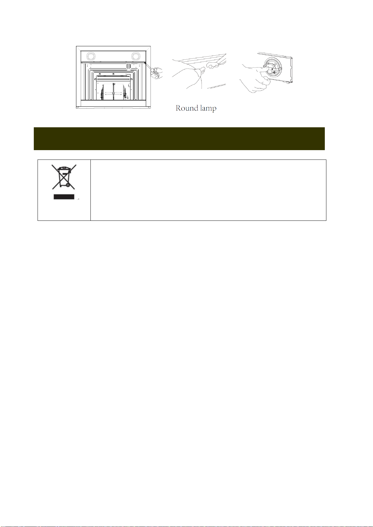
12
Directive 2012/19/EU
()
13
The instructions for Use apply to several versions of this applianceAccordingly, you
may find descriptions of individual features that do not apply to your specific appliance
INSTALLATION
•The manufacturer will not be held liable for any damages resulting from incorrect or
improper installation
•Check that the mains voltage corresponds to that indicated on the rating plate fixed to
the inside of the hood
•For Class I appliances, check that the domestic power supply guarantees
adequate earthing
•Connect the extractor to the exhaust flue through a pipe of minimum diameter
120mm
•The route of the flue must be as short as possible
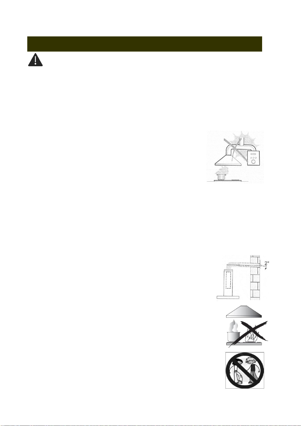
•Do not connect the extractor hood to exhaust ducts carrying combustion flumes
boilers, fireplaces, etc
•If the instructions for installation for the gas hob specify a greater distance specified
•The minimum distance between the supporting surface for the cooking vessels on the hob and the
•lowest part of the range hood is 650 mm
•Regulations concerning the discharge of air must be fulfilled
USE
•The extractor hood has been designed exclusively for domestic use to eliminate
kitchen smells
•Never use the hood for purposes other than for which it has been designed
•Never leave high naked flames under the hood when it is in operation
•Adjust the flame intensity to direct it onto the bottom of the pan only, making sure that
it does not engulf the sides
•Deep fat fryers must be continuously monitored during useoverheated oil can burst
into flames
•This appliance is not intended for use by persons including childrenwith reduced
physical, sensory, or mental capabilities, or lack of experience and knowledge, unless
they have been given supervision or instruction concerning use of the appliance by a
person responsible for their safety
•Children should be supervised to ensure that they do not play with the appliance
RECOMMENDATIONS AND SUGGESTIONS
14
•There shall be adequate ventilation of the room when the range hood is used at the same time as appliances burning
gas or other fuels not applicable to appliances that only discharge the air back into the room
•There is a fire risk if cleaning is not carried out in accordance with the instructions
•Do not flame under the range hood
•CAUTIONAccessible parts may become hot when used with cooking appliances
MAINTENANCE
•The cooker hood and its filter should be cleaned regularly according to the instruction
•Switch off or unplug the appliance from the mains supply before carrying out any maintenance work
•Clean the hood using a damp cloth and a neutral liquid detergent
•The appliance uses 4 hob elements at most
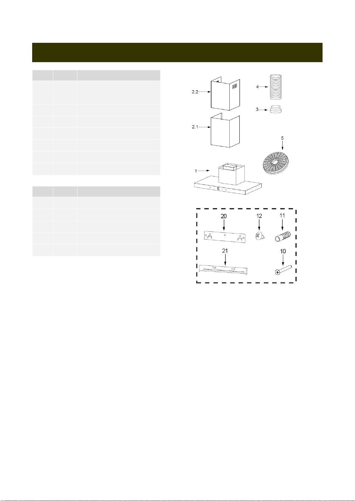
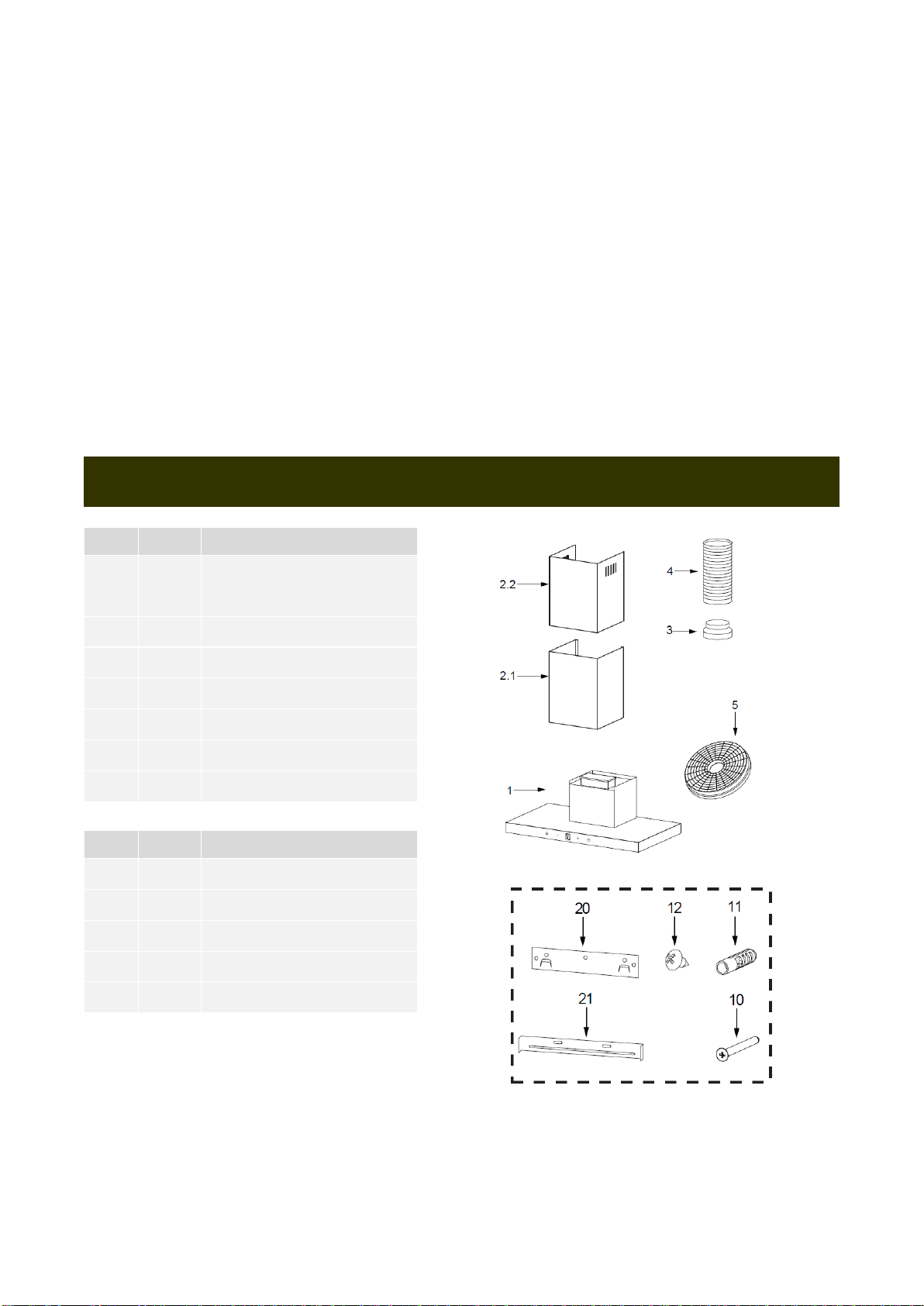
Ref
QTY
Components
1
1
Hood Body, complete with:
Controls, Light, Blower, Filter
2.1
1
Lower Decorative Chimney
2.2
1
Upper Decorative Chimney
3
1
Flange (Optional)
4
1
Exhaust Pipe
5
2
The Activated Charcoal Filter
1
Instruction Manual
Ref
QTY
Components
10
7
Screw5x50
11
7
Wall plugs
12
6
Screw ST4.2x9.5
20
1
Hood Fixing Bracket
21
2
Chimney Fixing Bracket
COMPONENTS
15
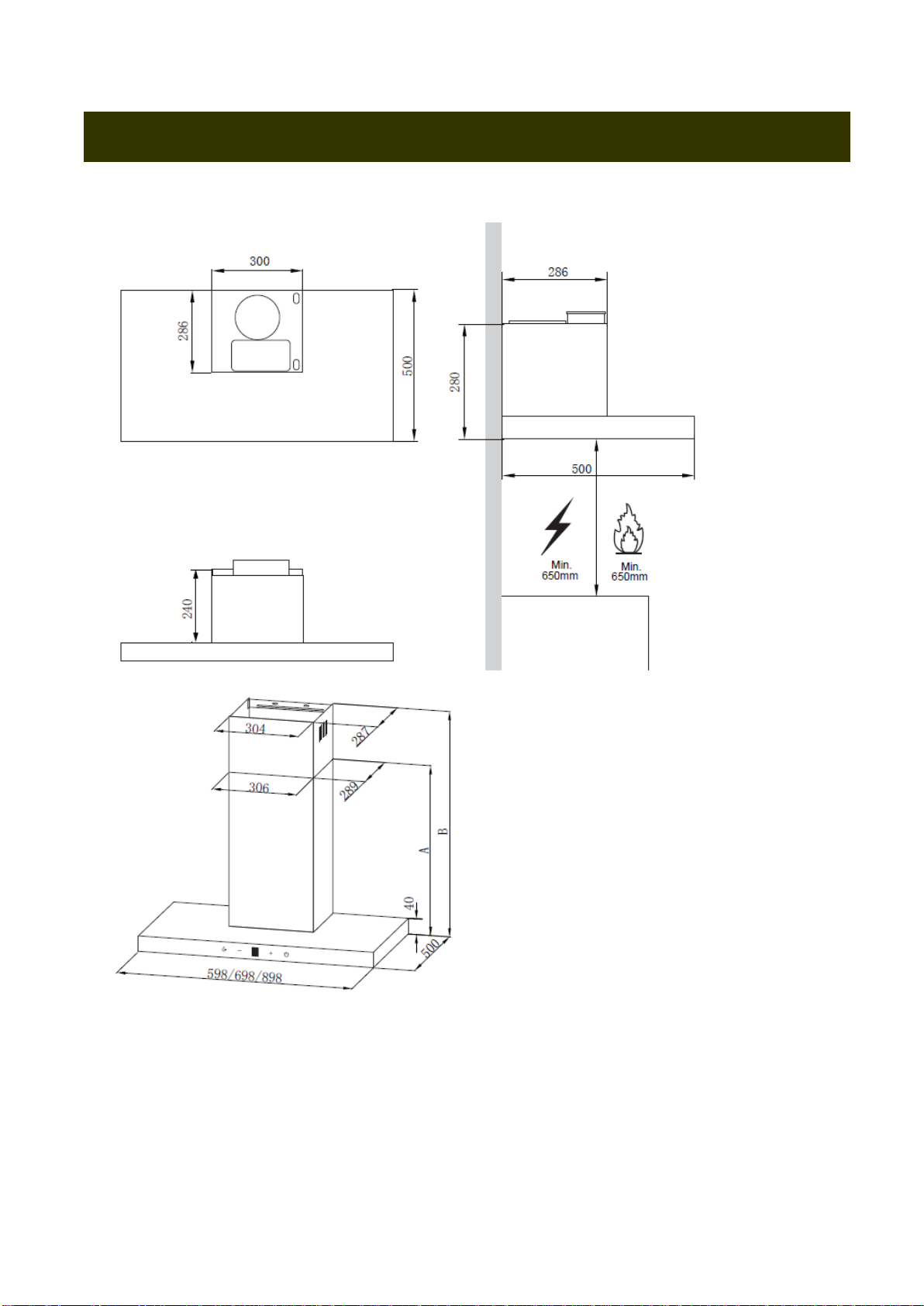
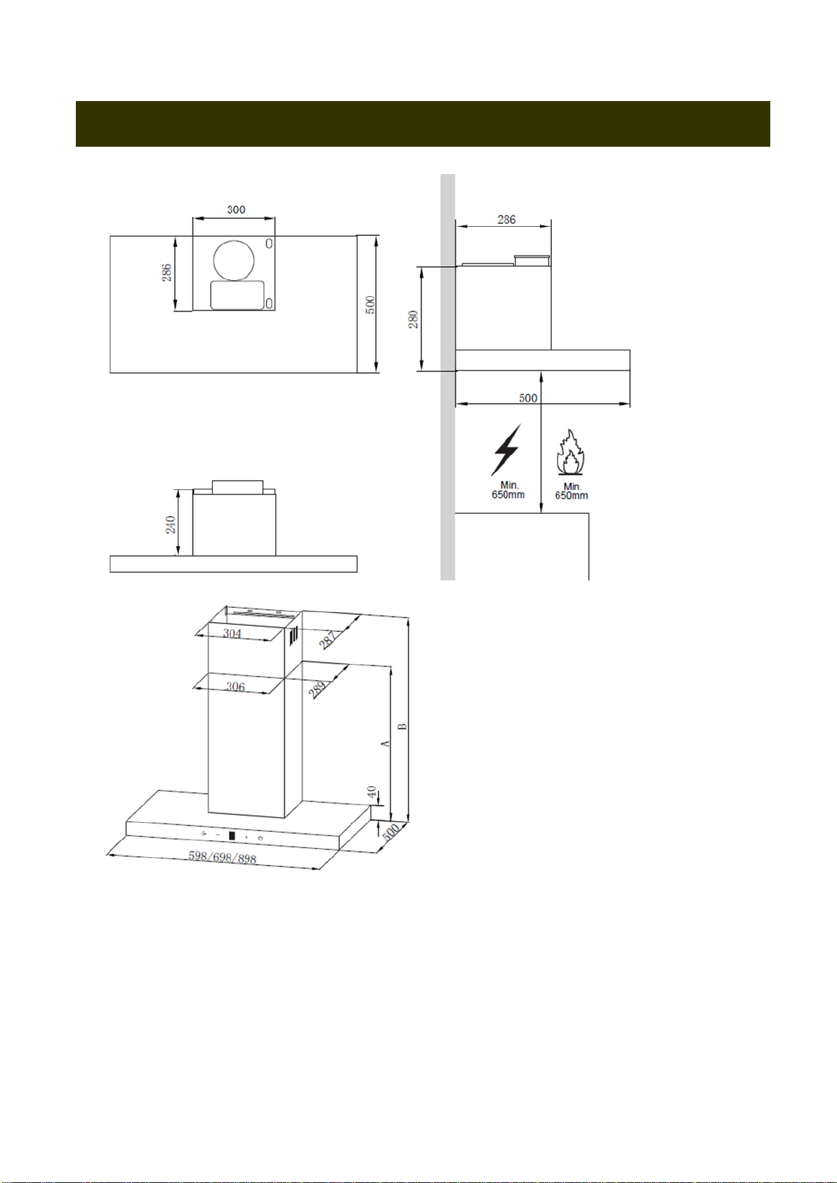
DIMENSION

16
As a first step, proceed with the following drawings
•A vertical line up to the ceiling or up to the upper limit, at the center of the area in which the hood
is to be fitted
•A horizontal line A at 970 –1070 mm above the cooker top
•A horizontal line B at a X mm above the horizontal line A
•A horizontal line C at a 243 mm below the horizontal line A
Mark Points
•Mark a point 1on the horizontal line A, 80 mm to the vertical reference line
•Repeat this operation on the other side and on the vertical reference line, checking that the
three marks are leveled
•Mark a point 2on the horizontal line B, 60 mm to the vertical reference line
•Repeat this operation on the other side, checking that the two marks are on the same
horizontal line
•Mark a point 3on the horizontal line C, 100 mm to the vertical reference line Repeat
this operation on the other side , checking that the two marks are leveled
INSTALLATION
Wall Drilling and Bracket Fixing

17
Fix the brackets
•Drill holes at the marked points with a ɸ10 mm drill bit
•Insert the Wall Plugs 11 into the holes
•Fix the hood fixing bracket 20 with 3 screws 10 5 x 50at the horizontal line A
•Fix a Chimney fixing bracket 21 with 2 screws 10 5 x 50at the horizontal line B
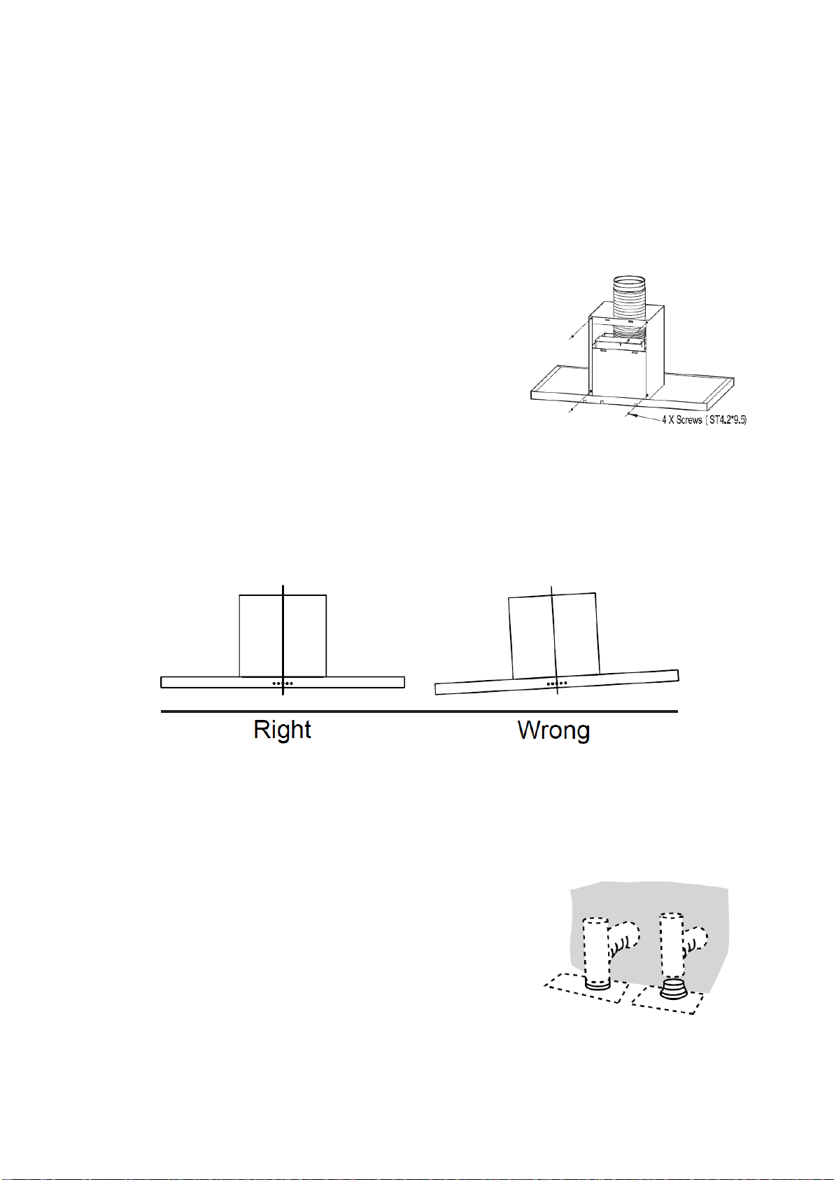
Lower decorative chimney
•Fix the exhaust pipe on the hood body,
•connect chimney and hood body with 2
•screws 12connect chimney fixing
•bracket and chimney with 2 screws 12
Hook the hood body
•Hook the hood body to the bracket 20
•Level the hood body itself
•Remove the filter from the inside of the hood body, fix the screws 10 to Wall Plugs 11 at
the points 3
CONNECTIONS
DUCTED VERSION AIR EXHAUST SYSTEM
When installing the ducted version, connect the hood to the chimney
using either a flexible or rigid pipe ɸ150 or ɸ120 mm, the choice of
which is left to the installer
•If to install a ɸ120 mm air exhaust connection, insert the reducer
•flange 3 on the hood body outlet
•Fix the pipe 4 in position using sufficient pipe clamps not
•supplied
•Remove possible charcoal filters
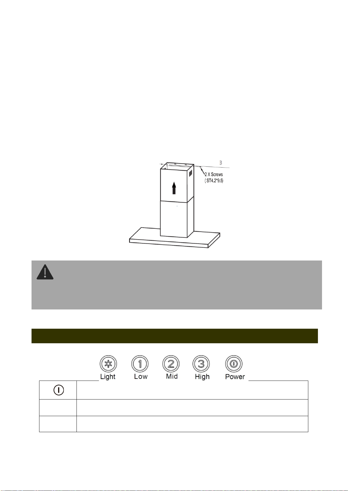
Upper Decorative Chimney
•Insert the upper decorative chimney 22 into the lower decorative chimney 21 and drag it up to the horizontal
line B

18
•Connect upper decorative chimney 22 and chimney fixing bracket 21 with 2 screws 12
Electronic Control
OFF MOTOR SWITCH: Press on this switch to stop the motor operation.
1
SPEED SWITCH: Press on this switch, the motor runs at LOW speed
2
SPEED SWITCH: Press on this switch, the motor runs at MEDIUM speed.
3
SPEED SWITCH: Press on this switch, the motor runs at HIGH speed.
ON/OFF LIGHTING SWITCH: Press on this switch to turn on
the lights and press again to turn them off.
USE

19
Fault
Cause
Solution
Light on, but
motor does not
work
The blades are blocked
Check the blades
The motor or capacitor is damaged
Contact the aftersales service to replace;
motor or capacitor
The internal wiring of motor is cut
offdisconnectedAn unpleasant smell
may be produced
Contact the aftersales service to replace
the motor
Both light and
motor do not
work
Apart from the above mentioned, check the following
Light damaged
Connect the wires as the electric
diagram
Power cord loose
Take down the outlet and seal with glue
Oil leakage
Outlet and the air ventilation entrance are
not tightly sealed
Take down the outlet and seal with glue
Vibration
The blade, if damaged, can cause
vibrating
Replace the blade
Insufficient
suction
The distance between the cooker hood
and the hob is too large
Readjust the distance
Too much ventilation from open doors or
windows
Choose a new place to install the
appliance or close some doors windows
The machine inclines
The fixing screws are not tight
enough
Tighten the fixing screw and make it
horizontal
TROUBLE SHOOTING
➢Our company will not be responsible for any damages or injury as a result of mis-usage, neglect, failure to keep
the product clean or incorrect installation by people or technicians whom are not our authorized technician.

20
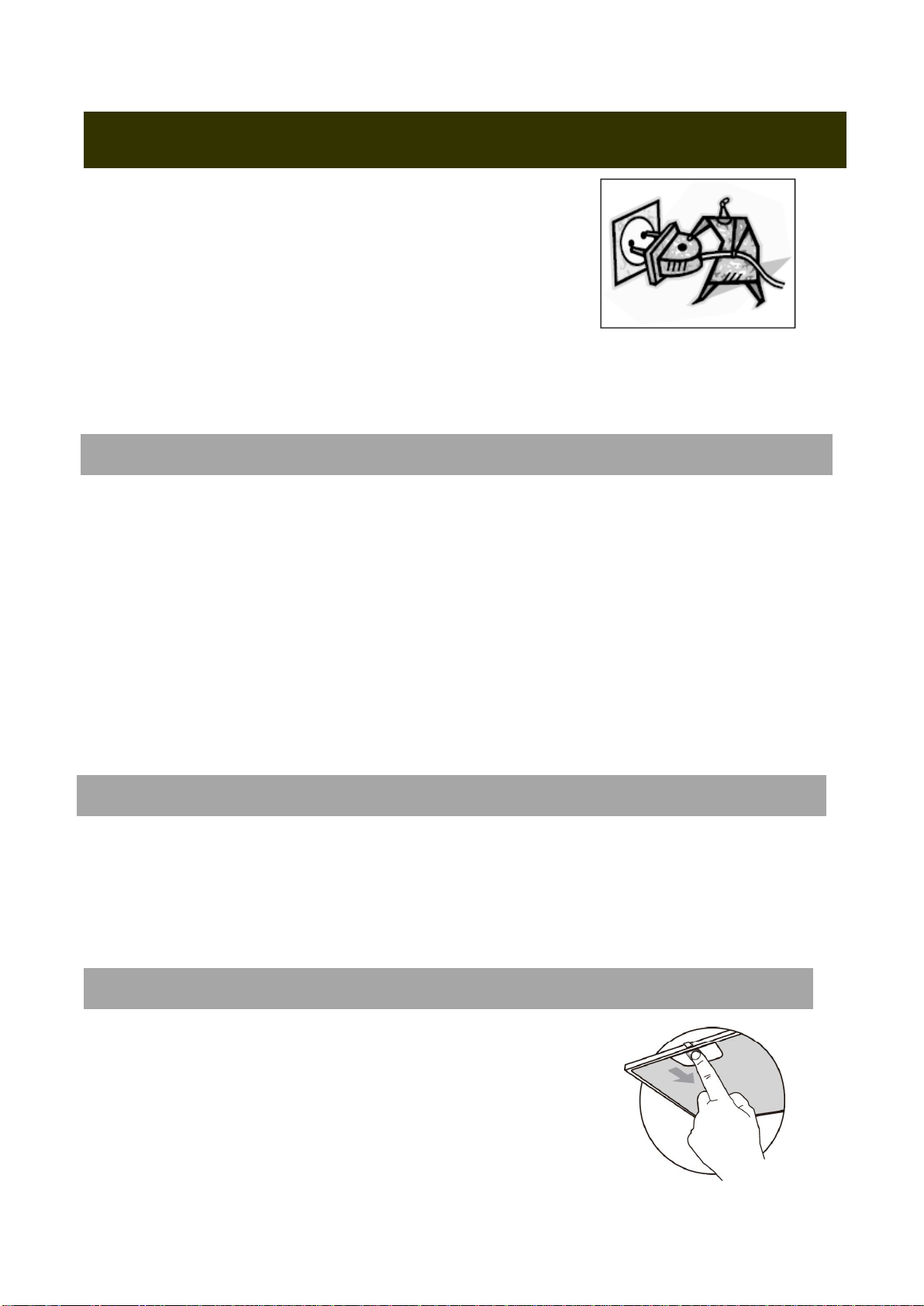
CAUTION:
•Please disconnect the power cord from the power socket before
any type of cleaning or maintenance
•Please follow the instruction below to avoid scratches, or marks
on the product
REMEMBER:
•Always clean the appliance when it has been cooled down
•Do not use the chemical or solution with high acidity such as bathroom detergent or vinegar as they cause
rust
CLEANING METAL SELFSUPPORTING GREASE FILTERS
•The filters must be cleaned every 2 months of operation, or
more frequently for particularly heavy usage, and can be
washed in a dishwasher
•Remove the filters one by one pushing them towards the back side of the hood
unit and simultaneously pulling downwards
•Any kind of bending of the filters has to be avoided when washing themBefore fitting them again into the hood
make sure that they are completely dryThe color of the filter surface may change throughout the time but this
has no influence to the filter efficiency
•When fitting the filters into the hood pay attention that they are mounted in correct position the handle facing
outwards
These filters are not washable and cannot be regenerated, and must be replaced approximately
every 4 months of operation, or more frequently with heavy usage
REPLACING THE ACTIVATED CHARCOAL FILTER
•Remove the metal grease filters
•Remove the saturated activated charcoal filter
•Fit the new filters
•Replace the metal grease filters
MAINTENANCE
ACTIVATED CHARCOAL FILTER RECIRCULATION VERSION
GREASE FILTERS
Table of contents
Languages:
Other EVE Ventilation Hood manuals

EVE
EVE HC-DIESEL-90 PLUS User manual

EVE
EVE Olympus 90 CM User manual

EVE
EVE HC-HEE35C-60 User manual

EVE
EVE Olympus 90 CM User manual

EVE
EVE HC-KRONOS-90 User manual

EVE
EVE HC-ARIA-90 User manual

EVE
EVE HC-HEE52TC-90 User manual

EVE
EVE HF-BK102AT-60 User manual

EVE
EVE BLAST 90 CM User manual

EVE
EVE HF-HSM102AT-60 User manual

Popular Ventilation Hood manuals by other brands


Miele
Miele DA 1050-55 Operating and installation instructions

IKEA
IKEA VINDRUM user manual

Greentek
Greentek SOLACE Series Installation and operation manual

Franke
Franke FLI 625 XS Instructions for use and installation

FALMEC
FALMEC Design Plane 90 Inox Instruction booklet

Cookology
Cookology CHA600BK instruction manual


