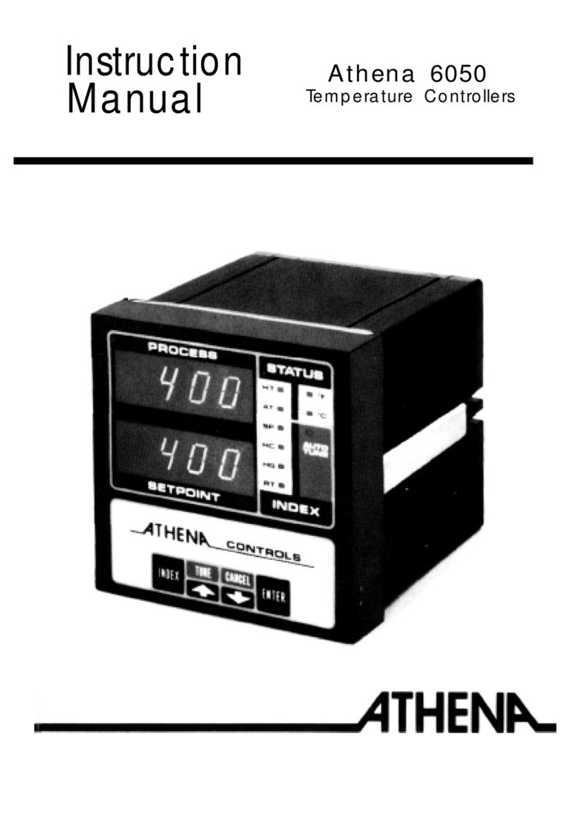
Ever Cool TC140 Manual

Operating & Instruction Manual - © tc140 v06
Ever Cool Ltd, Viglen House Business Centre, Alperton Lane, London HA0 1HD
Tel: 020 8601 7157 Fax: 020 8997 0395 Web: www.evercoolltd.co.uk E-Mail: info@evercoolltd.co.uk
Company Registration No: 6096265 Company VAT No: 809764984
Pressurized Water Circulating
Temperature Control Unit
Model TC140
Operating & Maintenance Instruction Manual
Temperature Control & Refrigeration

Ever Cool Ltd, Viglen House Business Centre, Alperton Lane, London HA0 1HD
Company Registration No: 6096265 Company VAT No: 809764984
INDEX
1. Safety
2. General Safety Precautions (during servicing)
3. Noise Emissions
4. Introduction and General Description
5. The Fluid Circuit –water unit.
6. Heating and cooling
7. The Fluid Pump
8. The Electrical System
9. Installation –Water Unit
10.Starting Unit
11.Inputting Set Temperature Valve
12.Adjusting Additional Control Parameters.
13.Alarm List, Drawings, Certification
Ever Cool Ltd, reserve the right to change the design and specification of these
machines without previous notice.

Ever Cool Ltd, Viglen House Business Centre, Alperton Lane, London HA0 1HD
Company Registration No: 6096265 Company VAT No: 809764984
1. Safety
Every effort is made to ensure that products can be used safety, but it is essential
that all users should be aware of the hazards present and act accordingly. The
following information must be bought to the attention of all persons involved with the
equipment. This handbook refers to a:
Ever Cool Pressurized Temperature Control Unit.
Many parts, including external ones such as hose connections and filters are hot
during operation. Such parts remain hot for some time after the equipment has been
switched off. They may cause blistering or burns if touched before they have had
time to cool.
The temperature controller is electrically powered at mains voltage. It must be
correctly earthed in accordance with the installation section of this handbook and
with local regulations for electrical supply. All electrical and mechanical interlocks,
guards and other safety devices fitted when delivered must be kept in place. They
must be inspected at regular intervals by competent personnel.
Examinations or repair must not be attempted by untrained persons. The equipment
must be completely isolated from the electrical supply and all parts allowed to cool
down, including those surrounded by thermal insulation, before any covers are
removed. The equipment must not be adjusted or modified for use in a non –
standard manner without first seeking advice from Ever Cool Limited.
All hoses and ancillary devices connected to the equipment must be of suitable
quality to withstand the operating temperature and internal pressure specified in this
handbook.
Flexible hoses connected by the user should be installed according to the re –
commendations of the hose manufacturer, especially in regard to minimum bending
radius, and care should be taken to avoid wear or damage during use.
All pipework, particularly flexible hoses, valves and other apparatus should be
inspected regularly by qualified personnel. Equipment should be taken out of service,
until rectified, at any sign of damage of leakage.
In certain circumstances, internal pressure may be present with sufficient force to
cause injury. No part of the fluid circuit, whether internal or external to the
equipment, should be released until the temperature of all parts is at 50°C or below.

Ever Cool Ltd, Viglen House Business Centre, Alperton Lane, London HA0 1HD
Company Registration No: 6096265 Company VAT No: 809764984
2. General Safety Precaution (During Servicing)
Disconnect from supply
Secure against re –activation
Confirm de –energisation
Cover or provide barriers for adjacent live components
Never stand on temperature controller –always access ladders, it may be
considered necessary to provide protection to personnel form any leakage
however caused. Equipment design is under constant review and changes
may be made to improve quality. If any other information is required, or if
there is any doubt regarding safe installation or application of the equipment,
please contact: Ever Cool Ltd on +44(0)208 601 7157.
3. Noise Emissions
For assessment of the noise levels in the work area in which the unit is to be
used the following information is provided:
PRESUMED NOISE LEVEL POWER = LWA 80 (ISO 3746)
4. Introduction & General Description
Each temperature control unit has been designed for efficiency and ease of
operation with high reliability. It is one of a range of similar products designed to
cover very diverse performance needs in process temperature regulation.
This handbook gives details of design, operation and maintenance for the TC 140
pressurized unit.
DO not begin installation or servicing without being sure of the model and the
operating voltage (look at the front panel and serial plate on the back).
5. The Fluid Circuit - Water Unit
MAXIMUM WATER INLET PRESSURE FOR TC 140 (Pressurized units) IS 4 BAR
IMPORTANT: REDUCE PROCESS WATER TEMP TO BELOW 50°C BEFORE
REMOVING HOSES.
IMPORTANT: DRAIN THE UNITS BEFORE YOU TAKE OUT THE PROCESS
HOSES

Ever Cool Ltd, Viglen House Business Centre, Alperton Lane, London HA0 1HD
Company Registration No: 6096265 Company VAT No: 809764984
6. Heating & Cooling
Heating elements are made from low watts density incoloy to present undue built up
of scaling. The heat exchanger (COOLER) is a weld plate to minimize the effect from
uneven expansion and to give a large cooling surface for greater performance.
7. The Fluid Pump
The pump is of Magnetic Drive Pump.
8. The Electrical System
Some details of the electrical system, for maintenance purposes, are in the date
sheet of this manual. Please note: the control voltage is 24V. Always check carefully
before fitting replacement parts.
Power ON/OFF is the RED handle on the front panel which interlocks with the mains
isolator.
All control switches are LED indicators are identified by icons for easy recognition of
functions and faults.
Heater and pumps contactors and pump overload are all housed in the self
contained electrical cabinet. This lies behind the front panel which hinges
downwards for easy access.
Heating and cooling functions are switched on and off automatically by the printed
circuit board. This is achieved with a hybrid PCB circuit board and a J type
thermocouple.

Ever Cool Ltd, Viglen House Business Centre, Alperton Lane, London HA0 1HD
Company Registration No: 6096265 Company VAT No: 809764984
9. Installation - Water Unit
Connecting up and filling with water
Position the unit as near as possible to the equipment to be controlled
A. Connect the “water inlet” at the back of the unit to the factory mains or chilled
water supply and the “drain outlet” to a drain, using suitable hoses (refer to
the drawing of rear panel hose connections).
B. Check that the process circulation and external pipework is clean and free
from lime or particulate matter which could reduce heat transfer or damage
the pump. Clean out if necessary. Connect the “to load” and “from load”
connections at the back of the unit using hoses which MUST BE SUITABLE
for operating temperature and pressures as follows:
FOR 140°C UNITS –HOSE RATING (minimum) = 150°C AND 6 BAR
C. Ensure that the panel mounted isolator is switched off, the front panel is
hinged at the bottom and will swing forward and down.
D. Connect the terminals of the unit’s mains isolator to a suitable electrical
supply (check serial plate at back) by means of an appropriately rated power
cable and connect the earth. Electrical connections must be carried by a
professional personnel.
E. If external isolation valves have been fitted, open them to admit mains water
to the unit. Also ensure that all connections to process and drain are open.
N.B
In normal condition the pump will run in a CLOCKWISE direction when viewed
from the front through the motor vent. If the pump is running in an anti –
clockwise direction swap two phase connections over.

Ever Cool Ltd, Viglen House Business Centre, Alperton Lane, London HA0 1HD
Company Registration No: 6096265 Company VAT No: 809764984
10. Starting Unit
Fill the tank until the LED (minimum level) is extinguished. The unit
will fill automatically from the cooling water supply.
Check hose connections are tight and switch on the pump.
On initial start-up the pump may start and stop automatically due to pressure build
up in the system.
Less than 80°C the unit will automatically bleed air through BLUE HOSE.
Cooling water will flow through heat exchanger to keep away scaling build up in the
heat exchanger.
With the pump selection switch in the O (central) position, neither the pump nor the
heating will function.
11. Inputting Set Temperature Value
Upon switching on the unit, the set temperature value and the measured process
value will appear in the digital display.
Press < and the first digit to be set will flash. Press keys to set the value and to
confirm the data. Repeat the operation for the other digits.
AUTOTUNING function (automatic search temperature)
Pressing during 10 seconds T sign will appear in the display when this sign
disappears the unit will have the suitable parameters for one precise process
temperature.
12. Adjusting Additional Control Parameters
It is not normally necessary to change any control parameters other than the set
temperature value as described above. However, the electronic circuit of the unit has
six additional control parameters from SET 0 to SET 8.
To change the set values to additional SET control parameters, press and
simultaneously for 25 seconds, will visualize the first SET press to go the
wanted SET press will appear the first valve, press again to allow change dates
press and the first digit to be set will flash modify it with keys press
confirm.

Ever Cool Ltd, Viglen House Business Centre, Alperton Lane, London HA0 1HD
Company Registration No: 6096265 Company VAT No: 809764984
SET 0 (ST-0)
SET 0 has four sublevels:
pb, ti, td
and
cy
.
pb
: Proportional valve of process.
ti
: Integral process time.
td
: Process derived
cy
: Process action cicle
SET 1 (ST-1)
SET 1 has two sublevels:
Db.cl
and
Crcl
.
Db.cl: Cooling on delay (factory set at 2).
Example: Set temperature value: 80
o
C
Db.cl set at 2 will energise the cooling solenoid valve at 82
o
C.
Crcl : Cooling relative gain ( factory set at 0,4 )
If the cooling water is from one chiller you can change it to a 0,2.
to allow change datas press
and the first digit to be set will flash modify
it with
keys press to confirm.
SET 2 (ST-2)
Internal adjustment, non accessible.
SET 3 (ST-3)
SET 3 has three sublevels :
AO.H, AO.L
and
AO.S
AO.H High oulet tension limit 4-20mA
AO.L Low oulet tension limit 4-20mA
AO.S Sign oulet tension limit 4-20mA
Only for units working with
current loop
system.

Ever Cool Ltd, Viglen House Business Centre, Alperton Lane, London HA0 1HD
Company Registration No: 6096265 Company VAT No: 809764984
SET 4 (ST-4)
SET 4 has five sublevels :
Bias : Correction Offset of the temperature
Unidad : Possibility to work in ºC or ºF
Out L : Limit percentage heaters power.
Sp.ll : Minimum set point process temperature
Sp.hl : Maximum set point process temperature.In water machines the
Value is 95 while in oil machines is 200.
SET 5 (ST-5)
DEF: Default to preset factory settings. Set to 100 to revert all SET
parameters back to factory settings.
SET 6 (ST-6)
LEVF locking function
Value 0: Denies access to all levels
Value 1: Allows access to all levels
SET 7 (ST-7)
COMS Communications interface activation On / Off
Addr Address assigned to the circuit
bAud Transmission speed 0-1-2 0 = 2400, 1 = 4800, 2 = 9600
PAr Parity bit 0-1-2
dEn TCU unit working with interface 4-20m Amp
must put value “1” If customer work with one TCU unit but if
costumer works with several TCU units all TCU units must be set
with value “0” less the last one it must be set with value “1”
TCU unit working with interface RS 485
must put value “1” in all TCU units.

Ever Cool Ltd, Viglen House Business Centre, Alperton Lane, London HA0 1HD
Company Registration No: 6096265 Company VAT No: 809764984
SET 8 (ST-8)
In.LE Selection level detection buOy magnetic sensor ELEC
electrode.
dC.ti Pump connection time when we reach the optimum water level.
CO.ti Disconnection pump time for low water level.
iP.AC Activation view of process pressure transmiter. On/Off
iP.AL Maximum value alarm inlet pressure.
iP.LL Viewing minimum scale inlet pressure.
iP.FS Viewing background scale inlet pressure.
rP.AC Activation pressure transmiter for the regulation process
rP.AL Alarm pressure. Maintain pressure in the process.
rP.LL Minimum pressure level scale process.
rP.FS Background process pressure scale.
13. Alarm List
Err on the lower display = flow alarm (no flow) or open external thermocouple.
Ouer the lower alarm display = open thermocouple
HEAt at the lower temperature alarm display = (depends on how we have
programmed)
Red LED pump off front panel pump thermal protection (pump stop)
Red LED Fluid Level front panel Lack of fluid pressure if it is pressurized
equipment.

Ever Cool Ltd, Viglen House Business Centre, Alperton Lane, London HA0 1HD
Company Registration No: 6096265 Company VAT No: 809764984
Electronic PCB Card Connections

Ever Cool Ltd, Viglen House Business Centre, Alperton Lane, London HA0 1HD
Company Registration No: 6096265 Company VAT No: 809764984
Hydraulic Drawing

Ever Cool Ltd, Viglen House Business Centre, Alperton Lane, London HA0 1HD
Company Registration No: 6096265 Company VAT No: 809764984
PCB Card Diagram

Ever Cool Ltd, Viglen House Business Centre, Alperton Lane, London HA0 1HD
Company Registration No: 6096265 Company VAT No: 809764984

Ever Cool Ltd, Viglen House Business Centre, Alperton Lane, London HA0 1HD
Company Registration No: 6096265 Company VAT No: 809764984
EC Certificate of Conformity
Hereby certifies that
MACHINERY: Pressurised Water Circulating Temperature Control Unit
Is manufactured in conformity with the Commission Directive 98/37/EEC
(Machinery Directive) relating to the approximation of the laws of the Member States
relating to machinery, with particular reference to Annex 1 of the directive, relating to
essential health and safety requirements related to the design and manufacture of
machinery.
is manufactured in conformity with the Commission Directive 89/336/EEC (EMC
Directive) relating to the approximation of the laws of the Member States relating to
protection for radio communication and equipment, devises or systems, whose
function could be impaired by electromagnetic interference caused by electric and
electronic devices.
Is manufactured in conformity with the Commission Directive 73/23/EEC(Low
Voltage Directive) relating to the approximation of the laws of the Member
States relating to electrical equipment.
Is manufactured in conformity with harmonised standards: EN294, EN 60204-1.
Manufactured For Ever Cool Limited
Ever Cool Limited
Viglen House Business Centre
Alperton Lane
London
HA0 1HD
UK
T: 020 8601 7157

Ever Cool Ltd, Viglen House Business Centre, Alperton Lane, London HA0 1HD
Company Registration No: 6096265 Company VAT No: 809764984
Ever Cool Limited Warranty
1. All products are warranted under normal usage and service against defects in workmanship or
materials for a period of twelve months from date of shipment. Ever Cool ltd will repair or replace
at its option any product or components it finds defective.
2. This warranty is limited to the cost of the original product and is in lieu of all other express or implied
warranties and excludes the loss of or profits, or any other direct or indirect incidental or
consequential damages caused by the product failure or delay in remedying same.
3. This warranty shall not be enforceable if the purchaser is in default or delay in making full payment
for the product.
4. This warranty does not cover failures caused in whole or in part, but not necessarily limited, to the
under noted causes:
- Improper application
- Operation outside of design limitations
- Incorrect electrical connection
- Low/high voltage + or –6% rated voltage
- Power interruptions –phase failure/reversal or power spikes.
- Product is used with refrigerants or oil agents that are not compatible with the materials
of construction or authorized by the manufacturer.
- Product failure is attributed to dirt or moisture entering the system, or in the case of
refrigeration equipment, liquid slugging on the low pressure side.
5. Claims for products subject to failure within the terms of this warranty must be submitted in
accordance to the following procedure:
The purchaser must complete the Ever Cool ltd warranty claim form in full and attach a copy of their
engineers report with an official purchase order on Ever Cool ltd stating customer order reference
numbers, unit serial numbers and that the order is subject to “Investigate for Warranty Order” and on
return to Ever Cool ltd within ten days of failure (with copies accompanying any product requested to be
returned). If in the event the product is not repairable and pending evaluation of the claim, the
supplier may at his discretion provide a replacement product ex-works that would be invoiced to the
purchase in the normal way. If the purchaser claim is accepted within the scope of the warranty, a
credit note will be issued within 30 days of approval. Should the claim, in our opinion, fall outside the
terms of the warranty period due to any of the aforementioned exclusions or late submittal of claim or
lapse of warranty period or any reasonable justification giving Ever Cool ltd cause to reject the claim,
no credit note will be issued and the full invoice value will become due within the purchaser’s agreed
terms with Ever Cool ltd.
In the event the purchaser requests the supplier (or the supplier requires) to examine the product/s
on site or their factory to determine more fully the likely cause of failure, Ever Cool ltd reserves the
right at their discretion to charge all costs of such examinations to the purchasers account, if upon
examination the cause of failure is deemed to fall outside the warranty provisions. Product/s subject
to warranty claim should not be disposed of until any outstanding matters have been concluded.
Product/s should not be returned to the supplier unless specifically requested to do so.
Failure to adhere to the procedures outlines and to the time limits stipulated may give grounds to
reject the claim.
Table of contents
