EVEREST REFRIGERATION EPR1-24 User manual

Owner’s Manual
Food Prep Table Refrigerators
Side Mounted Condensing Unit
EPR1, EPR1-24, EPR2, EPR2-24, EPWR2, EPR3,
EPPR1, EPPSR2, EPPR2, EPPR3, EPPR1-D2,
EPPR2-D2, EPPR2-D4, EPPR3-D2, EPPR3-D4
www.everestref.com

this page intentionally left blank

Food Prep Table Refrigerators
EPR1, EPR1-24, EPR2, EPR2-24, EPWR2, EPR3, EPPR1, EPPSR2, EPPR2,
EPPR3, EPPR1-D2, EPPR2-D2, EPPR2-D4, EPPR3-D2, EPPR3-D4
Everest Owner’s Manual
Contents
Hydrocarbon Guidelines ���������������������������� 1, 2
Installation Instructions ������������������������������� 3, 4
General Safety ������������������������������������������������ 9
Electrical Safety �������������������������������������������� 10
Operation ������������������������������������������������ 11–15
Care and Maintenance ���������������������������� 16,17
Troubleshooting Guide ���������������������������18–20
Warranty Information ������������������������������21–23

Hydrocarbon Guidelines
1
Hydrocarbon Guidelines
DANGER - Risk of fire or explosion. Flammable refrigerant used. Do not use mechanical devices or
other means to accelerate the defrosting process. Do not puncture refrigerant tubing.
DANGER - Risk of fire or explosion. Flammable refrigerant used. To be repaired only by trained service
personnel. Do not puncture refrigerant tubing.
CAUTION - Risk of fire or explosion. Flammable refrigerant used. Consult Service Manual or Owner’s
Manual before attempting to install or service this product. All safety precautions must
be followed.
CAUTION - Risk of fire or explosion. Flammable refrigerant used. Dispose of properly in accordance
with federal or local regulations.
CAUTION - Risk of fire or explosion due to puncture of refrigerant tubing; follow handling instructions
carefully. Flammable refrigerant used.
WARNING - THIS UNIT USES R290, A HYDROCARBON, PROPANE REFRIGERANT THAT IS
ENVIRONMENTALLY FRIENDLY BUT IS ALSO HIGHLY FLAMMABLE AND EXPLOSIVE. PLEASE
READ THIS MANUAL CAREFULLY AND FOLLOW ALL SAFETY PRECAUTIONS CONTAINED HEREIN
TO AVOID THE RISK OF FIRE OR EXPLOSION. FAILURE TO FOLLOW THE SAFETY PRECAUTIONS
MAY RESULT IN SERIOUS INJURY, OR DEATH, AND/OR PROPERTY DAMAGE.
This section applies to R290 Hydrocarbon units only. To identify the refrigerant type,
see the data plate in the cabinet interior.

Hydrocarbon Guidelines 2
PROPANE (R290) IS HIGHLY APPROVED FOR USE AS A REFRIGERANT IN COMMERCIAL,
SELF-CONTAINED UNITS IN THE US UNDER LIMITED USE CONDITIONS. IT CAN ONLY BE
USED IN NEW EQUIPMENT. BACKFITTING OR MODIFICATIONS OF OLD EQUIPMENT ARE
NOT ALLOWED. IT MUST BE CHARGED IN A STRICTLY LIMITED VOLUME OF UP TO 150
GRAMS (5.3 OZ) PER REFRIGERATION CIRCUIT. EVEN THOUGH THIS IS A SMALL AMOUNT,
IT STILL PRESENTS A FIRE OR EXPLOSION HAZARD IF IT LEAKS OUT OF PARTS THAT
HOLD REFRIGERANT. WHEN IT COMES IN CONTACT WITH AIR, A FLAMMABLE PROPANE-AIR
MIXTURE CAN BE CREATED AND EASILY IGNITED BY ELECTRICAL SPARKS, OPEN FLAMES OR
HOT SURFACES. THE RISK IS HIGHER IN SMALL, CONFINED, POORLY VENTILATED SPACES.
PROPANE WILL SETTLE AT LOWER ZONES BECAUSE IT IS HEAVIER THAN AIR. TO REDUCE
THESE RISKS, OBSERVE THE FOLLOWING PRECAUTIONS
• Avoid installation of unit in areas with open flames or in general vicinity of open flames or high
surface temperatures.
• Avoid unit installation in small, confined spaces. Ensure ample ventilation at all times. Keep all
exhaust vents free of any blockage or obstruction.
• Do not rely on smell to detect potential leaks of propane refrigerant. Propane refrigerant is a
high purity propane gas and does not contain odorants or stenching agents. These additives are
typically used in fuel-grade propane and natural gas in order to give them a distinctive smell which
makes it easier to detect leaks.
• General service and repairs must be performed in well-ventilated areas.
• General service and repairs must be performed only by professionals authorized by Everest
Refrigeration.
• Component shall be replaced with Everest-issued, like components to minimize the risk of possible
ignition resulting from incompatible parts or improper repairs.
• Do not modify, re-appropriate, or remove any functional part(s) from the unit.
• Handle the unit with care to avoid any damage.
• Practice safety guidelines when transporting the unit. Consult with your local Department of
Transportation for requirements in moving flammable gasses.

3Installation Instructions
Installation Instructions
1. Inspect for any freight damage upon delivery
of the unit. If damage is detected, immediately
report it to an Everest representative. Everest
is not responsible for damage that occurs
during shipment.
2. Keep the unit upright at all times. The
compressor contains oil, refrigerant, lubricants
and various chemicals. When tilted, these
fluids may shift and travel to sections where
they don’t naturally occur. This will lead to
system contamination and compressor failure.
3. Some units require caster installation for
proper performance. Visit our website at www.
everestREF.com and enter your product’s
model number in the search field to determine
its caster requirements.
4. Do not place your hands under the top surface
lip or on the unit chassis when moving it to
avoid injury from sharp edges, protruding parts
or weight impact.
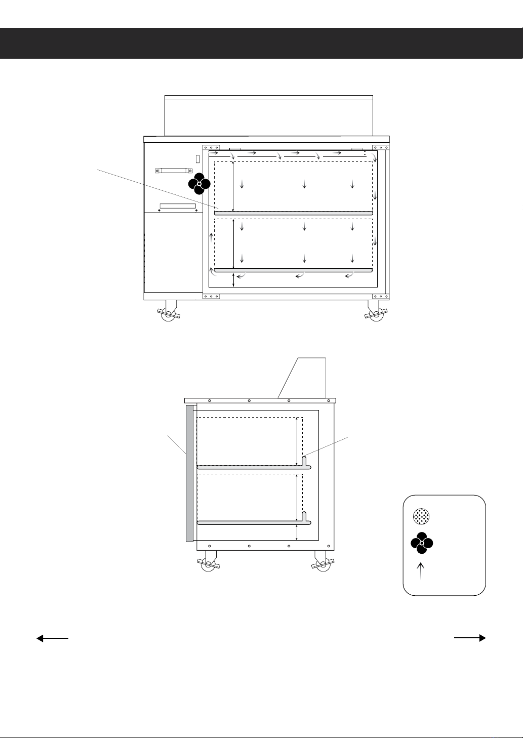
5. Select a location with good air ventilation.
Poor ventilation rapidly increases ambient
temperature. High ambient temperatures
exceeding 86°F (30°C) promote excessive
compressor activity in order to maintain the
desired cabinet temperature. This will result in
decreased performance, advanced component
failure and the risk of fire.
6. Position the unit so it’s front and left vents
as well as top pan area are away from
heat-generating equipment such as stoves,
ovens, etc. Heat sources rapidly increase the
temperature of the immediate vicinity. High
temperatures exceeding 86°F (30°C) promote
excessive compressor activity in order to
maintain the desired cabinet temperature. This
will result in decreased performance, advanced
component failure and the risk of fire.
7. A distance of 6” is required for back side
and left side clearance. This ensures proper
ventilation and prevents overheating which can
lead to advanced component failure and the
risk of fire.
8. Select a location with a hard, leveled surface.
Use a leveling tool on the unit to ensure
proper alignment. Proper door function and
condensate removal is dependent on accurate
balance. Install the front leg stabilizers for units
that come standard with it to ensure proper
door / drawer functions and unit stability.
9. Select a location close to an electrical wall
outlet to ensure direct connection without the
use of extension cords.
10. Select a location away from severe moisture
conditions. This may compromise the unit’s
electrical components and lead to electrical
shocks or the risk of fire.
11. Select a location that will not expose the unit
to extremely dusty conditions. Environments
with high dust and debris content will
significantly hasten condenser blockage and
will result in decreased performance, advanced
component failure and the risk of fire.
12. Do not build an enclosure or cabinet around
the unit. This will restrict air ventilation
resulting in elevated compressor activity,
decreased performance, advanced component
failure and the risk of fire.
13. The unit is not intended for use in food trucks.
Limited space, lack of ventilation and ambient
temperatures exceeding 86°F (30°C) typical to
this setting will result in elevated compressor
activity, decreased performance, advanced
component failure and the risk of fire.
14. The unit is intended for indoor use only.
Outdoor use will cause a decrease in
performance, advanced component failure
and the risk of fire.
This section applies to all Everest products. Correct installation ensures proper performance
and longevity of your appliance. Professional installation by a trained refrigeration technician
and electrician is recommended. Warranty is void if the following guidelines are not met.

4
Installation Instructions
Shelf Installation
Some models come standard with shelves, shelf clips and notched pilasters.
Each shelf requires four clips.
1. Attach the shelf clips onto the pilasters by inserting
its top hook into a pilaster notch followed by the
bottom hook. Do not use pliers or other crimping
tools to modify the shape of the shelf clips. This will
result in shelf mounting instability.
2. Place shelves on the shelf clips making sure all
corners are mounted securely and evenly with
identical distance from the unit’s floor and up.
Always lay the back of each shelf down on the rear
clips before the front.
3. When removing a shelf, unmount the shelf from the
shelf clips. To detach the shelf clip from the pilaster,
tilt up the shelf clip until the bottom hook clears,
followed by the top hook.

5Installation Instructions
Product Load Levels
EP Series
Front Rear
Side View
Airflow Guard
Door
Load Level 9”
Load Level 9”
2”
Front View
2”
Load Level 9”
Load Level 9”
Shelf
Air Vent
Fan
Airflow

6
Installation Instructions
Top Pan Configurations
All food prep. table models come standard with top pans and pan dividers. Follow the top pan
configuration shown in the illustration. Always keep pans in their slots even when empty.
This ensures that refrigerated air does not escape.
Side Mount Sandwich Prep. Tables
EPR1
Standard:
(8) 1/6 size pans (6" deep)
w/ (3) pan dividers
1/6 1/4 1/6 1/3 1/2 1/6 1/6 1
EPR2
Standard:
(12) 1/6 size pans (6" deep)
w/ (5) pan dividers
1/6 1/4 1/3
1
1/2
Pan Size Variations
Side Mount Pizza Prep. Tables
EPPR1
Standard:
(4) 1/3 size pans (6" deep)
w/ (3) pan dividers
EPPSR2
Standard:
(7) 1/3 size pans (6" deep)
w/ (5) pan dividers
EPPR2
Standard:
(9) 1/3 size pans (6" deep)
w/ (7) pan dividers
EPPR3
Standard:
(12) 1/3 size pans (6" deep)
w/ (9) pan dividers
1/3 1/6 1/4
1/2 1
1/3
1/3 1/6 1/4 1/6
1/6 11/2 1/6
1/6 1/4 1/6 1/2 1/6 1/6 1
1/3 1/6
1/2 1
1/4
1(full) 1/2 1/2
1/4 1/4
1/4 1/4
1/6 1/6 1/6
1/6 1/6 1/6
Pan Size Variation
1/3 1/3 1/3
†: Pan count applicable for units manufactured from May 2016
1/9
Standard:
(8) 1/9 size pans (4" deep)
w/ (3) pan dividers
EPRI-24
Standard:
(12) 1/9 size pans (4” deep)
w/ (5) pan dividers
EPR2-24
1/9

7Installation Instructions
Top Pan Configurations (Continued)
†: Pan count applicable for units manufactured from May 2016
EPR3 †
Standard:
(18) 1/6 size pans (6" deep)
w/ (8) pan dividers
1/
61/4
1
1/3
1/2
Side Mount Pizza Prep. Tables
EPPR1
Standard:
(4) 1/3 size pans (6" deep)
w/ (3) pan dividers
EPPSR2
Standard:
(7) 1/3 size pans (6" deep)
w/ (5) pan dividers
EPPR2
Standard:
(9) 1/3 size pans (6" deep)
w/ (7) pan dividers
EPPR3
Standard:
(12) 1/3 size pans (6" deep)
w/ (9) pan dividers
1/3 1/6 1/4
1/2 1
1/3
1/3 1/6 1/4 1/6
1/6 11/2 1/6
1/6 1/4 1/6 1/2 1/6 1/6 1
1/3 1/6
1/2 1
1/4
1(full) 1/2 1/2
1/4 1/4
1/4 1/4
1/6 1/6 1/6
1/6 1/6 1/6
Pan Size Variation
1/3 1/3 1/3
EPWR2 †
Standard:
(16) 1/6 size pans (6" deep)
w/ (7) pan dividers
1/6 1/4
1/6
1/2
1/6 1/3
1/6
1

8
Installation Instructions
Drawered Pan Configurations
Some food prep. models are equipped with drawers. Drawer pans are not included with the
product as standard and must be purchased separately. Purchase standard pans according to
the size specified in the drawer pan configuration.
†: Pan count applicable for units manufactured from May 2016
Side Mount Pizza Prep. Tables
EPPR1
Standard:
(4) 1/3 size pans (6" deep)
w/ (3) pan dividers
EPPSR2
Standard:
(7) 1/3 size pans (6" deep)
w/ (5) pan dividers
EPPR2
Standard:
(9) 1/3 size pans (6" deep)
w/ (7) pan dividers
EPPR3
Standard:
(12) 1/3 size pans (6" deep)
w/ (9) pan dividers
1/3 1/6 1/4
1/2 1
1/3
1/3 1/6 1/4 1/6
1/6 11/2 1/6
1/6 1/4 1/6 1/2 1/6 1/6 1
1/3 1/6
1/2 1
1/4
1(full) 1/2 1/2
1/4 1/4
1/4 1/4
1/6 1/6 1/6
1/6 1/6 1/6
Pan Size Variation
1/3 1/3 1/3
EPPR1-D2†
1
1/4
1/4
1/4 1/4
1/4
(1) Pan divider per drawer included (6" deep)
Pan Size Variations
Side Mount Pizza Prep. Tables
EPPR1
Standard:
(4) 1/3 size pans (6" deep)
w/ (3) pan dividers
EPPSR2
Standard:
(7) 1/3 size pans (6" deep)
w/ (5) pan dividers
EPPR2
Standard:
(9) 1/3 size pans (6" deep)
w/ (7) pan dividers
EPPR3
Standard:
(12) 1/3 size pans (6" deep)
w/ (9) pan dividers
1/3 1/6 1/4
1/2 1
1/3
1/3 1/6 1/4 1/6
1/6 11/2 1/6
1/6 1/4 1/6 1/2 1/6 1/6 1
1/3 1/6
1/2 1
1/4
1(full) 1/2 1/2
1/4 1/4
1/4 1/4
1/6 1/6 1/6
1/6 1/6 1/6
Pan Size Variation
1/3 1/3 1/3
EPPR2-D2†• EPPR2-D4†• EPPR3-D2†• EPPR3-D4†
(1) Pan divider per drawer included (6" deep)
1/2
1
1/4 1/6
1/3
Drawered Pizza Prep. Tables
Side Mount Pizza Prep. Tables (Cont.)

9General Safety
• Before the unit is used, it must be installed and connected according to the installation instructions
provided in this manual.
• Remove all packaging material and protective vinyl covering from the unit before it is used.
These items are flammable and can lead to a fire.
• Do not store or use gasoline or other flammable vapors and liquids in the vicinity of the unit.
Do not store combustible or explosive items and substances such as aerosol cans in or around
the vicinity of the unit.
• Do not place objects on or around the exhaust vents of the unit. This can cause overheating
which may lead to a fire or explosion. Objects may also fall when opening and closing doors
which may lead to serious injury.
• Do not place any weight on top of the unit nor use it as a stand. This can damage the unit’s
structural integrity.
• If you suspect a refrigerant leak or a compromised refrigeration system, disconnect the unit,
and contact Everest Refrigeration immediately.
• When disposing the unit, remove all doors and trays to avoid any risk of injury or entrapment.
Ensure that the refrigerant in the condensing unit is properly disposed of by a qualified
refrigeration technician according to governmental codes, requirements, and regulations.
General Safety
This section applies to all Everest products. Use your appliance according to its designed
function as specified in this Owner’s Manual. Warranty is void if the following guidelines
are not met.

10
Electrical Safety
Everest units come as 115 volts, 60 hertz,
single phase.
Everest units in this family are equipped with a
NEMA 5-15P. A 15 amp breaker must be used
for units that come with a NEMA 5-15P plug.
The ground prong must not be removed to reduce
the risk of electric shock and related hazards.
If the grounding pin is missing, the cord must
be removed from use. If the outlet is a standard
2-prong outlet, it must be replaced with the
properly grounded 3-prong wall outlet. Only
a qualified electrician may install the correct
power source.
To guarantee electrical safety, the wall outlet and
circuit must be checked by a qualified electrician
to make sure it is properly grounded.
Remove debris from the power plug prongs
with a soft cloth or brush before connecting
it to an outlet.
Assign the unit to a dedicated, undamaged
electrical circuit with a voltage rating that
matches the data plate. Check the incoming
voltage with a multi-meter. This avoids the
overloading and overheating of circuit wires
which may lead to a fire.
Do not use extension cords, adapter plugs or
other third party electrical connections. Everest is
not responsible for issues resulting from improper
electrical connections, electrical power failures
and voltage fluctuations.
Everest does not recommend the use of
generators in conjunction with the unit due
to voltage fluctuations that may compromise
electrical components.
Turn off the unit using the power button before
unplugging. Wait at least 5 minutes before
re-plugging to prevent damage to the compressor.
Do not unplug the unit by tugging on the power
cord. Grip the plug and pull it securely out of the
outlet.
Prevent damage to the power cord by providing
sufficient clearance around and under the unit.
Do not use a power cord that shows cracks or
exposed wires. Power cords that have been
severely worn or damaged must be replaced
with original manufacturer parts and only by
an authorized technician.
Electrical Safety
115/60/1
NEMA 5-15R
This section applies to all Everest products. Basic safety precautions must be observed when
using electrical appliances in addition to the following. Warranty is void if these guidelines
are not met.

11 Operation Guidelines
Starting your Everest Product
After plugging in the unit, the current temperature and compressor symbol will appear on the
digital temperature control’s LED display. will flash at short intervals for 1 minute after which the
compressor(s) and condenser fan motor(s) will initiate. At the beginning of every compressor cycle,
the condenser fan motor is automated to rotate in reverse for 30 seconds in order to blow dust off the
condenser coil.
The evaporator fan motor(s) will initiate once the evaporator coil reaches a specific temperature
relative to the digital temperature control setting and for as long as the door is closed. A fan symbol
will appear on the LED display to indicate that the evaporator fan is running.
Allow the unit to operate for 24 to 72 hours before storing contents in the cabinet. This lets the cabinet
temperature fully stabilize. Use this time to verify proper installation and operation.
The interior light and evaporator fan motor is controlled by a door switch for solid door models and a
rocker switch for glass door models.
The default temperature setting is 35.0°F (2.0°C) for refrigerators and -4.0°F (-20.0°C) for freezers.
The factory recommended temperature range is between 33.0°F (1.0°C) to 40.0°F (4.0°C) for
refrigerators and -5.0°F (-21.0°C) to 0°F (-18.0°C) for freezers. Setting the temperature outside of the
recommended range will cause performance issues and in some cases may result in component failure
that is outside of warranty coverage.
The compressor, condenser and evaporator fan motors run while the unit is on refrigeration cycle.
The compressor, condenser and evaporator fan motors stop running while the unit is on defrost cycle.
The unit is preset to defrost every 5-6 hours with a duration of 45 minutes or less depending on the
evaporator coil temperature. Changing the preset outside of the default range will result in cooling
issues and advanced component failure.
The digital temperature control is intended to read and display the cabinet’s air temperature, not actual
food product temperature. The displayed temperature may fluctuate due to frequent or prolonged door
operation. The most conclusive method to determine a unit’s cooling performance is to measure the
food product’s temperature using a digital food thermometer.
Operation
Use your Everest product according to its intended functions. Warranty is void if the following
guidelines are not met.

12
Operation Guidelines
Everest units are equipped with a Carel Digital Temperature Control. The type of controller is
dependent on the model and production date.
Setting the Temperature
1. Press and hold Temperature Set Button for 2 seconds until the LED blinks
SET alternating with a number. The blinking number is the current set temperature.
CAUTION:If PS appears on the LED
This means the Temperature Set button was held down longer than 3
seconds. To exit this mode and restart, press Temperature Set Button
Alarm in Progress
Compressor Running
Power / Up Button
Cabinet in Defrost
Manual Defrost / Down Button
Evaporator Fan Running
Temperature
Set Button
Cabinet Temperature
Carel ‘Easy’ Digital Temperature Control

13
2. Toggle through the desired temperature by pressing UP or DOWN The number increases
or decreases by a decimal point.
3. The recommended setting is 35.0°F (2.0°C) for refrigerators and -4.0°F (-20.0°C) for freezers. The
available temperature setting range is 33.0°F to 54.0°F (1.0°C to 12.0°C) for Refrigerators and -10.0°F to
54.0°F (-23.0°C to 12.0°C) for Freezers.
4. Press and hold the Temperature Set Button for 3 seconds to save the new temperature and exit
the setting mode. The LED will return to the current cabinet temperature.
Initiating Manual Defrost
The controller has an automatic defrost cycle in place so initiating manual defrost is not
necessary unless there is an abnormal accumulation of ice around the evaporator coil.
1. Press and hold down the Manual Defrost Button until the Defrost Symbol
appears on the LED display.
The compressor, condenser and evaporator fan motors will stop running.
The refrigeration system will remain in defrost cycle for 45 minutes or until the
evaporator coil reaches the safety termination temperature setting.
Setting the Temperature ( continued )
Operation Guidelines

14
Setting the Temperature
1. Press and hold Temperature Set Button for 2 seconds until a number blinks on the LED. The blinking
number is the current set temperature.
2. Toggle through the desired temperature by pressing UP or DOWN. The number increases or
decreases by a decimal point.
3. The recommended setting is 35.0°F (2.0°C) for refrigerators and -4.0°F (-20.0°C) for freezers. The
available temperature setting range is 33.0°F to 54.0°F (1.0°C to 12.0°C) for Refrigerators and -10.0°F to
54.0°F (-23.0°C to 12.0°C) for Freezers.
4. Press and hold the Temperature Set Button for 3 seconds to save the new temperature and exit the
setting mode. The LED will return to the current cabinet temperature.
Everest units are equipped with a Carel Digital Temperature Control. The type of controller is dependent on
the model and production date.
Carel ‘ir33’ Digital Temperature Control
Compressor Running
Cabinet in Defrost
Evaporator Fan Running
Cabinet Temperature
Alarm in Progress
Error
Up Button /
Auxillary
Down Button /
Manual Defrost
Program Button
Temperature Set Button
Operation Guidelines

15
The controller has an automatic defrost cycle in place so initiating manual defrost is not necessary
unless there is an abnormal accumulation of ice around the evaporator coil.
1. Press and hold down the Manual Defrost Button until the Defrost Symbol appears on the
LED display.
The compressor, condenser and evaporator fan motors will stop running. The refrigeration system
will remain in defrost cycle for 45 minutes or until the evaporator coil reaches the safety termination
temperature setting.
Operation Guidelines
Initiating Manual Defrost

16
Care and Maintenance
• Unplug the unit before cleaning, repairing or replacing parts.
• Do not spray the exterior of unit with water to avoid electric shock, component malfunction
or the risk of fire.
• Do not use any flammable cleaning products on or around the unit to prevent the risk of fire.
• Do not use household or industrial chemical cleaners, acidic or chlorine based solutions,
degreasers, wire brushes, scrapers, steel pads, acidic solutions or other abrasive products.
• The unit is equipped with a washable condenser coil filter. The filter builds up lint, dust and grease
overtime and will require monthly cleaning. A clogged condenser coil filter will result in decreased
performance, advanced component failure and a risk of fire. See page (9) for condenser coil filter
cleaning instructions.
• Conduct regular inspection of the sliding door tracks to ensure that the sliding doors are
closing properly. Clean any debris that could potentially cause blockage in the tracks.
• Clean the interior of the unit with mild soap and warm water. Remove the interior drain hole
plug to allow water to drain out. Ensure that the exterior drain hoses are connected to the rear
of the unit. Wipe interior until dry.
• Clean the exterior of the product with mild soap and water. Do not use steel wool, strong acids,
concentrated detergents, bleaches, cleaning waxes, polishers and other abrasive cleaners.
Do not allow moisture to come in contact with electronic parts to avoid any risk of fire.
• Acidic products and products containing vinegar must be stored in sealed containers to prevent acid
damage to the interior of the unit and the evaporator coil. Rust resulting from improper maintenance
is not covered under warranty.
Care and Maintenance
This section applies to all Everest products. Regular care and maintenance of your appliance
will significantly extend service life and dependability. In severe cases, lack of upkeep will
contribute to the rapid decline in performance and component health. Care and maintenance is
the product owner’s personal responsibility. Warranty is void if these guidelines are not met.

17 Care and Maintenance
Condenser Coil Air Filter Cleaning Instructions
It is necessary to clean the condenser coil monthly to ensure that it is free of lint, dust and grease
build-up. Warranty is void if the following guidelines are not met.
1. Ensure that the unit is disconnect from
the outlet before performing maintenance.
2. Use a long bristled brush in a vertical
sweeping motion to remove lint, dust and
debris from in between the metal fins of
the condenser coil. Do not apply heavy
pressure so as not to bend the fins.
3. Use a commercial condenser coil cleaner
for metal fins that are coated in grease.
Allow the cleaner to saturate the area.
Follow the recommended wait time
printed on the product packaging.
4. The grease and cleaning solvent will
pool at the base of the metal fins. Brush
the fins and wipe off any accumulated
residue.
5. Repeat the above steps until the metal
fins are clean. You should be able to see
in through and in between the metal fins.
6. Reconnect the unit to the designated
outlet.
1 2
3
5
4
6
Do not attach an aftermarket filter or screen around the condenser coil.
This constricts ventilation which leads to overheating, component failure
or the risk of fire.
This manual suits for next models
14
Table of contents
Other EVEREST REFRIGERATION Commercial Food Equipment manuals
Popular Commercial Food Equipment manuals by other brands

Eurocryor
Eurocryor TWIN MINI SV User instructions

Victory
Victory HS Installation and operating instructions

Henny Penny
Henny Penny Evolution Elite EEE-141 quick guide

Alphalux
Alphalux E-DBW-11-21 instruction manual

Redfox
Redfox PP 70/04 Instructions for installation and use

Diamond
Diamond DSM/2-20 A operating instructions