Everfine LT- 101A User manual

LT- 101A
LED DRIVER TESTER
USER’S MANUAL
V 1.05
EVERFINE Corporation (Stock Code: 300306)
ADD :Bldg.1 #669 Binkang Rd., Binjiang Hi-Tech
Zone, Hangzhou(310053), China
Tel :86-571-86698333
Fax :86-571-86696433
E-mail:Global@everfine.net
Globalservice@everfine.net
http://www.everfine.net
Copyright © EVERFINE, Copy or spread without authorization is prohibited.


LT-101A User’s Manual
Copyright © EVERFINE, Copy or spread without authorization is prohibited. 1
Foreword
Thank you for purchasing the EVERFINE LT-101A LED Driver Tester. This user’s
manual contains useful information involving the instrument’s functions and operating
procedures as well as precautions that should be noticed during operation. In order to
use the instrument correctly, please read the manual carefully first, then put it in a
right place for quick references.
Notes:
EVERFINE pursues a continuing improvement of the performance and functions
of its products, therefore, the contents of this manual may be changed without
prior notice.
Great effort has been made in preparation of this manual to ensure the accuracy of
its contents. However, if you have any questions or find any errors, please contact
your dealer or EVERFINE sales office.
If you have different understanding to this manual, please refer to the Technical
Service Department of EVERFINE.
Checking package contents
Please check the instrument carefully when you unpack the box for the first time. If
the instrument and related accessories are missing or appear abnormal, please contact
the dealer immediately.
Warm notice to valued customers of EVERFINE
"Ensure the quality, insist on continuous improvement and make every customer
more satisfied" is the quality policy of EVERFINE. Therefore, the quality of
products and services provided by EVERFINE should be better than those have
been promised. If you have further suggestions or advices on our products and
services, please provide your feedback to our quality supervision department.
Your supervision is the motivation for us to move forward!

LT-101A User’s Manual
Copyright © EVERFINE, Copy or spread without authorization is prohibited.
2
Copyright Statement
The copyright of this manual and the related information belong to EVERFINE,
and it is protected by the copyright law of Peoples’ Republic of China and other
relevant international treaties. Copying, modifying, spreading, excerpting,
backing up or translating the whole or part contents of this manual by any
company or personnel without the written permission of EVERFINE is
prohibited. Otherwise it will be treated as infringement and the infringer will
assume law responsibility and all loss of EVERFINE. Any infringement related
above can be traced back to the responsible user by the unique product number
printed in the manual.
If EVERFINE has signed a written agreement with user and the contents in the
agreement are in conflict with above terms, the contents in the written agreement
have preferential force effect.

LT-101A User’s Manual
Copyright © EVERFINE, Copy or spread without authorization is prohibited. 3
Safety precautions
The following general safety precautions must be observed during all phases of
operations, including repairing. If the instrument is used in the manner not specified in
this manual, the function may be hindered.
1. LT-101A is a precise instrument, avoid collision while being conveyed to other
places.
2. Power supply should be AC220V±5%, 50Hz/60Hz。
3. Please do not dismantle or remove the cover as the internal precise devices may be
damaged.
4. During the test, do not touch the connection terminals to avoid electric shock.
5. Check the connections carefully before measurement.
6. Grounded well.

LT-101A User’s Manual
Copyright © EVERFINE, Copy or spread without authorization is prohibited.
4
Contents
Foreword........................................................................................................................ 1
Copyright Statement.......................................................................................................2
Safety precautions.......................................................................................................... 3
Contents..........................................................................................................................4
Chapter 1 Overview........................................................................................................6
Chapter 2 Fundermentals................................................................................................7
2.1 System structure of LT-101A............................................................................7
2.2 Schematic diagram of LT-101A........................................................................7
2.3 Main functions...................................................................................................8
2.4 Digital display................................................................................................... 9
Chapter 3 Specifications...............................................................................................10
3.1 Main specifications..........................................................................................10
3.2 General specifications..................................................................................... 10
Chapter 4 Preparations................................................................................................. 12
4.1 Panel descriptions............................................................................................12
4.2 Measurement connections............................................................................... 15
Chapter 5 Operations....................................................................................................16
5.1 Input characteristics test at steady state...........................................................16
5.2 Output characteristic test at steady state..........................................................17
5.3 Start-up characteristic test............................................................................... 18
5.4 Other operations.............................................................................................. 19
Chapter 6 Software Instructions................................................................................... 21
6.1 System requirement.........................................................................................21
6.2 Installation....................................................................................................... 21
6.3 Operation......................................................................................................... 21
6.4 Test reports (shown in the attached pages)......................................................29
Chapter 7 Verification...................................................................................................30
7.1 Verification conditions.....................................................................................30

LT-101A User’s Manual
Copyright © EVERFINE, Copy or spread without authorization is prohibited. 5
7.2 Verification equipments...................................................................................30
7.3 Items and methods...........................................................................................30
Appendix...................................................................................................................... 33

LT-101A User’s Manual
Copyright © EVERFINE, Copy or spread without authorization is prohibited.
6
Chapter 1 Overview
LT-101A LED Driver Tester is a reliable, cost-effective and powerful instrument
which is specially designed for the measurement of input and output electrical
performance of LED drivers. The upper & lower limit of the main parameters for
automatic judgment can be preset, and it will alarm while exceeding the limits. It can
work independently, and can also communicate with a computer. LT-101A is very
suitable for site-test like production lines, quality inspections and R&D of LED
drivers, etc.
LT-101A User’s Manual
Copyright © EVERFINE, Copy or spread without authorization is prohibited. 7
Chapter 2 Fundermentals
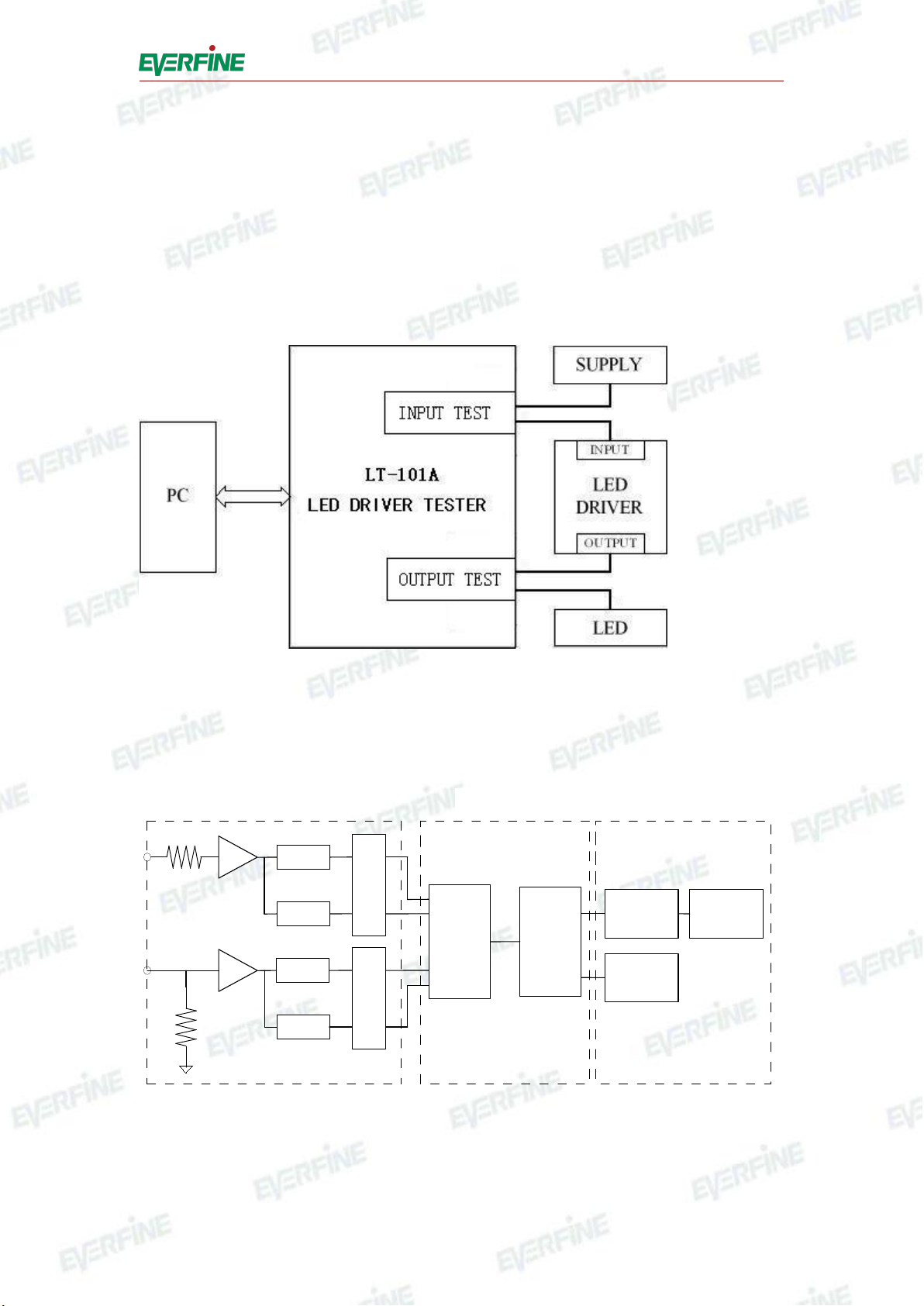
2.1 System structure of LT-101A
The system structure of LT-101A is shown in figure 2.1. The device can both work
independently and communicate with the computer testing system.
Fig.2.1 System structure of LT-101A
2.2 Schematic diagram of LT-101A
A/D
ISO.
ZERO
FPGA DSP
KEY&LED
CONTROLLER
RS-232-C
/RS-485
KEY&LED
A/D
ISO.
ZERO
INPUT CPU INTERFACE
V
A
Fig.2.2 Schematic diagram of LT-101A
Schematic diagram of LT-101A is shown in figure 2.2, The LT-101A device can

LT-101A User’s Manual
Copyright © EVERFINE, Copy or spread without authorization is prohibited.
8
test the input and output of the LED driver simultaneously.
2.3 Main functions
2.3.1 Steady state characteristics test of LED drivers
The test mode for input and output characteristics at steady state can be set in RMS or
DC individually, and it also has power-down protection function.
(1) Input characteristics test
The input electrical quantities measured of LED drivers at steady state include RMS
values of voltage and current, peak values of voltage and current, total harmonic
distortion of voltage and current, harmonic current at one watt, frequency, active
power, power factor, waveform of voltage and current, the initial phase, peak phase
and end phase of current. The order of harmonic analysis can be up to 50 times.
(2) Output characteristics test
The output electrical quantities measured of LED drivers at steady state including
voltage, current, active power, frequency and power efficiency.
2.3.2 Start-up characteristics test of LED drivers
(1) Input characteristics test
Measure the input peak values of voltage and current at 0~40ms after starting LED
drivers. The software can draw the curves of voltage and current during this time to
calculate and display the start-up time according to related standards .
(2) Output characteristics test
Measure the Max.Voltage, Max.Current and the time to Max.Current within 0~3s
from startup. The software provides two testing modes: conventional start-up mode
and transient start-up mode. Under conventional start-up mode, it can draw the 0~3s
start-up curves of voltage and current; while under transient start-up mode, it can
draw the 0~40ms start-up curves of voltage and current.

LT-101A User’s Manual
Copyright © EVERFINE, Copy or spread without authorization is prohibited. 9
2.4 Digital display
This instrument is equipped with a 7-segment LED and some restricted characters.
The numbers and characters are shown as follows:
Initialization display
1. Light all the numeral LED tubes;
2. Extinguish all the numeral LED tubes;
3. Display "EVERFINE LT-101A, FPGA VX.XX CPU VX.XX", "CALC XXXX",
"MODE XXX", where "VX.XX" is the version number, "CALC" means calibrated by
the manufacturer. If "XXXX" is "PASS", it means the instrument is eligible, while
"ERR" means disqualification. “IN MODE” means the input test mode, and “OUT
MODE” means the output testing mode. If “XXX” is "RMS", it means real effective
value. If “XXX”is "DC", it means direct current.
0: A: K: U: ( )
1: B: L: V:
2: C: M: W:
3: D: N: X:
4: E: O: Y:
5: F: P: Z:
6: G: Q: :
7: H: R: :
8: I: ( ) S: :
9: J: T: :

LT-101A User’s Manual
Copyright © EVERFINE, Copy or spread without authorization is prohibited.
10
Chapter 3 Specifications
3.1 Main specifications
3.1.1 Input and Output characteristics measurement
Item
Voltage(V)
Current(A)
Range
300V
1A/5A
Measuring range
3V~300V(CF=3)
0.010A~5.000A(CF=3)
Maximum allowable input
600V
10A
Frequency range
DC, basic frequency:20Hz~65Hz
Band width
Narrowband:20Hz~5kHz;Broadband:20Hz~1MHz
3.1.2 Basic error (accuracy of the instrument)
Condition
Item
Basic error
Ambient temperature: 23℃±5℃
Relative Humidity: 30%RH~75%RH
Voltage: 220V±11V
Input waveform: stable sine wave
Input range: 10%~100% Full Scale
common-mode voltage: 0V
Power Factor: COSφ=1
Voltage, current and active
power
(0.1%F.S.+0.1%R.D.)
Power factor
(0.002+0.001R.D.)
Frequency
(0.1%R.D.)
3.2 General specifications
Pre-heat time: About 30minutes.
Range of ambient temperature and humidity: 5℃~40℃, 20%~80%R.H..
Insulation resistance: more than 50M(DC 500V)among signal input terminal,
shell and power supply input terminal.
Withstanding voltage: DC2200V for 1 min between the power supply input
terminal and the shell of the instrument.
AC2000V for 1 min among the signal input terminal, the shell and the power
supply input terminal.
Power supply: AC220V±22V,50Hz/60Hz.

LT-101A User’s Manual
Copyright © EVERFINE, Copy or spread without authorization is prohibited. 11
Power consumption: About 15W.
Dimension(W×H×D): 426mm×132mm×400mm Weight: 8kg

LT-101A User’s Manual
Copyright © EVERFINE, Copy or spread without authorization is prohibited.
12
Chapter 4 Preparations
4.1 Panel descriptions
Fig.4.1 Front Panel of LT-101A
○
1Load switch: The measured input and measured load will be disconnected when
the load switch is turned off and vice versa.
○
2Power switch:Provide power supply when closed and vice versa.
○
3Indicators and switches:
"SAMPLE": Flicker shows the instrument is sampling. The instrument will test
one time at each flicker, and the display will refurbish at the same time.
"REMOTE": Flicker shows the instrument is under remote control, the instrument
is testing under the control of the software, and the results will be transferred to the
software.
"HOLD": When the instrument is under continuous measuring mode, press
"HOLD" to keep the displaying value, when the indictor is flickering, the instrument
is under "HOLD" state, press "HOLD" again to release the state, and the indictor will
be off.
"FILTER": The indictor lights means that the instrument is under a narrowband
characteristic test, and the frequency bandwidth of the input/output current is 5kHz.

LT-101A User’s Manual
Copyright © EVERFINE, Copy or spread without authorization is prohibited. 13
Press "FILTER" and the indictor will be off, which means it's under a wideband
characteristic test and the frequency bandwidth is changed to 1MHz, press "FILTER"
again, and the indicator flickers, which means it's under the ripple test, the ripple
frequency bandwidth is changed to 5kHZ~1MHz, and if press the "FILTER" once
more, the instrument will be switched to the state of "FILTER".
○
4Indictor of output
"RUNNING": Flicker shows the instrument is under the state of output steady state
characteristic test. Press "START" to switch to the state of "START".
"START": The indicator lights up which means the instrument is under the state of
output start-up test. When finishing one start characteristic test, pressing "START"
will undergo another same test, and press "RUNNING" to switch to the state of
"RUNNING".
Note: Under "HOLD" state, press "RUNNING" to enter the testing mode setting,
please refer to 5.4.3 for details.
○
5"FUNCTION": Press "FUNCTION" to switch to display different measuring
values.
○
6Display window for output characteristics: Display the measuring values of output
characteristics.
○
7Indictor of harmonics
"ANALYZE": Press "ANALYZE", the indictor will be flickering and the instrument
is under the state of harmonic analyses, press again to exit.
"RMS": The flickering indicator shows the measuring value is in the form of RMS,
when the indictor is off, it means the measuring value is the relative one. The total
harmonic distortion only has relative value.
"" and "": They are used to change the orders of the harmonic on window C, and
the harmonic will be displayed in window A and B.
○
8Display window for input characteristics: Display the measuring values of input
characteristics.
LT-101A User’s Manual
Copyright © EVERFINE, Copy or spread without authorization is prohibited.
14
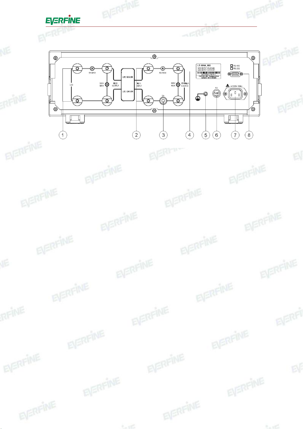
Fig.4.2 Rear Panel of LT-101A
○
1Output measuring terminal: Output terminal of LED driver and input terminal of
LED load when measuring output characteristic of LED driver.
○
2Input measuring terminal: Connect power supply and load when measuring input
characteristic of LED driver.
○
3Fuse holder: There is a fuse for input current under test, with the specification
250V/8A and the dimensionφ5×20mm.
○
4Nameplate: It is marked with type, ex-factory, maximum input voltage, maximum
input current, etc.
○
5Grounding terminal: For the safe of the users, the instrument should be well
grounded.
○
6Fuse holder: There is a fuse for the instrument inside it, with the specification
250V1A and dimensionφ5×20mm.
○
7Power: Socket for the instrument, the rated voltage is AC 220V/50Hz or
220V/60Hz.
○
8RS-232-C interface: To communicate with computer via this interface.
LT-101A User’s Manual
Copyright © EVERFINE, Copy or spread without authorization is prohibited. 15
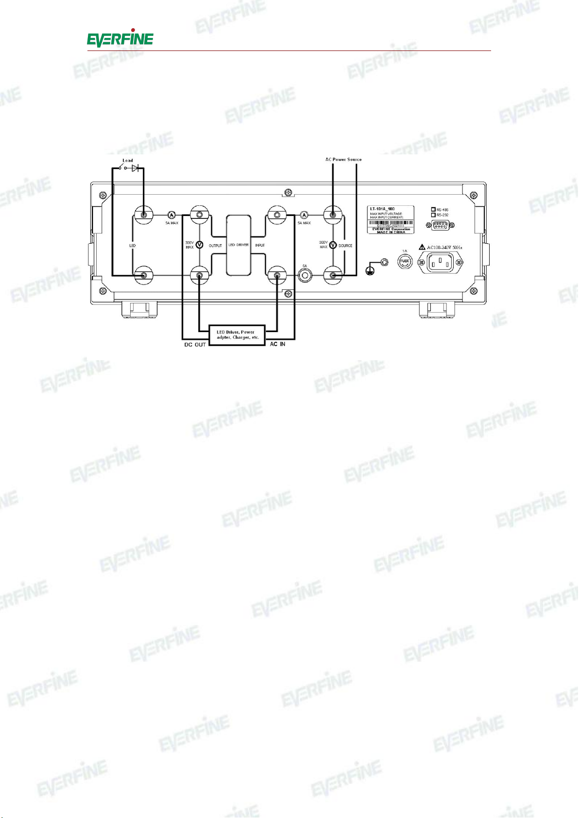
4.2 Measurement connections
Make sure that the power supply is in the range of the rated value, which is AC
220V.±22V, 50Hz/60Hz. The measurement connection is shown as Fig.4.3.
Fig.4.3 Measurement connections
To connect the measurement wires according to Fig.4.3.
Press power switch in front panel to turn on the instrument.
Please refer to Chapter 5 for the operation of setting and testing parameters.
If you need remote control, connect the RS232 interface (○
8of the Fig.4.2) in rear
panel with PC serial communicate interface, please refer to Chapter 6 for details.
When finishing the test, turn off the power supply for LED driver before turning off
the power switch on front panel, the instrument will stop working.
Note: The power supply for LED driver should be turned off before starting the
instrument.

LT-101A User’s Manual
Copyright © EVERFINE, Copy or spread without authorization is prohibited.
16
Chapter 5 Operations
5.1 Input characteristics test at steady state
5.1.1 Testing parameters
The input RMS values of voltage and current, active power, power factor, frequency,
total harmonic distortion of voltage and current, RMS and relative values of harmonic
from 0th to 50th can be measured.
5.1.2 Window display
During general test, window A displays RMS value of the voltage, window B displays
RMS value of the current, window C displays the active power, and window D can
display the power factor or the frequency according to the selection.
During harmonic analysis, window A displays the RMS or relative value (V%)of
harmonic voltage in different orders, window B displays the RMS or relative value
(A% )of harmonic current in different orders, window C displays order of the
harmonic or the total harmonic distortion (THD), and window D displays CSA or IEC
according to the selection.
Note: There are two formulas for the calculation of THD, which are IEC and CSA.
IEC method: THD=
%100
)(
1
2
2
C
C
n
k
k
CSA method: THD=
%100
)(
)(
1
2
2
2
n
k
k
n
k
k
C
C
where THD is the relative value of total harmonic distortion of voltage or current;

LT-101A User’s Manual
Copyright © EVERFINE, Copy or spread without authorization is prohibited. 17
C1is the RMS value of 1st harmonic;
Ckis the RMS value of kth harmonic;
k is the order of the harmonic;
n is the maximum order of the harmonic(For LT-101A, it is 50).
Notes: The range of input harmonic signal is 10% ~ 100% F.S..
5.1.3 Harmonic analysis
"ANALYZE": Press "ANALYZE", the indictor will be flickering and the instrument
is under the state of harmonic analyze, press again to exit.
"RMS": Press "RMS" to display the RMS or relative value of harmonic in different
times.
"" and"": Change the frequence of harmonic on window C.
5.2 Output characteristic test at steady state
5.2.1 Measurement parameters
The output electric parameters can be tested under stable state including RMS values
of voltage and current, frequency, active power, and power factor of power supply.
5.2.2 Window display
The output voltage(V) or frequency(Hz) can be displayed in Window E according to
different selection, and the output current(A) of LED driver can be displayed in
window F. In addition, the active power(W) or power factor(PF) can be displayed in
window G according to different selection and the efficiency of power supply can be
displayed in window H.
5.2.3 Steady-state testing
Press "RUNNING" to switch into the steady state from output start-up testing state.

LT-101A User’s Manual
Copyright © EVERFINE, Copy or spread without authorization is prohibited.
18
5.3 Start-up characteristic test
5.3.1 Measurement parameters
(1) Input: It can measure input peak values of voltage and current (impulsion) at
0~40ms when starting the LED driver. The test software can draw the curves of
voltage and current during this time, and calculate the start time according to related
standards and display it.
(2) Output: It can measure output peak RMS values of voltage and current, and the
time of current to get the maximum value at 0~3s when starting the LED driver. The
test software can draw the curves of voltage and current during this time.
Notes: Please pay attention to the difference between start-up time and the time being
displayed after the starting-up. The time being displayed by the instrument is the time
for current to get the maximum value, and start-up time is displayed by the test
software.
5.3.2 Start the start-up characteristic testing
Press "START" to start the start-up characteristic test when it is under the state of
"RUNNING" or "START".
Steps:
1. Press "START" to start the test;
2. If the load switch on front panel is on, input display window will display "PLEASE
TURN OFF" which prompts turning off the load switch. Or else go to step 4;
3. Turn off the load switch;
4. Input display window displays "PLEASE TURN ON", which prompts turning on
the load switch;
5. Turn on the load switch when LED lamp is cooled down;
6.It will sample for 3s when the output display window shows "PLEASE WAIT"
meanwhile the keys are invalid;
7. When " ---- ---- ---- ----" is displayed in output display window , it means there is
Table of contents
Popular Test Equipment manuals by other brands

Renishaw
Renishaw XM-60 multi-axis calibrator manual

D&V Electronics
D&V Electronics CDT-65A Operation manual

Keysight Technologies
Keysight Technologies N2142A quick start guide

Anritsu
Anritsu MT9812B Service manual

PEWA
PEWA Metrel MD 1100-LCD operating instructions

Agilent Technologies
Agilent Technologies InfiniiVision 5000 Series user guide


