Slaughter 6330 User manual
For Model: 6330
WARNING: THIS GUIDE WAS CREATED FOR OPERATORS HAVING SOME FAMILIARITY WITH
ELECTRICAL SAFETY TESTING. AN ELECTRICAL SAFETY TESTER PRODUCES VOLTAGES AND CURRENTS THAT
CAN CAUSE HARMFUL OR FATAL ELECTRIC SHOCK. TO PREVENT ACCIDENTAL INJURY OR DEATH, THESE
SAFETY PROCEDURES MUST BE STRICTLY OBSERVED WHEN HANDLING AND USING A TEST INSTRUMENT.
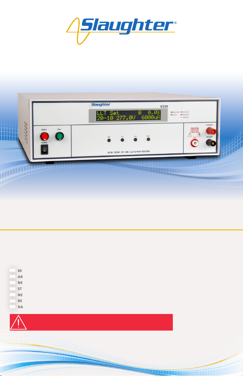
6330
6-in-1 Multi-Function
Electrical Safety Tester
Quick Start Guide
SAFETY CHECKLIST
KEEP unqualied/unauthorized personnel away from the test area
ARRANGE test staons in a safe and orderly manner
NEVER touch products or connecons during a test
STOP the test rst in the event of a problem
NEVER perform a Ground Bond test on energized circuitry or equipment
BE SURE to always connect the return test lead rst
HANDLE test clips by insulaon only, never touch clips directly
Safety Made Simple
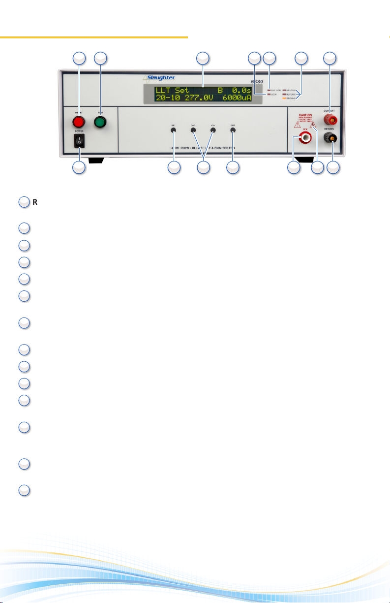
Front Panel Controls
1.
RESET BUTTON: Red momentary contact switch used to reset the instrument in case of a
failure. Also serves as an abort signal to stop any test in progress.
TEST BUTTON: Starts a test.
LCD DISPLAY: 20 x 2 character display.
LOCK INDICATOR: This LED indicates that the lock feature has been enabled.
BUS INTERFACE INDICATOR: This LED indicates that the bus interface has been enabled.
FAULT CONDITION INDICATORS: These LED’s indicate that the Neutral, Reverse, and
Ground line condions have been acvated during a Line Leakage test.
CURRENT OUTPUT TERMINAL: Used to aach the current test lead or test xture to the
instrument. Provides the high current output from the instrument.
POWER SWITCH: Rocker-style switch with internaonal ON ( | ) and OFF (0) markings.
SET KEY: Use this key to advance forward through the setup menus.
UP-DOWN ARROW KEYS: Use these keys to cycle through test parameter setup.
EXIT KEY: Use this key to exit any menu or to clear an unwanted entry in a
parameter eld.
HIGH VOLTAGE OUTPUT TERMINAL: Provides the high voltage used during a Hipot test.
Connector used to aach the high voltage test lead, adapter box high voltage lead or test
xture high voltage lead to the instrument.
HIGH VOLTAGE INDICATOR: This indicator ashes to warn the operator that high voltage
is present at the high voltage output terminal.
RETURN OUTPUT TERMINAL: Provides the return current path. Connector used to aach
the return test lead, adapter box return lead or test xture return lead to the instrument.
(6330 Front Panel)
10
10
11
11
12
12
13
13
14
14
2
2
3
3
4
4
5
5
6
6
7
7
8
8
9
9
1
1

Back Panel Controls
2.
(6330 Back Panel)
10
11
12
13
14
15
2
3
4
5
6
7
8
9
1EXTERNAL MEASURING DEVICE: Provides an access port for a custom measuring device. The
port may be acvated during Line Leakage tesng from the instrument’s menu system. The
operator must supply the appropriate measuring device as none is provided.
POWER CONTROL: N/A
FUSE RECEPTACLE: Fuse rang is 6.3 A at 250 VAC. To change the fuse, unplug the power (mains)
cord and turn the fuse receptacle counterclockwise. The fuse compartment will be exposed.
Please replace the fuse with one of the proper rang.
CALIBRATION BUTTON: To put the instrument into the calibraon mode push this buon and
turn on the power switch simultaneously.
SIGNAL INPUT: 9-pin D-type subminiature male connector for remote control of TEST, RESET,
AND INTERLOCK funcons as well as remote memory tests recall.
SIGNAL OUTPUT: 9-pin D-type subminiature female connector for monitoring PASS, FAIL, and
PROCESSING output relay signals.
BUS INTERFACE: Oponal connector for interconnecon to RS-232 bus interface.
DUT POWER INPUT: Provides the line and neutral connecons for an input power source to be
used during Funconal Run and Line Leakage tesng. Only a U.S. style single phase unbalanced
power source may be used.
DUT POWER OUTPUT: Provides the line and neutral connecons from the 6330 to the DUT during
Funconal Run and Line Leakage tesng. Provides the high voltage connecons to the DUT during
ACW, DCW and IR tesng if the DUT OUTPUT and DUT-HV parameters are turned ON.
GROUND CONNECTION: Connector used to aach the adapter box ground lead to the instrument.
CASE CONNECTION: Provides the return connecon during ACW, DCW or IR tesng. This
terminal is wired in parallel with the return terminal during a Ground Bond test and may be
used in place of the front panel connecon. During a Line Leakage test this connecon provides
a connecon to one side of the measuring device (MD).
CHASSIS GROUND (EARTH) TERMINAL: This safety terminal should be connected to a good
earth ground before operaon.
INPUT POWER RECEPTACLE: Standard IEC 320 connector for connecon to a standard NEMA
style line power (mains) cord.
VOLTAGE SELECT SWITCH: Sets the line voltage conguraon of the instrument. In the le
posion it is set for 115 volt operaon, in the right posion it is set for 230 volt operaon.
THERMAL FAN: Runs connuously to cool the instrument.
2 3 4 5 6 71
10 11 12 13 14 158 9
3.
Setting Up The Instrument
Editing System Parameters
WARNING: LOCATE A SUITABLE TESTING AREA WITH A THREE-PRONG, GROUNDED OUTLET. BE SURE
THAT THE THREE PRONG OUTLET HAS BEEN TESTED FOR PROPER WIRING. MAKE SURE YOU READ THE SAFETY
CHECKLIST OF THIS GUIDE BEFORE USING THE INSTRUMENT.
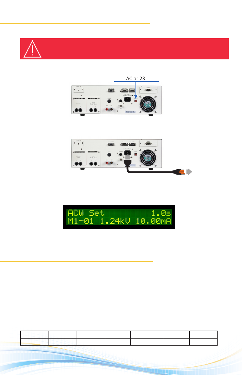
1. Adjust the line voltage select switch on the rear panel of the instrument to the
appropriate input voltage rang, either 115 VAC or 230 VAC.
2. Connect the female end of the standard NEMA style line power (mains) cord into the
input power receptacle on the rear panel of the instrument and plug the male end of
the cord into a grounded power source.
3. Turn the instrument power switch ON. Upon power up, you will see the Slaughter
Company name, Model Number, and current soware version briey appear on the
LCD display and then you will see the default test parameters as follows:
Congure the instrument system parameters to your preferences. The instrument
system parameters are global and will aect all tests that are performed regardless of
memory locaon and memory step.
1. Press EXIT from the Perform Test screen to edit the system parameters.
2. Press the SET key to toggle through the parameters and use the up or down arrow
keys to edit the parameters.
Default system parameters shown below:
(Perform Test Screen)
To Grounded
Power Source
PLC Remote Single Step Fail Stop Lock Memory Lock Alarm DUT-HV Set
OFF OFF OFF OFF OFF 5 ON

4.
Editing Test Parameters
Selecting A Memory Location
If you wish to change the default test sengs, you will need to begin by choosing a
memory locaon rst.
There are 20 memory locaons each of which contains 10 steps. The steps can be
connected sequenally to form a mul-step test roune. Only one electrical safety test type
can be selected for each step. In order to connect a step, the “Connect” parameter needs
to be turned ON.
1. Press the SET key from the Perform Test screen to select a memory locaon. Use the up
or down arrow keys to select memory locaons 1 – 20.
2. Press the SET key again to select the step. Use the up or down arrow keys to cycle
through steps 1-10.
3. Press the EXIT key to store changes and return to the Perform Test screen.
Now that the memory locaon has been set up, you may now congure your test roune.
1. Press the SET key from the Perform Test screen to conrm the memory locaon.
2. Press the SET key again to conrm the memory step number. You should start by
modifying step 1.
3. Press the SET key a third me unl one of the following test types appear:
4. Use the up and down arrow keys to toggle the test type between ACW, DCW, IR, GND,
RUN, and LLT.
5. Press the EXIT key to save the seng and return to the Perform Test screen OR press
the SET key to toggle between the parameters for the selected test type.
6. Use the up or down arrow keys to edit each test parameter.
7. When you are nished eding the test parameters press the EXIT key to save your
sengs and return to the Perform Test screen.
Default test type parameters are shown on next page.
Memory Locaon Memory Step Number

5.
Editing Test Parameters
Default test type parameters are shown below.
There are a total of 8 dierent Line condions that may be congured. They are displayed
in the following table:
AC Hipot Mode
• Voltage: 1.24 kV
• HI-Limit: 10.00 mA
• Lo-Limit: 0.00 mA
• Ramp: 0.1 s
• Dwell: 1.0 s
• Frequency: 60 Hz
• Arc Detect: OFF
• Arc Sense: 5
• DUT Output: On
• Connect: O
Funconal Run
• Volt-Hi: 125.0 V
• Volt-Lo: 0.0 V
• Amp-Hi: 10.0 A
• Amp-Lo: 0.0 A
• Power-Hi: 1000 W
• Power-Lo: 0 W
• PF-Hi: 1.000
• PF-Lo: 0.000
• Leakage-Hi: 10.00 mA
• Leakage-Lo: 0.00 mA
• Delay: 0.2 s
• Dwell: 1.0 s
• Connect: O
DC Hipot Mode
• Voltage: 1.50 kV
• HI-Limit: 5.00 mA
• Lo-Limit: 0.00 mA
• Ramp: 0.1 s
• Dwell: 1.0 s
• Arc Detect: OFF
• Arc Sense: 5
• DUT Output: On
• Connect: O
Line Leakage Mode
• Volt-Hi: 125.0 V
• Volt-Lo: 0.0 V
• Leakage-Hi: 6000 µA
• Leakage-Lo: 0.00 µA
• Line: 7
• MD: MD A
• Probe: G-L
• Delay: 1.0 s
• Connect: OFF
Insulaon Resistance
• Voltage: 500 V
• HI-Limit: 0 mΩ
• Lo-Limit: 1 mΩ
• Delay: 1.0 s
• DUT Output: On
• Connect: O
Ground Bond Test
• Current: 30 Amps
• HI-Limit: 100 mΩ
• Lo-Limit: 0 mΩ
• Dwell: 1.0 s
• Oset: 0 mΩ
• Frequency: 60 Hz
• Connect: O
Line 12345678
Neutral OPEN OPEN OPEN OPEN CLOSE CLOSE CLOSE CLOSE
Reverse OFF ON OFF ON OFF ON OFF ON
Ground OPEN OPEN CLOSE CLOSE OPEN OPEN CLOSE CLOSE

6.
Adapter Box Connecons
The adapter box may be used for products that are terminated in either a two prong or
three prong line cord. It is easy to use the adapter box for all six test funcons.
See back page for diagram.
1. Remove the cover plate on the rear panel of the 6330 to access the DUT Output
Connecons. These connecons provide power to the DUT during a Line Leakage or
Funconal Run test.
2. Connect the adapter box (P/N 99-10467-01) to the DUT Output L (line), N (neutral)
terminals, and the ground terminal.
3. Aach the black case lead (P/N 99-10457-01) to the case terminal and connect the
ground return clip to the dead metal on the chassis of the DUT.
4. Plug the line cord from the DUT into the adapter box receptacle (P/N 99-10467-01).
The adapter box will now provide power to the DUT during Funconal Run and Line
Leakage tesng.
Test Connections
DUT Power Input Connecons
Remove the cover plate on the rear panel of the 6330 to access the DUT Power Input
Connecons. These terminals provide the connecons from an external power source to
the 6330. See back page for diagram.
5. Use the black 10 AWG cables (P/N 99-10469-01 & 99-10470-01) to connect to an
unbalanced, single-phase power source for applicaons not exceeding 30 amps.
Note: The 220 - 240 volt U.S. style line power cord is NOT suitable to connect to the DUT
inputs. This style of power distribuon is a balanced type with two HOT or LINE conductors.
If voltage is applied to pin 2, N (neutral) terminal of the DUT Power Input and you aempt
to execute a Run test or Line Leakage test, a warning will appear on the screen that says
Neutral-V.
If this message appears, the voltage problem will need to be corrected before the
instrument allows you to execute Funconal Run or Line Leakage tests.
WARNING: BE SURE THAT THE HOT LEAD OF THE POWER SOURCE IS CONNECTED TO PIN 1,
(LINE) TERMINAL OF THE DUT POWER INPUT TERMINAL BLOCK AND THE RETURN OR LOW VOLTAGE
LEAD IS CONNECTED TO PIN 2, N (NEUTRAL) TERMINAL OF THE DUT POWER INPUT TERMINAL BLOCK.
DO NOT CONNECT A LINE CONDUCTOR TO THE N OR NEUTRAL TERMINAL OF THE DUT POWER INPUT.
THIS CONDITION CAN BE VERY DANGEROUS TO THE OPERATOR.

6330-3/13
www.hipot.com Toll Free (800) 504-0055 or (847) 932-3662
© 2013 Slaughter Company, Inc.
Scan the QR code
to get further
support or visit
www.hipot.com
Safety Made Simple
View test results by pressing the up and down arrow keys from the Perform Test screen.
PASS: If the DUT passes the test, you will hear a short audible beep and the display will
indicate the test results.
FAIL: If a failure occurs, you will hear a long audible alarm and the red ashing indicator
will light up. To stop the alarm press the red RESET buon.
(PASS/FAIL Indicaon Screen)
CAUTION: THE ADAPTER BOX (P/N 99-10467-01) MAY BE USED TO PERFORM HIPOT, GROUND BOND,
INSULATION RESISTANCE, FUNCTIONAL RUN, AND LINE LEAKAGE TESTS. THE ADAPTER BOX IS RATED FOR A
MAXIMUM OF 20 AMPS OF INPUT CURRENT. IF CURRENT LEVELS GREATER THAN 20 AMPS ARE NEEDED FOR
EITHER THE FUNCTIONAL RUN TEST OR THE LINE LEAKAGE TEST, THE STAND ALONE TEST LEADS MUST BE USED.
Test Connections
Test Results
DUT POWER INPUT
NL
GND CASE
DUT OUTPUT
CAUTION
HIGH VOLTAGE
5KVAC MAX.
6KVDC MAX.
1.
2.
3.
4.
5.
Other manuals for 6330
1
Table of contents
Other Slaughter Test Equipment manuals


Popular Test Equipment manuals by other brands


Hioki
Hioki MEMORY HiCORDER 8855 instruction manual

Seaward
Seaward 227A910 Operation instructions

Keysight Technologies
Keysight Technologies Infiniium 90000A Series Service guide

HP
HP 54501A Programming reference

Gossen MetraWatt
Gossen MetraWatt METRATESTER 5+ operating instructions

HP
HP 608E Operating and service manual


