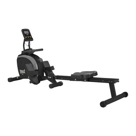
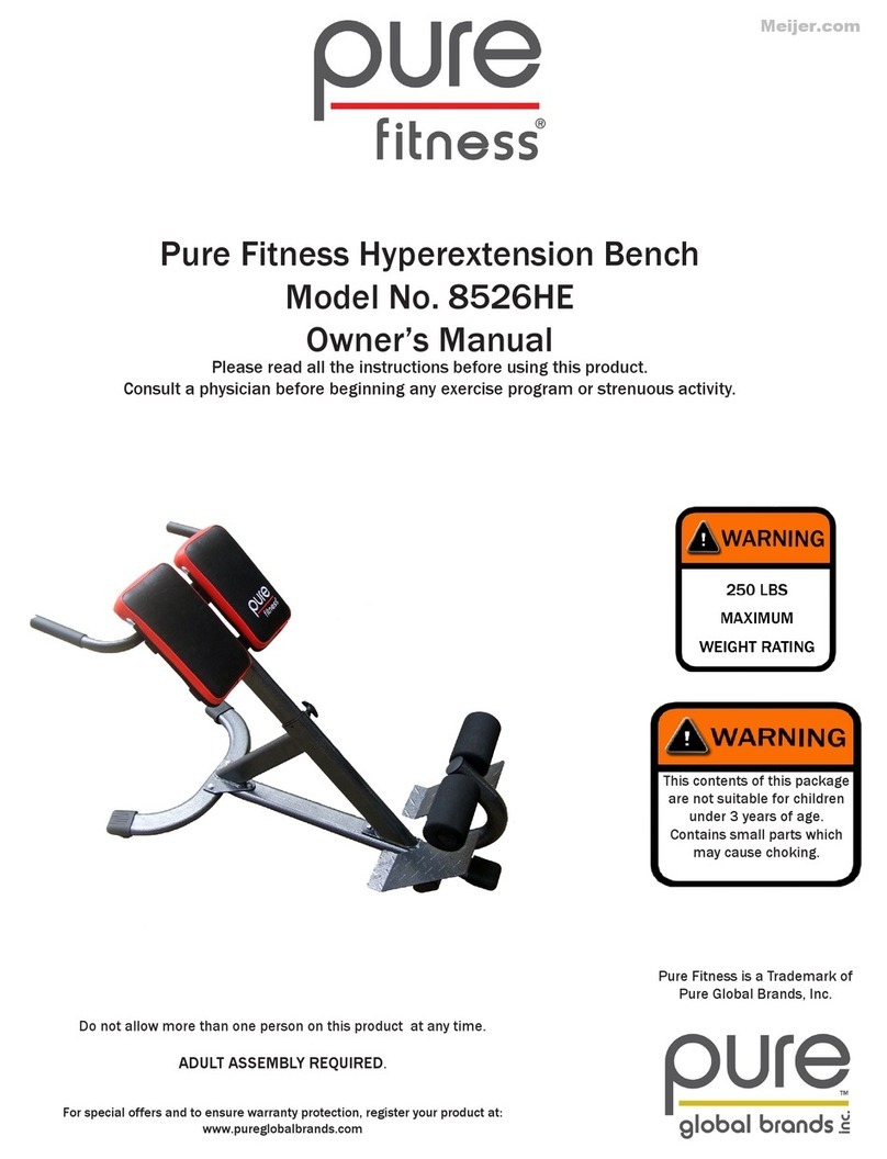
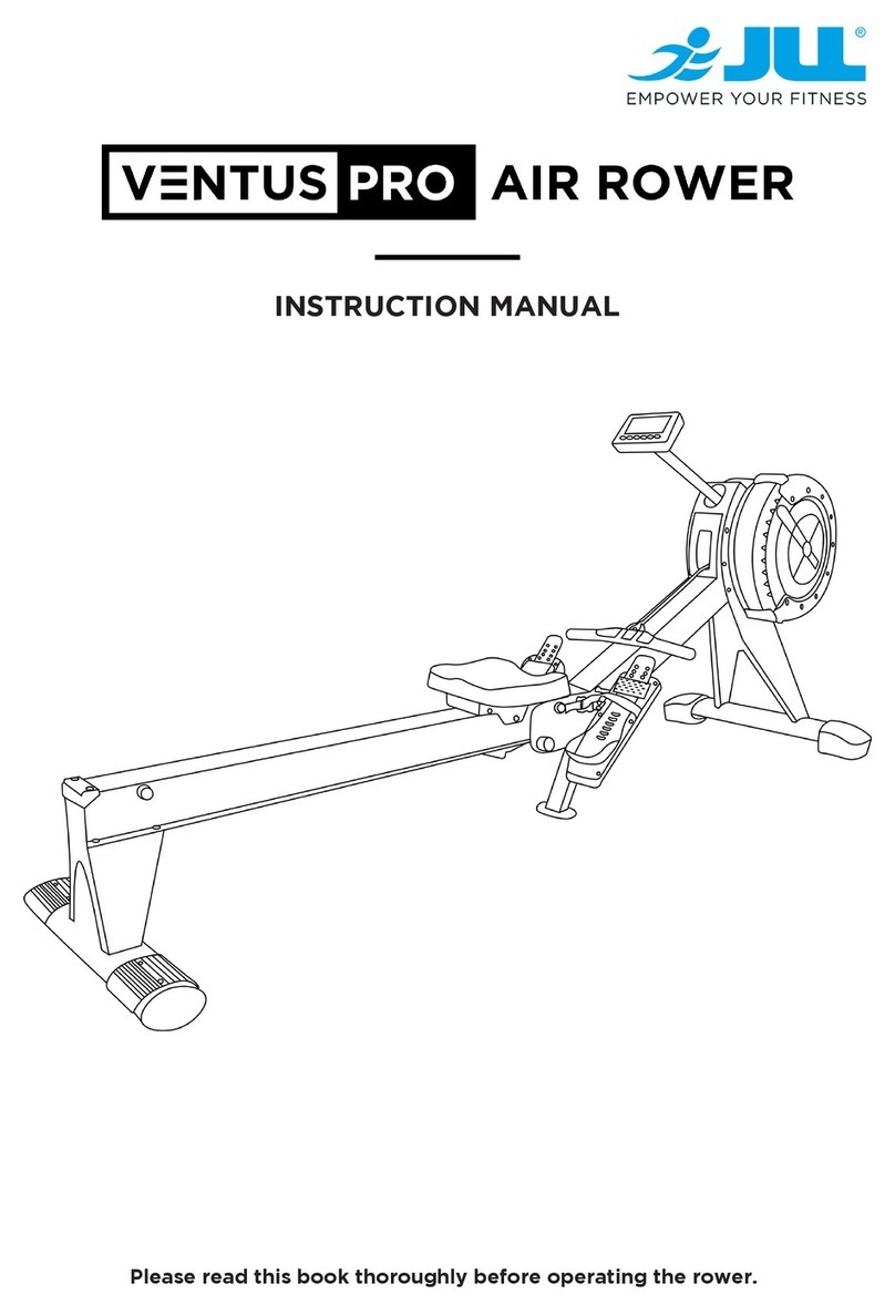
Everlast 16805539960 User manual

Retain for
Future reference
CAUTION:
You must read and understand this owner’s manual before operating unit.
OWNER`S
MANUAL
Model No.
16805539960
Everlast
Rower
Assembly
Operation
Exercise
Parts
Warranty

Customer Service 1-888-707-1880
Or email customerservice@dyaco.ca Dyaco Canada Inc.© 2015
- 1 -
TABLE OF CONTENTS
Manufacturer’s Limited Warranty……………………..……....
2
Safety Precautions…………………………………….…..…....
3-4
Hardware Packing List.…………………………………..…….
5
Pre-assembly Check List……………………………..……..…
6
Assembly Instruction……………………….………………..….
7-12
Monitor Instruction………………………...…………………….
13-15
Using Heart Rate Transmitter (Optional)……………………..
16
Part List / Diagram………………………………………………
17-21
How to Row………………………………………………………
22
Trouble Shooting…………………………….……...…………..
23
Training Guideline………………………………….……………
24-26
Stretching…………………………………………..…………….
27-28
Dyaco Brand……………………………………………………..
29

Customer Service 1-888-707-1880
Or email customerservice@dyaco.ca Dyaco Canada Inc.© 2015
- 2 -
MANUFACTURE’S ONE-YEAR LIMITED WARRANTY
Your Everlast is warranted for one year from the date of purchase against defects in material,
when used for the purpose intended, under normal conditions, and provided is receives proper
care. Any part found defective or missing will be sent at no cost when returned in accordance with
the terms of this warranty.
Home Use Limited WARRANTY
Frame 2 Years
All Other Components 1 Year
Labour 1 Year
This warranty is not transferable and is extended only to the original owner.
The warranty shall not apply to rowing machines which are (1) used for commercial or other
income producing purposes, or (2) subject to misuse, neglect, accident or unauthorized repairs
and alterations.
This warranty provided herein is in lieu of all other express warranties. Any implied warranties,
including any implied warranties of merchantability or fitness for particular purpose, are limited in
duration to the first 12 months from the date of purchase.All other obligations or liabilities,
including liability for consequential damages, are hereby excluded.
REPAIR PARTS AND SERVICE
All of the parts for the rowing machine, shown in figure can be ordered from Dyaco Canada Inc. 6050 DON
MURIE STREET, NIAGARA FALLS, ONTARIO L2G 0B3. When ordering parts, the parts will be sent and billed
at the current prices. Prices may be subject to change without notice. Check or money order must accompany
all orders. Standard hardware items are available at your local hardware store.
To ensure prompt and correct handling of any errors, or to answer any questions, please call our
Toll Free number: 1-888-707-1880, or local number 1-905-353-8955 or fax 1-905-353-8968 or
to 5:00 PM Monday to Friday Eastern Standard Time.
Always include the following information when ordering parts
Model Number
Name of Each Part
Part Number of Each Part

Customer Service 1-888-707-1880
Or email customerservice@dyaco.ca Dyaco Canada Inc.© 2015
- 3 -
SAFETY PRECAUTIONS
Thank you for purchasing our product. Even though we go to great efforts to ensure the quality of
each product we produce, occasional errors and /or omissions do occur. In any event should you
find this product to have either a defective or a missing part please contact us for a replacement.
This product has been designed for home use only. Product liability and guarantee conditions will
not be applicable to products being subjected to professional use or products being used in a gym
center.
This exercise equipment was designed and built for optimum safety. However, certain precautions
apply whenever you operate a piece of exercise equipment. Be sure to read the entire manual
before assembly and operation of this machine. Also, please note the following safety
precautions:
1. Read the OWNER’S OPERATING MANUAL and all accompanying literature and follow it
carefully before using your rowing machine.
2. If dizziness, nausea, chest pains, or any other abnormal symptoms are experienced while
using this while using this equipment, STOP the workout at once. CONSULTA PHYSICIAN
IMMEDIATELY.
3. Inspect your exercise equipment prior to exercising to ensure that all nuts and bolts are fully
tightened before each use.
4. The rowing machine must be regularly checked for signs of wear and damage. Any part found
defective must be replaced with a new part from the manufacturer.
5. Fitness equipment must always be installed on a flat surface, It is recommended to use an
equipment mat to prevent the unit from moving while it is being used, which could possibly
scratch or damage the surface of your floor.
6. No changes must be made which might compromise the safety of the equipment.
7. It is recommended to have a minimum of 2’ safe clearance around the exercise equipment
while in use.
8. Ensure that the rail is locked properly when in storage.
9. Do not allow children to use or play on the rower. Keep children and pets away from this
equipment at all times while exercising.
10. The rower should only be used by one person at a time.
11. Maximum user weight 300lbs (136KG).
12. Warm up 5 to 10 minutes before each workout and cool down 5 to 10 minutes afterward.
This allows your heart rate to gradually increase and decrease and will help prevent you
from straining muscles.
13. Never hold your breath while exercising. Breathing should remain at a normal rate in
conjunction with the level of exercise being performed .
14. Always wear suitable clothing and footwear while exercising. Do not wear loose fitting
clothing that could become entangled with the moving parts of your rowing machine. Do not
exercise in bear feet or socks. Proper footwear such as running, walking or cross training
shoes should be worn.
15. Tie all long hair back. Remove all personal jewelry before exercising
16. Be careful to maintain your balance while using, mounting, dismounting the rower, loss of
balance may result in a fall and bodily injuries.
17. After eating, allow 1-2 hours before exercising as this will help to prevent muscle strain.
18. Injuries may result from incorrect or excessive training and using the equipment otherwise
than as directed or recommended by your doctor.
Customer Service 1-888-707-1880
Or email customerservice@dyaco.ca Dyaco Canada Inc.© 2015
- 4 -
19. Care must be taken when lifting or moving the equipment, so as not to injure your back.
Always use proper lifting techniques
20. Do not use the seat to move the Everlast Rower. The seat will move and the seat carriage
may pinch your hands or fingers. When folding or unfolding the unit, keep all children away
and make sure hands are clear of any folding or pinch point.
21. Before using, check the condition of the strap. Replace the strap attached to the spring box if
it is cracked or broken.
WARNING: BEFORE BEGINNING ANY EXERCISE PROGRAM CONSULT YOUR
PHYSICIAN. THIS IS ESPECIALLY IMPORTANT FOR INDIVIDUALS OVER THE AGE OF 35
OR PERSONS WITH PRE-EXISTING HEALTH PROBLEMS. READ ALL INSTRUCTIONS
BEFORE USING ANY FITNESS EQUIPMENT. WE ASSUME NO RESPONSIBILITY FOR
PEROSNAL INJURY OR PROPERTY DAMAGE SUSTAINS BY OR THROUGH THE USE OF
THIS PRODUCT.
SAVE THESE INSTRUCTIONS

Customer Service 1-888-707-1880
Or email customerservice@dyaco.ca Dyaco Canada Inc.© 2015
- 5 -
HARDWARE PACKING LIST
PART
DESCRIPTION
Q’TY
SKETCH
21
Seat track end cap
1
23
Spacer
1
24
Knob
1
26
Flat washer M8
6
29
Cap nut M10
4
76
Nylon nut M10
4
77
Flat washer M10
8
104
Spring washer M8
4
110
Round head bolt M8x25mm
2
78
Flat washer M8
4
114
Spring washer M10
8
117
Allen head bolt M8x15mm
8
122
Nut M8
1
123
Hex head bolt M8*85mm
1
22
Seat Carriage Stopper
2
111
Pin
1
107
M10x25 Allen head bolt
4
144
Allen wrench
2
145
Universal wrench
1
Note: Above parts are all the parts needed to assemble this machine. Before you start to assemble,
please check the hardware packing to make sure they are included.

Customer Service 1-888-707-1880
Or email customerservice@dyaco.ca Dyaco Canada Inc.© 2015
- 6 -
PRE-ASSEMBLY CHECK LIST
PART NO.
DESCRIPTION
QTY
1
Front frame with air mag. drive system set
1
6/28(R/L)/124
Front stabilizer w/transportation wheels, anti-slippery pads
1
5/20(R(L)/98
Rear stabilizer w/end caps, level knobs
1
12/7/113(R/L)/125
Foot plate w/foot pedal, pedal straps, elastic velcro straps
1P
4/3/120
Seat track w/connected bracket, count sensor wire
1
13/8/17
Seat w/carriage wheel set
1
84/83
Monitor w/four screws
1
2/105/122/27
U support bracket w/knob, spacer, level knob
1
138
Wireless chest belt set
1
116
Adaptor with cable
1
1
6/28(R/L)/124
5/20/98
7/12/113(R/L)125
2/27/105/122
83/84
138 116
4
13/8

Customer Service 1-888-707-1880
Or email customerservice@dyaco.ca Dyaco Canada Inc.© 2015
- 7 -
ASSEMBLY INSTRUCTION
This manual is designed to help you easily assemble, adjust and use this machine. Please read
this manual carefully. For the sake of familiarizing yourself with the parts identified in the
instruction, first study the overview drawing.
Set all parts in a clear area on the floor and remove the packing material. Refer to the parts list for
help to identify the parts. It will take two people to assemble your unit.
It will take two people to assemble your unit.
Note: If a part is not in the hardware kit, check to see if it has been preassembled. To avoid
damaging parts, do not use power tools for assembly.
STEP 1
1) Cut the zip tie (82) between handlebar (65) and monitor support bracket (9).
3) Pull and slide the handlebar (65) and pass through the monitor support bracket (9) and
monitor bracket (11) carefully as shown.
4) Rotate the handlebar (65) to right 90∘and rest onto the handlebar stand (86) in position.
NOTE: Please follow the following step to assemble handlebar and avoid the chain to
drop off from the pivot shaft.
Use left hand to hold the chain (66) which is located on gear of pivot shaft and right hand
grips handlebar (65) through the monitor support bracket (9) & monitor bracket (11),
and place handlebar (65) on stand (86).
5) Put the top welded bracket of front stabilizer (6) with two wheel caps (28R/L) to bottom
four screw holes of front main frame (1) and tighten with four cap nuts (29), four spring
washers (114) and four flat washers (77).
6) Attach “U”support bracket (2) to the end “U”welded bracket of front main frame (1) and
tighten with two allen head bolts (107), two flat washers (77), two spring washers (114)
and two nylon nuts (76).
NOTE: After finish whole product assembly, you can screw the pre-assembled level knob
(27) to adjust the whole product balance.
65
1
1
2
9
82
1
29
77
114
1
6
107
11476
107 77
2
3105
65
86
9
11
27
2

Customer Service 1-888-707-1880
Or email customerservice@dyaco.ca Dyaco Canada Inc.© 2015
- 8 -
STEP 2
1) Slide the seat (13) with seat carriage set (8) into the rower seat track (4) which direction is
from end of seat track (4).
2) Put one bolt (123) with one stopper (22) through the two side hole of rower seat track (4)
and tighten with another stopper (22) and nut (122).
3) Put the end cap (21) into end of seat track (4).
4
13
122
22
22
123
21
8
STEP 3
1) Attach the welded bracket of rear stabilizer (5) with two end cap sets (20/98) to the bottom
screw hole of end seat track (4) and tighten with four allen head bolts (117), four spring
washers (104) and four flat washers (26).
NOTE: After finish whole product assembly, you can screw the pre-assembled level knob
(98) of rear stabilizer (5) to adjust the whole product balance.
5
26
104
117
4
98
20

Customer Service 1-888-707-1880
Or email customerservice@dyaco.ca Dyaco Canada Inc.© 2015
- 9 -
STEP 4
1) Connect the socket of count sensor wire (120) of seat track (4) to the plug of count sensor
wire (129) of front main frame (1).
2) Attach front connected bracket (3) of seat track (4) to the “U”shape welded bracket of
front main frame (1) and tighten with round head bolts (110) and flat washers (26) on two
side of U shape bracket.
3) Put the knob (24) with big spacer (23) to the bottom screw hole of front end seat track
(4) and secure with level knob (24) till touching the "U”welded bracket.
NOTE: Avoid punching all cables and wires.
4) Screw the pre-assembled knob (105) to let the bottom knob (27) to touch the ground.
110
26
26
110 120
1
3
2
1
4
24
23
129
105 27

Customer Service 1-888-707-1880
Or email customerservice@dyaco.ca Dyaco Canada Inc.© 2015
- 10 -
STEP 5
1) Put white pivot shaft (75) through the upper welded sleeve tube of U support bracket (2).
2) Put black pivot shaft (109) through the lower welded sleeve tube of U support bracket (2).
3) Attach right side foot plate (7) with foot pedal (12) which is pre-assembled with elastic velcro
straps (125) and right pedal straps (113R) to the two pivot shaft (75/109) and tighten them with
two washers (78) and two bolts (117).
4) Do the same procedure to assemble left side foot plate (7) with foot pedal (12), elastic velcro
straps (125) and left pedal straps (113L).
NOTE: Please use 6 set hole position of foot pedal (12) to adjust user’s foot size.
78
78
117
117
78
117
78
117
75
109
7R
7L
(BLACK)
(WHITE)
12
12 2
113L
125
125
113R

Customer Service 1-888-707-1880
Or email customerservice@dyaco.ca Dyaco Canada Inc.© 2015
- 11 -
STEP 6
1) Remove the pre-assembled four screws (83) from back of monitor (84).
2) Insert plug of system wire cable (102) to the socket of monitor (84).
3) Attach monitor (84) to the top adjustable monitor bracket (11) and tighten with previously
removed four screws (83) again.
NOTE: The manufacturer has pre-assembled the adjustable monitor bracket (11) with
monitor support bracket (9) on front main frame (1).
STEP 7
Insert the plug of the adaptor (116) into the socket (115) of power supply cable as shown.
Plug the two pin of adaptor (116) into the wall power supply.
84
83
102
11
9
ADJUST
12
ADJUST KNOB
ADJUST KNOB
98
98
ADJUST KNOB
105
12
116
115

Customer Service 1-888-707-1880
Or email customerservice@dyaco.ca Dyaco Canada Inc.© 2015
- 12 -
Now the rower is assembled completely.
HOW TO STORE YOUR ROWER
1) Loosen knob (24) with spacer (23) to leave 20mm distance and slide seat (13) to the front
end of seat track (4).
2) Push the two monitor support bracket (11) with monitor (84) forward a little bit to front main
frame (1).
3) Lift up seat track (4) to welded U bracket of front main frame (1) and insert the pin (111) to
thread the two side hole of “U“shape bracket of from main frame (1) and ear of front end
connected bracket (3) of seat track (4).
6
5
3
2
1
6
5
3
2
3
4
5
24
23
4
1
84
111
2
1
111
2
111
324
123
6
2
1
1
2

Customer Service 1-888-707-1880
Or email customerservice@dyaco.ca Dyaco Canada Inc.© 2015
- 13 -
MONITOR INSTRUCTION
QUICK START:
1. Press “display mode” button and then press “set” button until time is flashing to enter the “time” mode.
2. Begin rowing.
3. Adjust the resistance level with the “+”/ “-‘key
4. The values of time, distance, calories, count, will start counting upwards.
DISPLAY AND FEEDBACK:
AGE
The user age has been set.
PROGRAM
The number of the selected pre-set program (1~8).
min. iiiiiiiii max.
Displays the resistance level in manual mode.
THR
Target heart rate frequency has been set.
SCAN
Automatically scans through the feedback modes. Each being displayed for 5 seconds.
PULSE
Current heart rate in beats per minute (bpm) (Only displayed when the transmitter chest
strap is used.)
CAL
Approximate calories burned this session (for comparison only, not to be used for medical
purposes); default counts up from zero, but counts down if a target has been set.
SPM
The strokes per minute (S.P.M) you are rowing at.
DST
Distance travelled this session; default counts up from zero, but counts down if a target
has been set.
SPD
The current speed you are rowing at, in KM/H.
ODO
Total distance travelled since last battery changed.
TIME
Time exercised this session; default counts up from zero, but counts down if a target has
been set.
COUNT
Stroke exercised this session; default counts up from zero, but counts down if a target has
been set
500M
Expected exercise time for 500 meters travelled.
POWER
The force of each rowing stroke.
6
AGE
PROGRAM
SCAN
min max POWER
0
2
4
8
10
THR
PULSE CAL SPM RPM DST SPD ODO TIME COUNT 500M
KM/H

Customer Service 1-888-707-1880
Or email customerservice@dyaco.ca Dyaco Canada Inc.© 2015
- 14 -
BUTTON FUNCTIONS:
Button
Pre-workout
During workout
Display
Mode
Switch different mode values
Select display mode
Program
Press repeatedly to select a program (p1~p8)
set
Confirm current target values setting
reset
Reset current setting value, press & hold total reset
+
Increase values setting in “target setting”mode
Increase the resistance level
-
Decrease values setting in “target setting”mode
Decrease the resistance level
USING WORKOUT PROGRAMS:
When you turn the rower on it will enter the main display mode, waiting for your to select a program and
begin your workout.
MANUAL:
In manual mode, the user is free to adjust the resistance level at any point throughout the workout.
1. Press “program’button to choose your program (p1).
2. Press ”set”button to confirm the “manual”selection.
3. Start rowing to begin your workout.
NOTE: You can also add to your program targets based on time, distance, calories, stroke or pulse
rate. To do this, see the “Target Program”instruction below.
PROGRAM:
There are 5 pre-set programs available for you to choose from. The resistance level adjusts
automatically throughout the program.
1. Press “program”button to choose your program (P2~P6).
2. Press “set”button to confirm your selection
3. Press “display mode”button and then press “set”button until time is flashing to enter the
“time”mode.
4. The value of “00:00”will be flashing in the “time”window
5. Press “+”or “-“button to set your workout time
6. Press ‘set”to confirm your setting
7. Start rowing to begin your workout
NOTE: 1) You can change the resistance level at any point during the workout and the rest of
segments will be adjusted by scale automatically
2) You can also add to your program targets based on time, distance, calories, stroke or
pulse rate. To do this, see the “Target Program” instruction below
3) Each program is made up of 16 segments and the length of each segment will depend
on the time you set for your workout.

Customer Service 1-888-707-1880
Or email customerservice@dyaco.ca Dyaco Canada Inc.© 2015
- 15 -
H.R.C. (Heart Rate Control):
HRC program works by automatically adjusting the resistance to keep you working out at your target
heart rate. To do this the console will need your pulse reading throughout the exercise, which it gets
from you wearing a chest strap transmitter.
If your heart rate is too high the resistance is decreased.
If your heart rate is too low the resistance is increased
This console features 2 heart rate control programs:.
. 60% - Target to operate at 60% of your maximum heart rate to lose weight.
. 85% - Target to operate at 85% of your maximum heart rate to improve your stamina.
1. Press & hold“display mode’button for 5 seconds to enter the “age”mode
2. Press “+”or “-“button to set your age
3. Press “display mode’to confirm your setting
4. Press “program”button to choose your program (p7 –60% Max. HR/p8 –85% Max. HR)
5. Press “set”button to confirm your selection
6. The value of “THR”will be flashing in the “pulse”window
7. Press “set”to confirm your target heart rate setting
8. Start rowing to begin your workout
NOTE: You can also add to your program targets based on time, distance, calories or stroke. To do
this, see the “Target Program”instruction below
TARGET PROGRAM:
You can choose to workout by setting a target based on pulse rate, calories burned, distance travelled,
time or the strokes rowed you want to achieve.
When you reach your target the rower will sound a short alarm.
Set to your desired program as described previously, but before pressing “set”to begin your exercise.
1. The value of “0”will be flashing in the “pulse’window
2. Press “+’or “-“button to set your Target Pulse Rate.
3. Press “set’to confirm your setting
4. The value of “0”will be flashing in the “calories”window
5. Press “+”or “-“button to set your Target Calories
6. Press “set”to confirm your setting
7. The value of “0”will be flashing in the “distance”window
8. Press “+”or “-“button to set your Target Distance
9. Press “set”to confirm your setting
10. The value of “00:00”will be flashing in the “time”window
11. Press “+”or “-“button to set your Target Time
12. Press “set”to confirm your setting
13. The value of “0”will be flashing in the “count”window
14. Press “+”or “-“button to set your Target Stroke
15. Press “set”to confirm your setting
16. Start rowing to begin your workout
NOTE: You only have to set one of the targets described above, and once done you can press “set”
to go straight into your workout, however, if you set multiple targets the workout will end when
the first target is reached.

Customer Service 1-888-707-1880
Or email customerservice@dyaco.ca Dyaco Canada Inc.© 2015
- 16 -
USING
HEART
RATE
TRANSMITTER
(Optional)
How
to
wear
your
wireless
chest
strap
transmitter:
1.
Attach
the
transmitter
to
the
elastic
strap
using
the
locking
parts.
2.
Adjust
the
strap
as
tightly
as
possible
as
long
as
the
strap
is
not
too
tight
to
remain
comfortable.
3.
Position
the
transmitter
with
the
centered
in
the
middle
of
your
body
facing
away
from
your
chest
(some
people
must
position
the
transmitter slightly left of center). Attach the final end of the elastic
strap
by
inserting
the
round
end
and,
using
the
locking
parts,
secure
the
transmitter
and
strap
around
your
chest.
4.
Position
the
transmitter
immediately
below
the
pectoral
muscles.
5.
Sweat
is
the
best
conductor
to
measure
very
minute
heart
beat
electrical
signals.
However,
plain
water
can
also
be
used
to
pre-wet
the
electrodes
(2
ribbed
oval
areas
on
the
reverse
side
of
the
belt
and
both
sides
of
the
transmitter).
It’s
also
recommended
that
you
wear
the
transmitter
strap
a
few
minutes
before
your
work
out.
Some
users,
because
of
body
chemistry,
have
a
more
difficult
time
in
achieving
a
strong,
steady
signal
at
the
beginning.
After
“warming
up”,
this
problem
lessens.
As
noted,
wearing
clothing
over
the
transmitter/strap
doesn’t
affect
performance.
6.
Your
workout
must
be
within
range
-
distance
between
transmitter/receiver
–
to
achieve
a
strong
steady
signal.
The
length
of
range
may
vary
somewhat
but
generally
stay
close
enough
to
the
console
to
maintain
good,
strong,
reliable
readings.
Wearing
the
transmitter
immediately
against
bare
skin
assures
you
of
proper
operation.
If
you
wish,
you
may
wear
the
transmitter
over
a
shirt.
To
do
so,
moisten
the
areas
of
the
shirt
that
the
electrodes
will
rest
upon.
Note
: The
transmitter
is
automatically
activated
when
it
detects
activity
from
the
user’s
heart.
Additionally,
it
automatically
deactivates
when
it
does
not
receive
any
activity.
Although
the
transmitter
is
water
resistant,
moisture
can
have
the
effect
of
creating
false
signals,
so
you
should take
precautions
to
completely
dry
the
transmitter
after
use
to
prolong
battery
life
(estimated transmitter
battery
life
is
2500
hours).
The
replacement
battery
is
Panasonic
CR2032.
ERRATIC
OPERATION
Caution!
Do
not
use
this
rower
for
Heart
Rate
unless
a
sdy,
solid
Actual
Heart
Rate
value
is
being
displayed.
High,
wild,
random
numbers
being
displayed
indicate
a
problem.
Areas
to
look
for
interference
which
may
cause
erratic
heart
rate:
1.
Microwave
ovens,
TV’s,
small
appliances,
etc.
2.
Fluorescent
lights.
3.
Some
household
security
systems.
4.
Perimeter
fence
for
a
pet.
5.
Some
people
have
problems
with
the
transmitter
picking
up
a
signal
from
their
skin.
If
you
have problems
try
wearing
the
transmitter
upside
down.
Normally
the
transmitter
will
be
oriented
so
the
is right
side
up.
6. The antenna
that
picks
up
your
heart
rate
is
very
sensitive.
If
there
is
an
outside
noise
source, turning
the
whole
machine
90
degrees
may
de-tune
the
interference.
7.
Loose
treadmill
console
or
bolts
in
the
upright
tube.
8.
Another Individual wearing a transmitter within 3’ of your machine’s console.
If you continue to experience problems contact your dealer.
WARNING!
-
DO
NOT
USE
THE
HEART
RATE
PROGRAM
IF
YOUR
HEART
RATE
IS
NOT
REGISTERING PROPERLY
ON
THE
ROWER’S
DISPLAY!

Customer Service 1-888-707-1880
Or email customerservice@dyaco.ca Dyaco Canada Inc.© 2015
- 17 -
PARTS LIST
KEY NO.
PART NO.
DESCRIPTION
QTY
1
5399601
MAIN FRAME
1
2
5399602
MAIN FRAME SUPPORT BRACKET
1
3
5399603
CONNECTED BRACKET
1
4
5399604
ROWER SEAT TRACK
1
5
5399605
REAR STABILIZER
1
6
5399606
FRONT STABILIZER
1
7
5399607
FOOT PLATE
2
8
5399608
SEAT CARRIAGE BRACKET
1
9
5399609
MONITOR POST BRACKET
2
10
5399610
MONITOR POST
1
11
5399611
MONITOR BRACKET
1
12
5399612
FOOT PEDAL
2
13
5399613
SEAT
1
14
5399614
M6x15 ACROSS HEAD SCREW
4
15
5399615
M8x24 ALLEN HEAD BOLT
6
16
5399616
BUSHING
6
17
5399617
SEAT CARRIAGE WHEEL
6
18
5399618
M8 NYLON LOCK NUT
9
19
5399619
MAGNET WITH STAND
2
20
5399620
REAR STABILIZER END CAP
2
21
5399621
SEAT TRACK END CAP
1
22
5399622
SEAT CARRIAGE STOPPER
4
23
5399623
SPACER
1
24
5399624
KNOB
1
25
5399625
M8x15 ALLEN HEAD SCREW
4
26
5399626
M8 FLAT WASHER
11
27
5399627
LEVEL KNOB
1
28R/L
5399628R/L
FRONT STABILIZER END CAP
1P
29
5399629
M10 CAP NUT
4
30
5399630
MIDDLE SECTION MOTOR CABLE
1
31
5399631
ELASTIC CORD HOOK
1
32
5399632
CAP
3
33
5399633
M8x75 ALLEN HEAD BOLT
2
34
5399634
BUSHING
2
35
5399635
CHAIN GUIDE PULLEY
2
36
5399636
BUSHING
3
37
5399637
SLEEVE
2
38
5399638
ELASTIC CORD
1
39
5399639
M8x35 ALLEN HEAD BOLT
1
40
5399640
CHAIN GUIDE PULLEY
1

Customer Service 1-888-707-1880
Or email customerservice@dyaco.ca Dyaco Canada Inc.© 2015
- 18 -
KEY NO.
PART NO.
DESCRIPTION
QTY
41
5399641
SHORT ELASTIC TUBE
1
42
5399642
FLAT WASHER
5
43
5399643
CLIP
2
44
5399644
BUSHING
2
45
5399645
ELASTIC CORD GUIDE PULLEY
3
46
5399646
PIN
1
47
5399647
U BRACKET
1
48
5399648
M8x95 ALLEN HEAD BOLT
1
49
5399649
BUSHING
2
50
5399650
BUSHING
1
51
5399651
CLIP
2
52
5399652
SILENCER
2
53
5399653
GEAR
1
54
5399654
CLIP
2
55
5399655
BEARING
3
56
5399656
BUSHING
1
57
5399657
FLAT WASHING
2
58
5399658
PLASTIC BUSHING
1
59
5399659
BEARING
1
60
5399660
PIVOT SHAFT
1
61
5399661
M5x12 MACHINE SCREW
2
62
5399662
FRONT FRAME DECORATION COVER
1
63
5399663
CHAIN PROTECTOR
1
64
5399664
END CAP
2
65
5399665
HANDLEBAR
1
66
5399666
CHAIN
1
67
5399667
SHORT ELASTIC TUBE
1
68
5399668
TAPER WASHER
1
69
5399669
BOLT
1
70
5399670
FOAM GRIP
1
71
5399671
DECORATION PLATE
1
72
5399672
DECORATION PLATE
1
73
5399673
DECORATION PLATE
1
74
5399674
DECORTION STRIPE
1
75
5399675
PIVOT SAHFT (SHORTER)
1

Customer Service 1-888-707-1880
Or email customerservice@dyaco.ca Dyaco Canada Inc.© 2015
- 19 -
KEY NO.
PART NO.
DESCRIPTION
QTY
76
5399676
NYLON NUT M10
6
77
5399677
FLAT WASHER M10
12
78
5399678
FLAT WASHER M8
4
79
5399679
M10x130 HEX HEAD BOLT
1
80
5399680
M10x75 HEX HEAD BOLT
1
81
5399681
WIRE CLIP
3
82
5399682
ZIP TIE
2
83
5399683
M5x15 ACROSS HEAD SCREW
16
84
5399684
MONITOR
1
85
5399685
M4x10 ACROSS HEAD SCREW
2
86
5399686
HANDLEBAR STAND
1
87
5399687
M5x12.5mm SCREW
14
88
5399688
AIR MAG. SYSTEM
1
89
5399689
M4x25 MACHINE SCREW
6
90
5399690
M6x12 ACROSS HEAD SCREW
4
91
5399691
FAN FIX BRACKET
1
92
5399692
M5x20 MACHINE SCREW
6
93
5399693
LEFT FAN COVER
1
94
5399694
RIGHT FAN COVER
1
95
5399695
WIND OUT SHEET
1
96
5399696
FOAM
1
97
5399697
M5x12 SCREW
1
98
5399698
LEVEL KNOB
2
99
5399699
M5x15 MACHINE SCREW
12
100
53996100
ADJUST WASHER
8
101
53996101
M4x10 MACHINE SCRE
8
102
53996102
SYSTEM WIRE CABLE
1
103
53996103
FLAT WASHER
4
104
53996104
SPRING WASHER M8
5
105
53996105
KNOB
1
106
53996106
SLEEVE
2
107
53996107
M10X25 ALLEN HEAD BOLT
4
108
53996108
SPEED SENSOR WITH WIRE
1
109
53996109
PIVOT SHAFT (LONGER)
1
110
53996110
M8x25 ROUND HEAD BOLT
2
Table of contents
Other Everlast Home Gym manuals

Everlast
Everlast EVE-540 User manual

Everlast
Everlast DUMBBELL PRO User manual

Everlast
Everlast EVE-1500 User manual

Everlast
Everlast EVE-725 User manual

Everlast
Everlast EVE-900 User manual

Everlast
Everlast EVE-890 User manual

Everlast
Everlast EV100RM User manual

Everlast
Everlast 16805991000 User manual

Everlast
Everlast EVE-720 User manual

Everlast
Everlast ev-700 User manual
Popular Home Gym manuals by other brands

Body Craft
Body Craft BCG 446 instruction manual

In Shape
In Shape 17472 instruction manual

Life Fitness
Life Fitness SM51 Unpacking and assembly instructions

Life Fitness
Life Fitness SL30-35 parts list

CARDIOSTRONG
CARDIOSTRONG RX40 Assembly and operating instructions

Life Fitness
Life Fitness MTSVS parts list