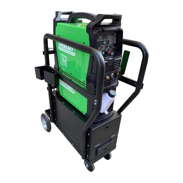
Everlast PowerCool 375 User manual

Operator’s Manual
Publish Date: JUNE 2021
EV-PC350-240V Rev. 1
USA/North America
©Everlast Power Equipment
240V
Welders, Plasma Cutters, Multi-Process
Safety, Setup and General Use Guide
FUNCTION: Water Cooler
PURCHASE DATE:
SERIAL NUMBER:
375A

2
TABLE OF CONTENTS
SPECIAL NOTICE AND CALIFORNIA PROPOSITION 65 WARNING 3
CUSTOMER GREETING AND EXPLANATION OF PROCEDURES 4
WARRANTY AND CONTACT INFORMATION 5
SAFETY DISCLAIMER AND HF WARNING 6
SAFETY WARNINGS, DANGERS, CAUTIONS AND INSTRUCTIONS 7
SPECIFIC VOLTAGE AND WARNING INFORMATION 10
SPECIFICATIONS AND COMPONENTS 11
COOLANT TYPE AND USE 12
SETUP GUIDE/GETTING STARTED 13
COMPONENT ID AND EXPLANATION 14
PARTIALLY DISASSEMBLED SIDE VIEW OF COMPONENTS (EXPLODED VIEW) 15
CONNECTING THE TIG TORCH 16
MAINTENANCE 16
SECURING THE WELDER AND COOLER TOGETHER 17
INSTALLING LOCKING PADS TO CART AND COOLER 18
INSTALLING SECURING BRACKETS TO WELDER AND COOLER 19
INSTALLING WELDER TO COOLER 20
TROUBLE SHOOTING FLOW ALARM ISSUES AND NO RUN ISSUES 21

3
NOTICE:
Product Specications and features are subject to change without notice. While
every attempt has been made to provide the most accurate and current infor-
mation possible at the time of publication, this manual is intended to be a general
guide and not intended to be exhaustive in its content regarding safety, welding,
or the operation/maintenance of this unit. Due to multiple variables that exist in
the welding eld and the changing nature of it and of the Everlast product line,
Everlast Power Equipment INC. does not guarantee the accuracy, completeness,
authority or authenticity of the information contained within this manual or of any
information offered during the course of conversation or business by any Everlast
employee or subsidiary. The owner of this product assumes all liability for its use
and maintenance. Everlast Power Equipment INC. does not warrant this product
or this document for tness for any particular purpose, for performance/accuracy
or for suitability of application. Furthermore, Everlast Power Equipment INC. does
not accept liability for injury or damages, consequential or incidental, resulting
from the use of this product or resulting from the content found in this document
or accept claims by a third party of such liability.
WARNING!
California Proposition 65 Warning:
This product, when used for welding or cutting, produces fumes or gases which
contain chemicals known to the State of California to cause birth defects and, in
some cases, cancer. (California Health & Safety Code § 25249.5 et seq.)
Warning: Cancer and/or Reproductive Harm
www.P65warnings.ca.gov

4
THANK YOU! We appreciate you as a valued customer and hope that you will enjoy years of use from your plasma cutter. We work to please the cus-
tomer by providing a well supported, quality product. To make sure that you receive the best quality ownership experience, please see below for im-
portant information and time sensitive details.
What to do right now:
1. Print your receipt from your conrmation email that should have been sent to you after your purchase and put it up for safe keeping. If you do not
have one, contact us at 1-877-755-9353 (US customers) or 1-905-570-1818 (Canadian Customers). You will need this if anything should ever
happen for original owner verication (if bought as a gift, original receipt will still be needed, or explanation sent to Everlast).
2. Read this manual! A large number of tech and service calls are a result of not reading the manual from start to nish. Do not just scan or casually
peruse this manual. There are different features and functions that you may not be familiar with, or that may operate differently than you expect.
Even if you have expertise in the eld of welding, you should not assume this unit operates like other brands or models you have used.
3. Carefully unpack and inspect all items immediately. Look for missing or damaged items. Please report any issues within 48 hours (72 hours on
weekend or holidays) of receiving your product,. Take pictures if you are able and contact us at 1-877-755-9353, ext. 207 if any issue is discov-
ered between 9 am and 5 pm Eastern Time M-F (US customers) or at 1-905-570-1818 (Canadian Customers) between 9am and 4 pm weekdays
except on Fridays when hours are from 9 am to 12pm Eastern. If outside of the US or Canada, contact your in-country/or regional distributor di-
rect at their service number.
What to do within the next 2-3 days:
1. Make sure your electrical system is up to date and capable of handling the combined inrush and rated current of the unit and the welder. (Add the
Inrush and rated currents together to get the total breaker and wiring requirements.) Consult and use a licensed and knowledgeable electrician. If
you have downloaded this manual in expectation of delivery, get started now.
2. Make sure this machine is plugged in, turned on, and tested with every process and major feature, checking for proper function. You have a 30
day period to test and thoroughly check out the operation of this unit under our 30 day satisfaction period. If something is wrong, this policy co-
vers shipping on the unit (30 day satisfaction policy applies to the USA only for the 48 lower states and D.C., territories and provinces are exclud-
ed) or any incidental parts that may be needed to resolve any issue. After this 30 day period, if you nd something wrong with the unit, you will not
receive the benet of free shipping back and forth to resolve this issue. Your unit is still covered under the 5 year parts/labor warranty, but ship-
ping is covered by the customer after the 30 day period is over. The rst 30 days of operation with any electronic item is the most critical and if
any issue will happen, it will often happen during this time. This is why it is very important that you put this unit to work as soon as possible. Any
issue should be reported within 48 hours (72 if on the weekend or holiday). Everlast will not be liable for any shipping after that time.
What to do within the next 30 days:
Visit our website (US customers). Go to www.everlastwelders.com. Navigate to the resources tab and to the “product registration” page to register
your product. While keeping your receipt/proof of purpose is still required for verication of ownership, registering will help us keep your details
straight and establish a chain of ownership. Don’t worry, though, your warranty is still valid if you can’t do this. Remember: Always keep your receipt
even if you register. You may want to staple a copy to your manual.
What to do if you have a warranty issue or problem with the unit:
1. Unplug the unit. (Also do this before any maintenance or cleaning is done.)
2. Do not attempt a self-repair until authorized by an Everlast representative. This does not include performing routine maintenance such as point gap
adjustments or regular internal cleaning. Any third party repairs are not covered under warranty, and can further damage your unit.
3. Within 24-48hours, (or by the next working business day) you must contact U.S. tech support at 1-877-755-9353 ext 207(U.S. hours are 9 am to
5pm Eastern for tech support and 9 am to 5 pm Pacic for the business/sales ofce). If you are in Canada contact 1-905-570-1818 (Canada hours
are 9am to 4pm M-Th, 9am to 12pm Fri). Although phone contact is preferred to establish a warranty claim, you may send an email to
tech@everlastwelders.com (US) or mike@everlastwelders.ca (Canada) along with your contact information and brief explanation of the issue and
ask for a follow up call. If you contact us via phone, and you do not reach a live person, please leave a brief message with the nature of your prob-
lem and your contact information. You should expect a call back within 24 hours. It is also a good idea to follow up the message with an email.
4. Be prepared with as much information as possible when you talk with a tech advisor, including a details of the failure, settings, and application of
the unit. NOTE: A Proof-Of-Purchase (receipt) is required before returning the unit for warranty or before warranty parts can be sent to you.
5. Keep in mind that, you may be asked to check a few basic things. Before you call, having a screwdriver and volt/ohm meter at hand is a good idea
and will save time. Many issues can be resolved over the phone. If the issue cannot be resolved over the phone/email, you may be given an op-
tion to return the unit, or have a part shipped to you, at Everlast’s discretion. Keep in mind, you may be asked questions that seem basic, or ele-
mentary to your knowledge base. These are not meant to question your knowledge, but rather to make sure nothing is overlooked. However the
tech chooses to proceed, please cooperate with the process, even if you think you know what the cause or issue is. You may be asked to check
something or open the unit during the diagnosis. This does not void the warranty! Opening the unit is a part of routine maintenance and cleaning.

5
This is an important step. The willingness of the customer to work with tech support can save lots of time and accelerate the warranty process.
For warranty to be honored, you will need to make sure that you follow these guidelines. Units that are returned without an RMA (issued by the
tech support department) may not be repaired under the warranty agreement and you may be charged for the repair and can result in a delayed
repair as well.
What to do if you need setup help, guidance, weld issue diagnosis or have general product compatibility questions.
Call us at 877-755-9353 ext. 204 for welding guidance and general welding issue diagnosis. Or email performance@everlastwelders.com with the basic
issue you are having, along with your specic settings, and welding application.
Hey...wait, what is my warranty?
Warranties and service policies and procedures vary from country to country and are maintained and supported by the region-
al or in country distributor of Everlast welding equipment.
USA Customers Only: For full details on the 5 year parts and labor warranty, 30 day satisfaction policy, terms of sale, and how to proceed with a war-
ranty claim, please visit: https://www.everlastgenerators.com/standard-warranty. Accessories are covered by a separate warranty and detailed infor-
mation can also be found at the link above.
Canada Customers Only: For full details on the 3 year parts and labor warranty, terms of sale, and related policies and procedures, please visit: https://
www.everlastwelders.ca/terms.php.
Who do I contact?
USA Technical Support:
Email: tech@everlastwelders.com
1-877-755-9353 ext. 207
9am-5pm Eastern (Closed holidays)
Monday-Friday
USA Welding Support and General Product Information:
Email: performance@everlastwelders.com
1-877-755-9353 ext 204
9am-6:30 pm Eastern (Closed holidays)
Monday-Friday
USA Sales and Main Ofce:
Email: sales@everlastwelders.com
1-877-755-9353 ext 201
9am-5pm Pacic (Closed holidays)
Monday-Friday
Canada Technical Support:
Email: mike@everlastwelders.ca
905-570-1818
9am-4pm Eastern Monday-Thursday
9am-12pm Eastern Friday
Canada Sales and Main Ofce:
Email: sales@everlastwelders.ca
905-570-1818
9am-4pm Eastern Monday-Thursday
9am-12pm Eastern Friday
Other Countries and Regions:
Visit the U.S. Website @ www.everlastwelders.com and click on the flag of the country or region represented that is closest to you. If your country or

6
Safe operation and proper maintenance is your responsibility.
Everlast is dedicated to keeping safety a top priority. While we have compiled this operator’s manual to instruct you in basic safe operation and
maintenance of your Everlast product, it is no substitute for observing safe welding practices and behavior. Safe welding and related cutting
operations require basic knowledge, experience and ultimately the exercise of common sense. Welding does signicant hazards to your health
and life! Exercise extreme caution and care in all activities related to welding or cutting. Your safety, health and even life depends upon it.
WARNING! If you do not have proper knowledge or capability to safely operate this machine, do not use this machine until proper
training has been received!
While accidents are never planned, preventing an accident requires careful planning. Stay alert!
Please carefully read this manual before you operate your Everlast unit.
The warranty does not cover damage or harm created by improper use. neglect of the machine or failure to follow safe operating practices.
NOTICE:
Welding and cutting operations may generate undesirable High Frequency (HF) and EMF
energy. This can interfere with surrounding electronic equipment such as computers,
routers, CNC equipment, televisions, radios, fluorescent lighting etc. If disturbance in
surrounding electrical and electronic equipment is noted, consult a licensed electrician to
help properly ground surrounding equipment to limit the interference. This machine may
cause GCFI and ground fault outlets to malfunction. This unit is designed to be operated
on a dedicated, properly grounded circuit.

7
Safety Warnings, Dangers, Cautions and Instructions
NOTICE. This unit manual is intended for users with basic knowledge and skillset in weld-
ing. It is your responsibility to make certain that the use of this plasma cutter is restricted to
persons who have read, understand and follow the warnings and instructions in this manu-
al. If you or the operator needs further instruction, contact Everlast welding support at 1-
877 755-9353 ext. 204 or seek qualied professional advice and training.
WARNING! High Frequency (HF) energy can interfere with the operation of pacemakers and
can damage pacemakers. Consult with your physician and pacemaker manufacturer before
entering an area where welding and cutting equipment is in operation and before using this
plasma cutter. Some pacemakers have limited shielding. Alert any users or customers of
WARNING! Use approved safety glasses with wrap around shields and sides while welding
and working in the weld area or serious eye damage or loss of vision may result. Use a
grinding shield in addition to the safety glasses during chipping and grinding operations.
WARNING! When welding always use an approved welding helmet or shielding device
equipped with at least an equivalent of a shade 9 or greater. Increase the shade number
rating as amperage increase over 100 amps. Inspect helmet for cracks in lenses and in the
helmet. Keep lens covers in good condition and replace as necessary.
WARNING! Welding/cutting operations carry inherent risks which include but not limited to
possible cuts burns, electrical shocks, lung damage, eye damage and even death. Take all
appropriate measures to use proper Personal Protective Equipment (PPE). Always use
leather welding gloves, closed toe (preferably reinforced or steel toe leather shoes, and long
-sleeved flame resistant clothing (i.e. denim). Do not wear Poly/Nylon blend materials.
DANGER! Welding/cutting poses shock and electrocution risks. Keep this welding equip-
ment dry. Do not weld in the rain or where moisture accumulates. Use dry, rubber soled
shoes, gloves and clothing when welding. Do not rest or contact work clamp (ground) when
welding. Keep all parts of the body insulated from the part being welded when possible. Do
not touch terminals or connections while the unit is on. Consider all parts to be “live” at all
times even if no live work is being performed. Do not use frayed welding cables.
CAUTION! Fires are possible but also preventable while welding. Always remove flammable
rags, papers, and other materials from the weld area. Keep rags stored in an approved flame
proof canister. Keep a fully charged re extinguisher at hand. Remove any fuels, oils,
paint, pressurized spray cans, and chemicals from the weld area. Make sure any smoke/re
detectors are function properly. Do not weld on tanks, drums or barrels, especially if pres-
surized or sealed. Do not weld on any container that previously held fuel or chemicals.
Make sure the weld area is clear of flammable materials such as grass or wood shavings
solvents and fuels. Do not wear frayed or loose clothing. Visually inspect and recheck the
work area after welding looking for smoldering debris or flames.
WARNING! Welding gas cylinders are under high pressure. Keep all gas cylinders upright
and chained to a cart or held safely in a safety holding pen. Never transport gas cylinders
in an enclosed car van or other vehicle. Transport gas cylinders securely. Keep all cylin-
ders capped while not in use or during transport. Replace the cap on the cylinder when it
is going to be more than 24 hours before use. Do not use or attempt to repair faulty regu-
lators. Never weld on gas cylinders. Keep gas cylinders away from direct sparks.

8
Safety Warnings, Dangers, Cautions and Instructions
DANGER! Welding and cutting operations pose serious inhalation hazards. Some of these
hazards are immediate while others are cumulative in their effect. Do not weld in enclosed
spaces or in areas without adequate ventilation. Fumes and gases released in the welding
and cutting operations can be toxic. Use fans or respiration equipment to insure adequate
ventilation if you are welding in a shop or garage area. Do not weld on galvanized metal
under any circumstance. You may develop metal fume fever. Symptoms are similar to lu-
like symptoms. Seek medical advice and treatment if you are exposed to galvanized weld-
ing fumes.
If you experience any eye burning, nose or throat irritation while welding, these are signs
that you need more ventilation.
If you feel these symptoms:
• Stop work immediately and relocate work area with better ventilation.
• Wash and clean your face and hands.
• Stop work completely and seek medical help if irritation persists
DANGER! Never use brake cleaner or any chlorinated solvent to clean or degrease metal
scheduled to be welded or other related equipment in the area being welded. The heating
of this cleaner and its residue will create highly toxic phosgene gas. Small amounts of
this vapor are harmful and can lead to organ failure and death. If degreasing of a part is
necessary, use Acetone or an approved pre-weld cleaner. Use the proper personal protec-
tive equipment (PPE) when handling any cleaners/solvents.
DANGER! People with pacemakers should consult a physician and pacemaker manufactur-
er before welding. There is a potential for damage or serious malfunction resulting in
death. High Frequency energy (HF)/Electromagnetic Fields generated during welding can
interfere with pacemaker signals, even permanently damaging it. Some pacemakers offer
some shielding, but restrictions regarding amperage and HF starting of TIG arcs may be
placed upon the individual. Warn all potential bystanders that they should exit the work
area if they have a pacemaker or similar medical equipment before welding. Severe electri-
cal shock leading to injury or death may occur while using the plasma cutter if the user
becomes part of the circuit path. While the Amp output of the plasma cutter is limited, the
unit may produce an OCV of 300V or greater. Consult with a Physician if a pacemaker is
DANGER! Never defeat or modify any safety guards or shields. Keep all safety covers and
shields in place.
Never place your ngers in or near a fan shroud or insert any object into the fan(s).
DANGER! Do not supply more than 100 PSI to the air-pressure regulator supplied with
this machine. If you do, the regulator may leak or explode, causing severe injury or
death. Use a separate regulator mounted at the air-compressor to control supply air pres-
sure. Never use an air compressor without a separate compressor mounted air regulator!

9
Safety Warnings, Dangers, Cautions and Instructions
CAUTION! Trip Hazards exist around plasma cutters. Cords, cables, welding leads and hos-
es pose a trip hazard. Be aware of their location and inform others of their location. Tape
and secure them so they will stay out of high trafc areas.
CAUTION! Welded metal can stay hot long after welding is completed. Burns may occur.
Always wear gloves or use tongs/pliers when handling welded or cut metal. Remember
the heat from the metal may catch other material on re. Always have a re-proof area
ready to place welded components until they fully cool. Use soap stone or a metal marking
marker to label the metal as “HOT” to serve as a reminder to all present in the area.
CAUTION! Welding and cutting operations generate high levels of ultraviolet (UV) radiation
which can burn and damage skin and eyes. The intensity is so high that exposed skin and
eyes can burn in a few minutes of exposure. Minimize direct skin and eye exposure to this
intense form of radiation by using proper PPE and sun screen where appropriate.
CAUTION! Do not allow bystanders. Do not allow others without proper Personal Protec-
tion Equipment (PPE) suitable for welding to stand in the welding area or to observe weld-
ing and welding related activities. If protection is not readily available, use a welding
screen to separate the welding area from the rest of the area. If no protection or screen is
available, physically exclude them from the welding area by a wall or other solid divider.
Keep all pets and young children away from the welding area.
CAUTION! Electromagnetic Fields can be generated by this plasma cutter and radiate into
the work place. The effect of EMF is not fully known. Exercise caution when welding by:
NOT draping welding leads (guns/cables) over your shoulders or arms, NOT coiling them
around your body, NOT inserting yourself directly between the cables, and by NOT con-
tacting the unit while welding. DO keep the work clamp connected as close as possible to
the area of the weld and directly to the object being welded whenever possible.
DANGER! Never touch connectors or ttings while this machine is turned on. Keep all
safety covers in place when not in use. Never remove or replace the plasma consumables
while the machine is turned On. Make sure the brass switch safety pins on the torch head
remain in good repair and that the spring loaded function remains operational and keeps
them fully extended when the torch cap is removed. The Open Circuit Voltage (OCV) while
in plasma mode may exceed 400V. This is enough to cause burns, injury severe electrical
shock, injury and instant death.
DANGER! Use of this product may result in a hazardous fluid waste. Drinking or ingesting
the coolant may cause serious injury or death. Keep children and animals away from any
overll, leak or empty containers. Recycle coolant in appropriate areas that accept recycled
fluids. Do not pour coolant down drowns, or dispose of in streams, lakes or water shed
areas. If storage of spent product is necessary, use an appropriate container, and mark the
label clearly as to contents. When possible use environmentally safe products, or products
that include safe recycle or disposal instructions.

10
Using This Unit with Everlast Welding Products.
This water cooling unit is designed for 240V use only. It’s unique stackable (and nearly seamless) design means that it can be used in
conjunction all new generation PowerTIG and PowerPro units. (Except PowerTIG 185DV). All PowerTIG and PowerPro models, except
the PowerTIG 185DV are equipped with a special water-cooler power plug located on the rear of the unit. Even though the PowerPro
164, PowerTIG 200DV, PowerTIG 210EXT, and PowerTIG 255EXT offer dual voltage(120/240V) operation, the PowerCool 350 should not
be used with the these welders while they are operating on 120V input. The Power Plug on the rear of these units is connected directly
to the switch and does not run through a step-up transformers to alter the power. This means that the plug supplies 120V while operat-
ing on 120V, and 240V while operating on 240V input power.
Why isn’t this water-cooler dual voltage for dual voltage welders, so I can operate the cooler on 120V?
The 120V input power operating capability of the Everlast PowerTIG and PowerPro welding products is primarily intended for portable
welding applications where 240V is not available at all. This means that the unit is usually being transported and used without the water
cooler, especially since 120V output of the welders is limited to either, depending upon the model, 125A or 150A. Additionally, the
weight, space limitations and added inconveniences in general, most people nd that carrying a cooler in portable applications is prohibi-
tive. In any case, the Amp range provided, while operating on 120V input power, is the Amp range that can be easily covered by the use
of most air-cooled (gas-cooled) torches. All dual voltage units include at least one gas-cooled torch that should be sufcient for use with
either all or most of the range of the welder while operating on 120V.
WARNING! Never use a water-cooled torch without a water-cooler or with the water-cooler turned off or disconnected (even for a few
seconds) or damage may result to the torch, including melting of the torch cables internally, re due to burn through, or other damage.
Damage will occur to the torch even while welding at low Amperages.
WARNING!
Never use the electrical power outlet on the back of your Everlast welding machine for anything other than powering an Everlast brand
water cooler. Do not attempt to modify, or otherwise change this outlet for use with anything else other than an Everlast brand water cool-
er designed for 240V operation. Severe damage, re or injury may occur if other devices or other brand equipment is connected.
NOTICE!
This unit is designed to cool water via conventional heat-air exchange. This is not a water chiller. The water may be warm or even
slightly hot in the coolant tank, torch and water lines during circulation. Do not expect this unit to drop the water temperature to a cooler
temperature than ambient air temperature. In most cases, during heavy use, the water temperature will be well above ambient air tem-
perature. This should not be a concern as long as the cooling capacity is observed and the unit is maintained with proper coolants at
proper levels. Should the Alarm sound however, stop immediately and check for coolant flow to prevent overheating.

11
Specifications and Components
Specifications PowerCool 375
Item Description Stackable-Design TIG/MIG Torch Water-Cooler
Heat Exchanger (Radiator) Construction type Copper Core type
Cooling System Design Direct drive sealed industrial motor connected to fan and pump on a single shaft
Amp Rating 1.1A
Voltage 240V (±10%) 50/60Hz
Operating Pressure 45 to 57 psi
System Fluid Capacity Approximately 2 gallons/ 7.5 Liters
Flow Rate (at connector)/Cooling Capacity .26 GPM (1 qt/minute)/ 1LPM (16.6kW)
Pump Stainless with Bronze Impellor
Rated Cooling Amperage 375A @ 100% Duty Cycle
Minumum-Maximum Operation Temperature 14-104 F/-10-40 C
Dimensions 27.5” L X 10” W x12” H
Bare Unit Weight 25 Lbs.
Water Connection 9mm quick connect
Ingress Protection IP21
Coolant Type
Use only name-brand commercially produced TIG coolant rated for low conductivity or for
HF TIG use. Do not use or substitute any other type. Distilled water may be used temporarily
for no more than 3 months.
Minimum Storage/ Minimum Operating Temperature 0 F/14 F

12
Specifications and Components
What Coolant Fluid Should I Use?
Quality TIG water cooler coolants are available from most any welding supplier. Everlast recommends only a quality, name-brand, commercially-
manufactured TIG water cooler coolant for your PowerCool product from major manufacturers. Coolant selection is important to both the life span of
the cooler and the torch itself. Furthermore, it is necessary to keep your warranty on your cooler and torches valid. Most coolants are pre-mixed. Be
sure to consult the coolant manufacturer’s recommendation. If dilution is required, dilute with distilled or deionized water, or per the coolant manufac-
turer’s instructions.
Look for the following when selecting your TIG water cooler coolant:
• Make sure the coolant is rated for TIG High Frequency (HF) use. Some coolants are for MIG, Plasma Cutting and DC scratch start/lift TIG. These
coolants are considered “conductive” and can drain HF energy from the torch, making arc starting difcult or erratic. A coolant rated for HF use is
considered to have “low conductivity”.
• Quality TIG water cooler coolants include line conditioners and lubricants. These help extend the pump life and helps to prevent degradation of
the TIG torch and cooler components.
• Quality TIG water water cooler coolants have anti-algae additives included to prevent clogging of tiny torch orices and lines.
• Quality TIG water Ethylene Glycol based cooler coolants have anti-freeze properties which protect from freezing down to at least –32 F.
Distilled water may be used, for not more than 3 month period, until the proper coolant is purchased. However, this is considered to be a temporary
concession until the proper coolant is located and purchased. Under no circumstances should distilled water only be used.
Use of non standard, non name-brand coolants will jeopardize warranty status on both torches and the cooler itself.
Please do not use “home brew” or low quality (cheap) TIG coolants. Even if they are commercially sold, or recommended are often repackaged coolants
or antifreezes that are crossed over from other industries as a “will work” coolant.
NOTICE: Water cooler coolant recommendations have varied by the manufacturer and model of cooler over the years as materials have changed and a
wider variety of coolants have become available. However, as more specialized coolants, and new materials have become available, these older types
of coolants once used have fallen out of favor as they may now can cause damage to the cooler or torch components. The types of damage seen by the
use of such coolants is often associated with rapid aging of torch cables and components (dry rotting), torch head plugging, bearing seizure in the
pump, leaks, and other similar issues. The use of such older types and of inferior or “home brew” concoctions will void the warranty of both the torch
and cooler.
Which Coolant Fluid(s) Should I Stay Away From?
Stay away from any of the following coolants. Use of these coolants will void your warranty:
• Any Automotive type, regardless of color or similarity to commercial TIG low conductivity coolants.
• Propylene Glycol
• Alcohol, including Isopropyl.
• RV type and other similar Pink or Blue non TIG labelled coolants.
• Low quality or cheap repackaged coolants sold by some companies that are designed for use in other industries.
• TIG coolant not specied as low conductivity by the manufacturer.
• Any TIG coolant that you suspect may be of low quality, or repackaged coolant, not originally intended or labelled specically for low conductivity
HF TIG use.
• Well water, or municipal supplied water, or any water not labelled as distilled or deionized.
• Deionized or Distilled water for time periods over 3 months, unless required to dilute a concentrated coolant.

13
Setup Guide
Getting Started
UNPACK YOUR UNIT.
Upon arrival, you will need to completely unpack your unit, and check
things over. This is a time sensitive matter. Do not delay or hold the
cooler unopened in the box. First, make sure the unit is opened from
the top. Be careful with using knives and sharp objects so you won’t
cut cords and cables inside the boxes. Lay all items out and inspect
them.
You should have the following in your box:
1. Water Cooler.
2. Four (4) Plastic Cooler Foot Pads.
3. Two (2) welder to Cooler Connection Brackets
4. Six (6) M4 Screws
5. Four (4) M5 Screws
6. Cooler line extensions (some regions)
When you receive your package, inspect the cooler for damage. Check
for the presence and general condition of the unit Some slight rubbing
or chafng of some of the accessories may be present, but this is con-
sidered normal. There may be some moisture present in the box, par-
ticularly if the unit has been turned upside down during shipping. This
is normal as the unit has been factory tested before shipping. A small
amount of water may remain in the pump or coolant tank and leak out.
If any item is damaged or missing, please inform Everlast within 72
hours of product receipt. See pages 4 and 5 for more details.
POWER UP AND TEST YOUR UNIT.
You will need to fully test the unit as soon as possible. Within 72 hours
after receipt of the unit, be sure to have every thing you need at hand
to test the unit such as the proper coolant. Then, power up your ma-
chine with the torch installed. Allow the unit to idle for 5 minutes.
Check and observe operation of the cooler. Make sure the fan is run-
ning at full speed. Check for leaks. After the test is completed, turn
the unit off, See page 5 for more information. If the cooler was deliv-
ered before your welder, please make note of that, and let Everlast
know you may have a delay in testing the unit properly until it arrives.
NOTICE: Cosmetic damage claims after 30 days will not be accepted,
unless Everlast is contacted and informed of such delay and reason for
such a required delay (i.e. Overseas in deployment).
CHECK FOR AIR LEAKS.
Be sure to check for gas leaks before attempting to weld Connect all
the lines and tighten and recheck any related clamps, plugs and t-
tings.
DISTANCE YOUR WELDER/COOLER FROM YOUR WORK.
As a best practice technique, be sure to locate your welder/cooler com-
bination away from the immediate area you are welding. Sparks and
debris thrown by the welding and cutting processes can enter the unit
and cause damage. Do not intentionally cut or grind near the units.
Keep in mind the fan draws air in from the rear and exhausts out the
front and the sides of the unit.
GIVE YOUR WELDER/COOLER SPACE TO COOL.
The welder/cooler units need room to cool itself. Place the unit in a
place that will allow 18” from all sides to allow for proper cooling. The
units pulls air in from the rear, and pushes it through the units heat
sinks and radiator. The air is then exhausted through the front panel
and side louvers of the unit. If any of sides is blocked or restricted,
the duty cycle will be reduced, and overheating will occur, leading to
possible damage if the restriction is severe enough. Never attempt to
restrict air flow by attaching lters to the vents or by modifying your
fans for “on demand” service.
PRIMING THE PUMP/REMOVING THE AIR LOCK
When you receive your unit, and you connect it to the TIG torch for
the rst time, you will need to make sure the pump has been
properly primed and water is flowing through the torch before you
begin welding. This unit is equipped with a flow alarm. Usually this
will sound if flow is not sufcient or blocked. This may also be
required if the cooler has been emptied or has sat for long periods
of time without use.
To do this:
• Fill the cooler with coolant.
• Connect the torch per color code.
• Plug the unit into the welder and switch the welder on.
• Disconnect the return from the torch and discharge it directly
into the opening of the coolant tank. (Alarm should sound)
• Watch to see if coolant is being discharged directly into the
tank.
• If water is flowing, and a steady stream, reinstall the line.
(Flow is approximately 1qt/minute)
• If water is not flowing, allow the pump to continue to pump for
a couple of minutes to see if it will prime by itself.
• If water does not begin to flow, you will need an air compres-
sor regulated down to 25 psi at the output side of the com-
pressor, an air gun, and a shop rag.
• Connect the air gun and wrap the shop rag around the air gun
nozzle.
• Remove the torch hose from the opening of the coolant tank,
and stick it in a small jar or can.
• Insert the air gun into the tank, so that the rag offers a light
seal. This should not be 100% air tight, but enough to build
slight pressure in the coolant tank.
• Give several quick, but successive shots of air into the coolant
tank while the cooler is running.
• This should clear the air lock and force water into the pump.
• Repeat until it water is flowing.
• CAUTION! Do not use extremely high air pressure, or use long
pressurizations, or attempt to make a completely air tight seal
around the opening of the coolant tank. The rag should form a
light seal, so that some air can escape if over pressurized.

14
Specifications and Components
!
1
2
3
5
6
7
9
4
10
10
8
11
#DescriptionItem
1The cooler power switch may be left in the on position if it is connected to an Everlast welding product if the unit is to be used on and off during a production
cycle. This will allow the main power switch on the welder to control the power. If storing, or if not in use overnight, switch the cooler off with the power switch.
Power Switch
2The warning alarm is designed to sound if coolant flow is interrupted. This will protect the torch hoses from being damaged in the event of coolant flow interrup-
tion. Common causes that will trigger this alarm are: Low Coolant Level, Disconnected or Improperly connected torch cables, plugged torch head (from defect or
algae), too thick of coolant, leak, or damaged quick connector.
Warning Alarm
(Coolant Alarm)
3If the coolant reaches this water level mark, immediately stop and rell the cooler tank to the full level with approved coolant.Low Coolant Level
4Periodically drain and replace coolant. This will help prevent algae growth and breakdown of the coolant while maximizing torch life.Drain
5 This tank holds approximately 7 liters. This is approximately 2 gallons. Coolant Tank
6This quick connect tting provides cooled water under pressure to the torch. It should be connected to the blue torch line if color coded.Coolant Out (Blue)
7This quick connect tting provides return water from the torch that has been heated and now needs to be cooled. It should be connected to the red torch line if
color coded.
Coolant In (Red)
8Connector Seat This area positively engages the welder when the welder is stacked onto the top of the cooler. The upper unit should sit flat.
9Carry Handle The cooler can be independently carried to where it is needed. This handle is removeable if vibration occurs while both units are running.
10 Rear Connection These holes are connected to the welder via the brackets provided with the cooler. See following pages for more information.
11 IEC 60320-1 C-13
Power Plug
This plug is designed to work correctly with all Everlast products with rear water cooler power connections in the rear. Do not convert or change this plug.

15
Specifications and Components
End Panel
Mating Block Top Handle
Top Panel
Side Panel
Power Cable
Radiator/Heat Exchanger
Sealed Industrial Motor
Pump
Coolant Tank
Coolant IN
Coolant OUT
Power Switch
Flow Alarm
Flow Alarm Sensor Relay
Side View of Disassembled Components

16
CONNECTING TORCH LINES AND WHAT TO DO IF THE LINES ARE NOT COLOR CODED.
Most water cooled torches feature color coding which makes it easy to connect the torch to the welder. The blue torch line connects to
the blue color coupling, and the red torch line connects to the red coupling. The remaining line (usually black in color) connects to the
gas connection.
In some instances, some companies do not color code their torch lines, but may be labeled as to where each goes. Be sure to look
closely for instructions on where to connect the lines. They’ll usually have a paper tag on the torch lines near the tting. If using a torch
other than Everlast, the connections themselves for the water lines will have left handed threads and will tighten in the opposite direction-
of conventional ttings. These ttings will require adapters to connect to the quick couplings. These are available usually from the torch
supplier, or some universal type are available from Everlast to convert your torch, but your original ttings will have to be removed rst.
In some cases, the torch manufacturers rely on customer knowledge and tradition to connect the lines properly. If you do not have a
torch with color coded gas and water lines, then use the following information as a guide to properly connecting your torch:
• The line from the DINSE connector is the hot water return line. This should be connected directly to the red coupling (IN). This line
is usually larger than the others. At the very least the line to the DINSE connector from the torch is larger than the other lines.
• Gently blow low pressure air through the other lines to determine which is the gas line.
• If you are blowing air through a line and the air escapes from the torch head, you have identied the gas line. Connect it to the gas
coupling on the welder.
• If you are blowing air through a line and the air escapes from the line coming from the DINSE connector, this is the cool water line
that supplies cooled water to the torch. Connect this to the blue coupling (OUT).
Setup Guide
MAINTENANCE
Every 3 to 6 months, the cover of the water cooler should be removed to access it for cleaning and to inspect it for leaks. Pay special
attention to the cooling ns on the radiator. Shine a light behind the ns while looking on the other side to see if the radiator ns are
plugged or dirty. Clean with light compressed air. Do not use coil cleaner on the ns to clean the radiator. If they are completely
plugged, then the radiator will need to be removed and the ns rinsed with water and a mild detergent.
The cooler tank should be drained regularly (at least yearly), depending upon the type of coolant used, and inspected for algae growth,
and debris buildup in the bottom of the tank. If algae has been discovered, rinse tank with water completely. Then, ll with a 5% mix of
bleach to water and allow to sit for 20 minutes. Remove water/bleach mixture, and thoroughly rinse again. Additionally, check torches
for plugs by blowing through the lines with air pressure set to no more than 25 psi. Cycle fresh, distilled water through torch. Connect
both the torch and cooler together and ll with distilled water. Allow the cooler to run for 10 minutes. Drain the tank again. Replace
coolant with fresh coolant. Recycle or properly discard the used coolant. Do not reuse coolant that has had algae, sludge or debris in it.
CHECK FOR LEAKS
When you receive your unit, the units have been factory tested for leaks. However, due to shipping damage, and possible loosening or
hidden damage, some leaks may be possible after initial startup.
After the pump has been primed, and the torch has been properly connected, switch the cooler on, and allow it to run for at least 15
minutes, checking for any drips, leaks or abnormal wetness around the cooler and torch ttings.

17
Setup Guide
SECURING THE COOLER AND THE WELDER TOGETHER
This cooler is designed specically for the new generation panel design. It is designed to make a seamless match to the up-
per welder unit, completing the stylish new look of the welder/cooler package. The cooler and welder can be attached togeth-
er semi-permanently through the exclusive new mating system. This will allow the units to be more stable while moving and
transporting and make theft (due to the combined size/weight) more difcult of either unit. Use this over-view image and the
detailed images and instructions on the next few pages to properly assemble the unit.

18
Setup Guide
INSTALL LOCKING PADS TO CART AND COOLER
In order to offer complete package, Everlast has designed the new PowerCart 330 to mate securely to the welder and cooler
package. The locking pads are designed to hold the cart and cooler together. In turn the mounting system between the weld-
er and cooler also offer a “locked together” function so that all the components can be secured together. This helps to reduce
chance of theft, and also makes the whole package more stable while transporting.
Slide all four of the cooler locking pads up into the edge of the plastic housing on the cooler as shown below. Then use the
m5 screws to secure the cooler to the cart.

19
Setup Guide
INSTALL SECURING BRACKETS TO THE WELDER
The cooler includes two small connector brackets that help secure the cooler to the welder for semi-permanent mounting.
Locate the brackets and install the bracket to the bottom of the welder welder rst using three m4 screws. For ease of installa-
tion, lay the welder on its side to access the bottom plate of the welder.
Once the machine has been mated to the unit (see next page), make sure the remaining screw hole in the bracket aligns with
the hole in the water cooler and install the remaining m4 screws. If necessary, align the holes with a small drift or screw driv-
er.

20
Setup Guide
INSTALL THE WELDER TO THE COOLER
Install the welder to the cooler after installing the securing brackets to the welder (See previous page). Line up the welder
and cooler so that the mating surfaces roughly match, making sure the bottom lip of the welder is slightly in front of the cool-
er lip before they touch. Once the welder is on top of the cooler, and engaging the mounting blocks on top of the cooler,
slide the cooler to the rear until they surfaces are flush along all planes.
Be sure to install the two securing screws at the rear of the unit (see previous page) to hold the welder and cooler in place.
Table of contents
Other Everlast Welding Accessories manuals