Everlast PowerCart 330 Quick setup guide

Assembly and Use Information
Publish Date: Feb. 2020
EVPC3302021 Rev. 1
USA/North America
©Everlast Power Equipment
Welders, Plasma Cutters, Multi-Process
APPLICATION: Welder Cart
PURCHASE DATE:
ACCESSORY SERIAL NUMBER:

2
TABLE OF CONTENTS
SPECIAL NOTICE AND CALIFORNIA PROPOSITION 65 WARNING 3
CUSTOMER GREETING AND EXPLANATION OF PROCEDURES 4
WARRANTY AND CONTACT INFORMATION 5
SAFETY WARNINGS, DANGERS, CAUTIONS CONCERNING GENERAL WELDING 6
GETTING STARTED, UNPACKING CART FOR INSPECTION, ITEMS REQUIRED FOR ASSEMBLY 10
GENERAL CART SPECIFICATIONS 11
COMPONENT IDENTIFICATION AND BREAKDOWN 12
FASTENER KIT CONTENTS 13
UNDERCARRIAGE AND TRUCK ASSEMBLY 14
STANCHION (HANDLE) AND ACCESSORY FINAL ACCESSORY ASSEMBLY 17

3
NOTICE:
Product Specications and features are subject to change without notice. While
every attempt has been made to provide the most accurate and current infor-
mation possible at the time of publication, this manual is intended to be a general
guide and not intended to be exhaustive in its content regarding safety, welding,
or the operation/maintenance of this unit. Due to multiple variables that exist in
the welding eld and the changing nature of it and of the Everlast product line,
Everlast Power Equipment INC. does not guarantee the accuracy, completeness,
authority or authenticity of the information contained within this manual or of any
information offered during the course of conversation or business by any Everlast
employee or subsidiary. The owner of this product assumes all liability for its use
and maintenance. Everlast Power Equipment INC. does not warrant this product
or this document for tness for any particular purpose, for performance/accuracy
or for suitability of application. Furthermore, Everlast Power Equipment INC. does
not accept liability for injury or damages, consequential or incidental, resulting
from the use of this product or resulting from the content found in this document
or accept claims by a third party of such liability.
WARNING!
California Proposition 65 Warning:
This product, when used for welding or cutting, produces fumes or gases which
contain chemicals known to the State of California to cause birth defects and, in
some cases, cancer. (California Health & Safety Code § 25249.5 et seq.)
Warning: Cancer and/or Reproductive Harm
www.P65warnings.ca.gov

4
THANK YOU! We appreciate you as a valued customer and hope that you will enjoy years of use from your welder. We work to please the customer by
providing a well supported, quality product. To make sure that you receive the best quality ownership experience, please see below for important infor-
mation and time sensitive details.
What to do right now:
1. Print your receipt from your conrmation email that should have been sent to you after your purchase and put it up for safe keeping. If you do not
have one, contact us at 1-877-755-9353 (US customers) or 1-905-570-1818 (Canadian Customers). You will need this if anything should ever
happen for original owner verication (if bought as a gift, original receipt will still be needed, or explanation sent to Everlast).
2. Read this manual! A large number of tech and service calls are a result of not reading the manual from start to nish. Do not just scan or casually
peruse this manual. There are different features and functions that you may not be familiar with, or that may operate differently than you expect.
Even if you have expertise in the eld of welding, you should not assume this unit operates like other brands or models you have used.
3. Carefully unpack and inspect all items immediately. Look for missing or damaged items. Please report any issues within 48 hours (72 hours on
weekend or holidays) of receiving your product,. Take pictures if you are able and contact us at 1-877-755-9353, ext. 207 if any issue is discov-
ered between 9 am and 5 pm Eastern Time M-F (US customers) or at 1-905-570-1818 (Canadian Customers) between 9am and 4 pm weekdays
except on Fridays when hours are from 9 am to 12pm Eastern. If outside of the US or Canada, contact your in-country/or regional distributor di-
rect at their service number.
What to do if you have are missing parts.
1. Within 24-48hours, (or by the next working business day) you must contact U.S. tech support at 1-877-755-9353 ext 206 (U.S. hours are9 am to
5 pm Pacic ). If you are in Canada contact 1-905-570-1818 (Canada hours are 9am to 4pm M-Th, 9am to 12pm Fri). Although phone contact is
preferred to establish a missing parts claim, you may send an email to wh@everlastwelders.com (US) or mike@everlastwelders.ca (Canada) along
with your contact information and brief explanation of the issue and ask for a follow up call. If you contact us via phone, and you do not reach a live
person, please leave a brief message with the nature of your problem and your contact information. You should expect a call back within 24 hours.
It is also a good idea to follow up the message with an email.
2. Be prepared with as much information as possible when you talk with us. NOTE: A Proof-Of-Purchase (receipt) is required before missing parts
can be sent to you.
3. What to do if you need setup help, or have general product assembly questions or issues.
Call us at 877-755-9353 ext. 204. Or email performance@everlastwelders.com with the basic issue you are having.
Hey...wait, what is my warranty?
Warranties and service policies and procedures vary from country to country and are maintained and supported by the regional
or in country distributor of Everlast welding equipment.
USA/Canada Customers Only: Warranty is for defects in workmanship only.
Who do I contact?
USA Technical Support:
Email: tech@everlastwelders.com
1-877-755-9353 ext. 207
9am-5pm Eastern (Closed holidays)
Monday-Friday
USA Welding Support and General Product Information:
Email: performance@everlastwelders.com
1-877-755-9353 ext 204
9am-6:30 pm Eastern (Closed holidays)
Monday-Friday
USA Sales and Main Ofce:
Email: [email protected]
1-877-755-9353 ext 201

5
9am-5pm Pacic (Closed holidays)
Monday-Friday
Canada Technical Support:
Email: mike@everlastwelders.ca
905-570-1818
9am-4pm Eastern Monday-Thursday
9am-12pm Eastern Friday
Canada Sales and Main Ofce:
Email: sales@everlastwelders.ca
905-570-1818
9am-4pm Eastern Monday-Thursday
9am-12pm Eastern Friday
Other Countries and Regions:
Visit the U.S. Website @ www.everlastwelders.com and click on the flag of the country or region represented that is closest to you. If your country or
region is not found, call the U.S. ofce at 1-650-588-8588 between the hours of 9am to 5pm Pacic, Monday through Friday.

6
Safety Warnings, Dangers, Cautions and Instructions
NOTICE. This unit manual is intended for users with basic knowledge and skillset in weld-
ing. It is your responsibility to make certain that the use of this welder is restricted to per-
sons who have read, understand and follow the warnings and instructions in this manual. If
you or the operator needs further instruction, contact Everlast welding support at 1-877
755-9353 ext. 204 or seek qualied professional advice and training.
WARNING! High Frequency (HF) energy can interfere with the operation of pacemakers
and can damage pacemakers. Consult with your physician and pacemaker manufacturer
before entering an area where welding and cutting equipment is in operation and before
using welding equipment. Some pacemakers have limited shielding. Alert any users or
customers of this potential problem.
WARNING! Use approved safety glasses with wrap around shields and sides while welding
and working in the weld area or serious eye damage or loss of vision may result. Use a
grinding shield in addition to the safety glasses during chipping and grinding operations.
WARNING! When welding always use an approved welding helmet or shielding device
equipped with at least an equivalent of a shade 9 or greater. Increase the shade number
rating as amperage increase over 100 amps. Inspect helmet for cracks in lenses and in the
helmet. Keep lens covers in good condition and replace as necessary.
WARNING! Welding/cutting operations carry inherent risks which include but not limited to
possible cuts burns, electrical shocks, lung damage, eye damage and even death. Take all
appropriate measures to use proper Personal Protective Equipment (PPE). Always use
leather welding gloves, closed toe (preferably reinforced or steel toe leather shoes, and
long-sleeved flame resistant clothing (i.e. denim). Do not wear Poly/Nylon blend materials.
DANGER! Welding poses shock and electrocution risks. Keep this welding equipment dry.
Do not weld in the rain or where moisture accumulates. Use dry, rubber soled shoes,
gloves and clothing when welding. Do not rest or contact work clamp (ground) when weld-
ing. Keep all parts of the body insulated from the part being welded when possible. Do
not touch both terminals or connections at the same time. Consider all welder parts to be
“live” at all times even if no welding is being performed. Do not use frayed welding cables.
CAUTION! Fires are possible but also preventable while welding. Always remove flamma-
ble rags, papers, and other materials from the weld area. Keep rags stored in an approved
flame proof canister. Keep a fully charged re extinguisher at hand. Remove any fuels,
oils, paint, pressurized spray cans, and chemicals from the weld area. Make sure any
smoke/re detectors are function properly. Do not weld on tanks, drums or barrels, espe-
cially if pressurized or sealed. Do not weld on any container that previously held fuel or
chemicals. Make sure the weld area is clear of flammable materials such as grass or wood
shavings solvents and fuels. Do not wear frayed or loose clothing. Visually inspect and
recheck the work area after welding looking for smoldering debris or flames.
WARNING! Welding gas cylinders are under high pressure. Keep all gas cylinders upright
and chained to a cart or held safely in a safety holding pen. Never transport gas cylinders
in an enclosed car van or other vehicle. Transport gas cylinders securely. Keep all cylin-
ders capped while not in use or during transport. Replace the cap on the cylinder when it
is going to be more than 24 hours before use. Do not use or attempt to repair faulty regu-
lators. Never weld on gas cylinders. Keep gas cylinders away from direct sparks.

7
Safety Warnings, Dangers, Cautions and Instructions
DANGER! Welding and cutting operations pose serious inhalation hazards. Some of these
hazards are immediate while others are cumulative in their effect. Do not weld in enclosed
spaces or in areas without adequate ventilation. Fumes and gases released in the welding
and cutting operations can be toxic. Use fans or respiration equipment to insure adequate
ventilation if you are welding in a shop or garage area. Do not weld on galvanized metal
under any circumstance. You may develop metal fume fever. Symptoms are similar to lu-
like symptoms. Seek medical advice and treatment if you are exposed to galvanized weld-
ing fumes.
If you experience any eye burning, nose or throat irritation while welding, these are signs
that you need more ventilation.
If you feel these symptoms:
• Stop work immediately and relocate work area with better ventilation.
• Wash and clean your face and hands.
• Stop work completely and seek medical help if irritation persists
DANGER! Never use brake cleaner or any chlorinated solvent to clean or degrease metal
scheduled to be welded or other related equipment in the area being welded. The heating
of this cleaner and its residue will create highly toxic phosgene gas. Small amounts of
this vapor are harmful and can lead to organ failure and death. If degreasing of a part is
necessary, use Acetone or an approved pre-weld cleaner. Use the proper personal protec-
tive equipment (PPE) when handling any cleaners/solvents.
DANGER! People with pacemakers should consult a physician and pacemaker manufactur-
er before welding. There is a potential for damage or serious malfunction resulting in
death. High Frequency energy (HF)/Electromagnetic Fields generated during welding can
interfere with pacemaker signals, even permanently damaging it. Some pacemakers offer
some shielding, but restrictions regarding amperage and HF starting of TIG arcs may be
placed upon the individual. Warn all potential bystanders that they should exit the work
area if they have a pacemaker or similar medical equipment before welding. Consult with a
Physician if a pacemaker is expected to be implanted.
DANGER! Never defeat or modify any safety guards or shields. Keep all safety covers and
shields in place.
Never place your ngers in or near a fan shroud or insert any object into the fan(s).

8
Safety Warnings, Dangers, Cautions and Instructions
CAUTION! Trip Hazards exist around welders. Cords, cables, welding leads and hoses pose
a trip hazard. Be aware of their location and inform others of their location. Tape and se-
cure them so they will stay out of high trafc areas.
CAUTION! Welded metal can stay hot long after welding is completed. Burns may occur.
Always wear gloves or use tongs/pliers when handling welded or cut metal. Remember
the heat from the metal may catch other material on re. Always have a re-proof area
ready to place welded components until they fully cool. Use soap stone or a metal marking
marker to label the metal as “HOT” to serve as a reminder to all present in the area.
CAUTION! Welding and cutting operations generate high levels of ultraviolet (UV) radiation
which can burn and damage skin and eyes. The intensity is so high that exposed skin and
eyes can burn in a few minutes of exposure. Minimize direct skin and eye exposure to this
intense form of radiation by using proper PPE and sun screen where appropriate.
CAUTION! Do not allow bystanders. Do not allow others without proper Personal Protec-
tion Equipment (PPE) suitable for welding to stand in the welding area or to observe weld-
ing and welding related activities. If protection is not readily available, use a welding
screen to separate the welding area from the rest of the area. If no protection or screen is
available, physically exclude them from the welding area by a wall or other solid divider.
Keep all pets and young children away from the welding area.
CAUTION! Electromagnetic Fields can be generated by this welder and radiate into the work
place. The effect of EMF is not fully known. Exercise caution when welding by: NOT drap-
ing welding leads (guns/cables) over your shoulders or arms, NOT coiling them around
your body, NOT inserting yourself directly between the cables, and by NOT contacting the
unit while welding. DO keep the work clamp connected as close as possible to the area of
the weld and directly to the object being welded whenever possible.

9
Safe operation and proper maintenance is your responsibility.
Everlast is dedicated to keeping safety a top priority. While we have compiled this operator’s manual to instruct you in basic safe operation and
maintenance of your Everlast product, it is no substitute for observing safe welding practices and behavior. Safe welding and related cutting
operations require basic knowledge, experience and ultimately the exercise of common sense. Welding does signicant hazards to your health
and life! Exercise extreme caution and care in all activities related to welding or cutting. Your safety, health and even life depends upon it.
WARNING! If you do not have proper knowledge or capability to safely operate this machine, do not use this machine until proper
training has been received!
While accidents are never planned, preventing an accident requires careful planning. Stay alert!
Please carefully read this manual before you operate your Everlast unit.
The warranty does not cover damage or harm created by improper use. neglect of the machine or failure to follow safe operating practices.
DANGER!
Improper use and operation of this welding cart may result in cart overturn and can result in serious injury and death.. This may result in loss cylinder
explosion if cylinder is uncapped. Never use this unit on unlevel, unstable ground or while overloaded. Do not modify the cart as change in center of
gravity may occur. Always keep cylinders double chained tightly to the cart. Repair or replace any damaged parts immediately.
IMPORTANT!
After initial assembly and a short period of use, check and retighten all fasteners. Check and retighten all fasteners regularly. Regrease/lubricate
wheels once a year or as needed with heavy gear oil, or axle grease.

10
Setup Guide
Getting Started
UNPACK YOUR CART.
Upon arrival, you will need to completely unpack your cart, and check
things over. Lay the parts out in an orderly fashion on an old towel,
or sheet on a floor or large flat surface. Make sure all parts are there.
The sheet/towel will help protect the unit from scratching during
assembly. You may need to arrange to have a helper to assist in
assembly as some of the parts are large and cumbersome. However,
it is not absolutely necessary if you have a wall or other xed vertical
surface to assist in assembly.
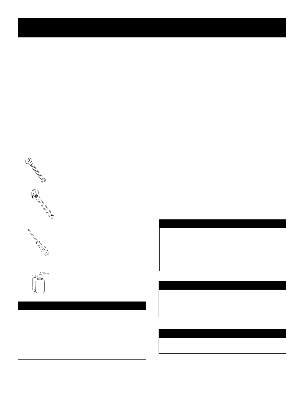
WHAT YOU WILL NEED TO PROVIDE.
You will need a limited amount of items to assemble this unit.
Make sure you have the following to assemble your cart:
TIME REQUIRED:
If you do not have a helper, expect to devote up to 1.5 to 2 Hours for
assembly and 15 minutes to read and review the manual. If you have
a helper, expect to budget 1-1.25 hours for assembly.
MISSING/DAMAGED PARTS?
Contact Everlast at 1-877-755-9353 ext 206 in the USA to order
missing or replacement parts for damaged items. If you are not in the
USA, contact your regional or national distributor for replacement
parts. During the shipping or assembly process, if your cart is
severely scratched, you may touch up the paint with a Satin Black
spray paint available in your local hardware or paint store.
Notice: Hardware such as fasteners and hitch pins are not available
individually for replacement and should be sourced locally if needed.
Usually fastener counts have enough or extra screws to complete
assembly, and extra effort is taken to ensure the presence of all
needed fasteners. However, in the regrettable event that a screw,
nut, washer or pin is missing, please source one locally. Everlast
does not stock individual fasteners for this cart. However, if the com-
plete fastener bag is missing, contact Everlast for replacement.
(2) 13mm or 1/2” Combination Wrenches.
(1) 8mm or 5/16” Combination Wrench.
(1) 9mm or 3/8” Combination Wrench.
(2) 6” or 8” Adjustable Wrenches. Optional. (May
be used if combination wrenches are not available.)
(1) #2 Phillips head screw driver.
(1) #3 Phillips head screw driver. Optional. (May
be used if 13mm/1/2” combination wrench is not
available due to hex head/screw driver slot combi-
nation design of bolts. Use adjustable wrench to
hold the other side in this case.)
IMPORTANT!
If you have access to a cordless drill or impact driver, you are welcome
to use it to expedite the assembly if you have the correct sizes. This
can cut assembly time in half.
However, reduce the torch setting on the clutch to a low setting to
prevent stripping of the prethreaded holes. Do not assemble in “drill”
mode, or full impact mode. If you cannot regulate the torque on your
drill/driver, do not use or screws or threads will be stripped.!
1 Fl Oz. of heavy oil or grease (axle grease) for
lubricating rear axle bearings.
IMPORTANT!
During assembly, leave all the screws and bolts loose until the sub
assembly or major part being assembled is completely assembled. If
you tighten as you go, you will have difculty aligning some holes and
making parts t together correctly. Once the sub assembly or part has
been completed, then you may proceed to tightening all related parts
together. This will speed up the assembly process as well.
WARNING!
Never operate or use this cart without both safety chain in place secur-
ing the cylinders. Always dismount regulators and cap cylinders when
not in use for more than 24 hours or when traveling long distances
with the cart.
DANGER!
Never use this welding cart on uneven ground, or on inclines. Over-
turn is possible. Severe injury or death can occur.

11
Specifications
Product Specifications
Construction Type Steel
Designed to t :PowerTIG 200DV, 210EXT, 250EX, PowerTIG 255EXT, PowerTIG 325EXT, PowerARC 300STi,
PowerARC 280STH, PowerPlasma 62i, PowerPlasma 82i, PowerPlasma 102i.
Total width with accessory holders installed 21.5”
Total width without accessory holder installed 18”
Width inside Stanchions (Clearance for Welder) 12.5”
Useable Platform Length ( Welder Mounting Area) 26”
Total Height 44”
Ground Clearance 4.25” to bottom of axle support brackets.
Cargo Stowage Box Dimensions 12.75” W X 27.5”L X 16” High
Height above Cargo Stowage box to Top of Stanchions. 24”
Cylinder rack Capacity 80 Cu Ft. to 330 Cu. Foot Cylinder
Shipping Weight 112 lbs
Total Gross Carrying Capacity 500 lbs.

12
Setup Guide
Component Identification.
Item# Qty. Description
11Main undercarriage base pan.
22Front Caster.
31Rear Axle.
42Rear Wheel. Includes Needle bearing.
4a 2Bushing Insert for Rear Wheel. May be installed in wheel hub already, or may be loose.
52Rear Axle Support Bracket.
62Gear Stowage Box Side Pan.
71Gear Stowage Box Rear Plate.
81Gear Stowage Box Top Pan.
91Gear Stowage Box Front Door Assembly.
9a 1Door Insert for Consumable Stowage. To be used on the door of the stowage box.
9b 1Latch for Cargo Stowage Box Door. (May be located in 9a for packaging purposes)
10 1Left Cart Stanchion. (Handle)
11 1Right Cart Stanchion. (Handle)
12 2C-Channel Cross Brace. (Used to attach accessory hooks and pedal holder)
13 1Foot Pedal Accessory Holder.
14 3Accessory and Gear Holding Hooks.
15 2Cylinder Rack Safety Bracket with Filler Metal Tube Cut-Outs.
16 2Cylinder Safety Chains. (For securing shielding gas cylinder to the cart.)
17 1Fastener Kit. (Not Pictured, See next page for contents)

13
Setup Guide
Fastener Kit and Tools Required.
Size Qty. Fastener Kit Contents and Description
m4 4Screw, short. Use with Cargo Stowage Insert
m6 8Screw, long. Use with Phillips Head #2. Use with m6 locking nuts to secure accessory
m6 8Locking nuts. Use with m4 long screws to secure accessory cross brace. Use 9mm
wrench, or 3/8” wrench.
m5 50 Bolt, short, with washers installed. Used with pre-threaded parts. Use with 8mm
wrench, 5/16” wrench or Phillips Head # 2.
m8 12 Bolt, short, with washers installed. Use with Front Casters and Rear Axle Assembly. Use
with 13mm wrench, 1/2” wrench or Phillips Head # 3.
m8 4Nut. Use to secure rear axle supports. Use with 13mm or 1/2” Wrench
m8 4Washers.
6Hitch Pins for wheel attachment.
4Large Axle Washers

14
Setup Guide
Undercarriage and Truck Assembly.
1. Locate the main undercarriage base pan (#1).
Flip it over (lip down) and locate the front caster
mount nuts.
2. Locate the front casters(#2) and nd the m8
bolts (largest ones) in the fastener bag. Using
the 13mm (1/2”) wrench, install the caster as
depicted.
3. Install the second caster.
4. Locate the two rear axle support brackets (#5).
Locate the m8 nuts, m8 washers and remaining m8
bolts. Align the bracket with the rear holes in the
main undercarriage base pan.
NOTICE:
Use the Component Identication page to
locate and identify the following parts.
5. During installation, the m8 bolts should have
a m8 washer on either side of the undercarriage
pan. The bracket and pan will be sandwiched
between these two flat washers.
6. Use the two 13mm (1/2”) bolts to
secure the rear axle support brackets
(#5) to the rear portion of the main
undercarriage pan. The bolts may be
inserted from either the top or bottom.
7. Locate the rear axle (#3) and insert it
through the two rear axle support brackets(#5).
The axle will have some play inside the bracket.
This is normal.
8. Locate the hitch pins in the fastener bag as
depicted.
9. Install four hitch pins on the axle
(#3) as depicted. Locate them on
either side of the axle support brackets
(#5).

15
Setup Guide
Undercarriage and Truck Assembly.
10. Locate the large axle washers in the fastener
bag and install as depicted below on both sides.
11. Locate the Rear Wheels (#4). If not already
removed, remove the bearing insert (#4a).
Lubricate the bearings with heavy oil or axle
grease.
12. Install the bearing insert spacer
(#4a) back into the housing on the
wheel (#4).
13. Install the two lubricated wheels (#4) onto the
axle (#3).
NOTICE:
Use the Component Identication page to
locate and identify the following parts.
14. Install the remaining axle washers and hitch
pins.
15. Both wheels(#4) should be cap-
tured and held in place by the washers
and hitch pins located on either side of
the wheel.
16. Flip the entire assembly over and test to
see that it rolls smoothly.

16
Setup Guide
Gear Stowage Box Assembly
17. Locate the gear stowage box sides pans (#6)
and top plate (#8). Assemble the top and sides as
shown. You may need an assistant to help hold
this together at this point. The cutouts in the sides
face down.
18. Ensure that the holes in the top plate (#8)
are aligned with the corresponding holes in the
side pans(#6).
19. Locate the short m5 bolts. Use a
8mm or 5/16” wrench to install the
screws into the holes along the top.
Do not strip!
20. Turn the assembled parts on the end, with so
that the lip on the top is facing down. This will
position the sub assembly so that the gear stowage
box back plate (#7) can be installed. The lip on the
top must face down as the lip is used for the door
latch catch.
21. Install the rear plate of the gear stowage
box using the m5 bolts. The top lip of the back
plate (#7) should protrude above the top of the
box assembly.
22. Flip the box over, again, on the
other end to position the box so the
front door assembly (9) can be in-
stalled. The end with the top lip should
be facing up.
23. Install the front door assembly (#9) with the
small rectangular cutout for the latch facing the
top plate (#8). Use the short m5 bolts and 8mm
(5/16”) wrench to secure the front door assem-
bly to the box assembly.
24. Locate the gear stowage door latch (#9b)
and align it so the latch tab is facing the top of
the box assembly.
25. Tilt the latch top rst into the latch hole and
press down rmly on the bottom of the latch so
that the latch snaps into place.

17
Setup Guide
Gear Stowage Box Assembly
26. Locate the small m4 screws in the fastener bag.
Install two m4 screws using a #2 Phillips head
screw driver into the bottom of the large cutout on
the front door assembly. Do not tighten.
27. Install the consumable box insert (#9a)
into the hole by sliding the slots in the con-
sumable box under the heads of the lose
screws.
28. Make sure the consumable box
door opens and closes. Install the
remaining m4 screws.
29. Install assembled cargo stowage box onto the
under carriage assembly, with the front door facing
the small caster end. Carefully align holes in the
cargo stowage box with the holes in the lip of the
undercarriage. The box must be seated fully down
and fully forward on the cart for the holes to align.
30. Using the 8mm (5/16”) wrench, install the
m5 bolts loosely. Leave all bolts loose until all
bolts have been started into their holes.
31. Flip the box over, again, on the
other end to position the box so the
front door assembly (9) can be in-
stalled. The end with the top lip should
be facing up.
32. Install the front door assembly (#9) with the
small rectangular cutout for the latch facing the
top plate (#8). Use the short m5 bolts and 8mm
(5/16”) wrench to secure the front door assem-
bly to the box assembly.
33. Locate the gear stowage door latch (#9b)
and align it so the latch tab is facing the top of
the box assembly.

18
Setup Guide
Stanchion and Accessory Final Assembly
36. Flip the cart over on its other side and
repeat the process.
38. Install both sides and retighten all bolts secure-
ly up to this point. Be careful and do not strip the
threads by over tightening.
39. Locate and install the accessory hooks
(#14) and foot pedal accessory bracketonto the
C-Channel Cross braces (#12) using m5
screws and a #2 Phillips screw driver. Two
hooks will be used on one side. The other will
be used on the other side with the foot pedal
bracket. Exact location and side is customer
preference. Several combination possibilities
exist.
40. Locate the two cylinder rack safety
brackets (#15) and install both on the
rear of the cart using the m5 screws
and the 8mm(5/16”) wrench. The rear
stanchion will have predrilled and
tapped holes to mount the brackets
onto. It is important that both brackets
be mounted and used for safety.
35. Locate the left and right stanchions (handles)
(#10 and #11). Lay the cart on it’s right side to
install the left stanchion (#10) with the curve in the
handle facing to the front of the cart. Use the m5
bolts and the m8/(5/16”) wrench to install.
37. Locate the two C-channel cross
braces (#12) and long m6 screws and
m6 lock nuts. Using a #2 Phillips
screw driver and 9mm wrench attach
the cross braces with the lips of the
channel facing the inside and the ar-
row facing the front.
41. Install Cylinder safety chains (#16) as shown. These are designed to
keep the cylinder upright. Always use both, if the cylinder is tall enough.

19
Table of contents
Other Everlast Welding Accessories manuals