ArcOne 1000FcF Operator's manual

ARCONE®is a Division of A.C.E. International Company
85 Independence Drive, Taunton, MA 02780, USA
TEL: +1 (508) 884-9600 • TOLL FREE: +1 (800) 223-4685 • FAX: +1 (508) 884-9666
Please visit our website: www.arc1weldsafe.com
USER INSTRUCTION MANUAL
90x110 Auto-Darkening Filters and Helmets
A1-01-UIb
1000FcF 2000V
4000V
5000VX
6000VI4
iDF48
4500V
5500VX5130VX
2500V
1500V
7000VX 7500VX

- 1-
Table of Contents Page
Preparations for Use........................................................................................1
Technical Information / Use .............................................................................1
Limitations of Use ............................................................................................3
Care and Maintenance ....................................................................................4
Spatter Protection............................................................................................4
Information on Disposal...................................................................................5
Parts Selection uide...................................................................................5-7
Filter Specifications ......................................................................................8-9
Significance of Markings................................................................................10
Shade Selection uide ..................................................................................11
Filter Removal Diagram .................................................................................11
Preparations for Use
WARNING, materials which may come in contact with the wearer’s skin may cause an
allergic reaction to susceptible individuals.
Filters:
Before you begin welding always inspect your filter to ensure it is not damaged. Check to see if
the filter protection plates (cover plates) are clean, clear, undamaged, and securely attached to
the helmet and covering the auto-darkening filter both front and rear. Make sure the filter will turn
dark before using. Direct toward a bright light source or use a torch striker. Direct sunlight may
not darken the filter.
WARNING, never begin welding without first checking to see if the correct front and rear
protection plates are in place (See Part Selection Guide section for part numbers). Failure
to protect the welding filter may cause damage and become a safety hazard should the
UV/IR protection be compromised from spatter or cracks from impact.
DAMAGE CAUSED BY ABUSE SUCH AS EXCESSIVE TEMPERATURES, CRACKS FROM
IMPACT, A D PITTI G FROM SPATTER CAUSED BY POOR MAI TE A CE WILL VOID
WARRA TY.
ot for use in overhead welding.
WARNING, toughened mineral filter oculars shall only be used in conjunction with a
suitable backing ocular.
Welding Helmets:
Before you begin welding make sure there is no damage to the helmet shell including, but not
limited to, cracks, holes, and melting. Ensure that the springs holding the filter are not broken or
corroded. Do not use the helmet if any of these conditions exist and contact your distributor for
replacement parts. Use only replacement components as specified for each welding helmet in
accordance with this user manual.
Adjust headgear for comfort and proper sight-line through the filter (see Parts Selection uide).
WARNING, other safety precautions such as protective clothing, adequate ventilation,
breathing protection (e.g. powered air purifying respirator), fire extinguisher, and
protection for co-workers, should also be considered. Consult an Industrial Hygienist to
ensure adequate protection is being provided.
Technical Information / Use
Filters:
ArcOne®auto-darkening filters protect the user against harmful ultra-violet and infrared UV/IR
rays, both in the dark and light state. No matter what shade the filter is set to the UV/IR
protection is provided. When used properly, the filter will prevent your eyes from being burned by
optical radiation.
WARNING, severe burns are possible with a damaged lens (cracks, pits, holes, etc.). Do
not use damaged lens. Optical radiation can possibly enter in from behind the helmet
from other welders welding in the immediate area.

Shade Adjustment (refer to Figures 1 through 4):
See Filter Specifications (Table 1) for filter specifications.
See CE Shade Selection uide (Table 2) for recommended shades for arc welding applications.
Digital LCD Controlled Variable Filters (see Figure 1): Briefly press the “Mode” button (see
Figure 1), the LCD mode will flash to indicate the current setting. Press and hold the “+” or “-”
button to change the setting. The number will change on LCD.
Analog Controlled Variable Filters (see Figure 2):
External Control: Set filter to desired dark shade with the shade knob located on the outside of
the helmet. The Shade Number will change on the LCD (see Figures 3 and 4) as the user turns
the knob up or down. Some models have a single external knob for shade only.
Internal Control: Set filter to desired dark shade with the shade knob located on the filter.
The configuration of internal controls vary; however, each knob is labeled according to function,
also, buttons are labeled or marked according to function.
Sensitivity Adjustment
Digitally Controlled Filters: Briefly press the “Mode” button (see Figure 1), the LCD mode will
flash to indicate the current setting (see Figure 3). Press and hold the “+” or “-” button to change
the setting.
Analog Controlled Filters: Models with external or internal control turn the knob to change the
sensitivity (see Figure 2), increasing or decreasing it. Some Digital LCD models will display the
level of sensitivity (see Figure 1), where more bars equals increased sensitivity.
X-TIG Mode:
Filters 5000VX, 5130VX, 5500VX, 7000VX, and 7500VX, have an X-TI mode ideal for TI
welding applications. When set to X-TI , the digital display will show “X-TI ” in the
sensitivity column (see Figure 3b).
5000VX and 7000VX: X-TI is accessed via an external switch on the outside control. Turn until
the control knob clicks into place and the LCD displays “X-TI .”
5130VX, 5500VX, and 7500VX: Use the “+” button to set the sensitivity to the highest setting.
I-TIG Mode:
The iDF48 (USA) has iTI mode. See the following page for more details.
- 2-
Shade
Adjustment
Sensitivity
Adjustment
Figure 2: Analog Controls
Figure 1: Digital Controls
Mode
Increase
Decrease
GRIND
9
10
11
12
13
SH
A
D
E
External Controls Internal Controls
Shade
Adjustment
Sensitivity
Adjustment
Delay
Adjustment

Delay Adjustment and Grind Mode (not on all Models)
Digital Controlled Filters: Briefly press the “Mode” button (see Figure 1), the LCD mode will
flash to indicate the current setting (see Figure 3). Press and hold the “+” or “-” button to change
the setting. OTE: Some models have a dedicated Delay button with the “+” or “-” to change the
setting.
Analog Controlled Filters: Feature is not available on all analog models. Refer to Table 1: Filter
Specifications.
1000FCF: Turn Sensitivity knob counter-clockwise past the white line to lock into rind Mode.
4000V: Turn Shade knob counter-clockwise past shade 9 to enter rind Mode.
4500V: Set switch located on back of filter in the down position labeled “ RIND.” Set to “WELD”
before any welding application.
6000VI4: Press the “Delay” button on the back of the control center to turn delay on or off.
Intelligent Darkening Filter (IDF) Modes
The iDF48 in the USA has both Auto-Variable and iTI Mode; models outside the USA have only
Auto-Variable Mode. To switch from one mode to another Press AND Hold down the “Mode”
button for two seconds. To cycle through modes continue depressing the “Mode” button.
(***NOTE: Modes will not switch when in rind Mode.)
Auto-Variable Mode: LCD displays “AUTO” (see Figure 3c). Press, but do not hold, the “Mode”
button to select between shades 5-8 or shades 9-13. Filter automatically responds to the
intensity of the welding arc and sets the filter to the appropriate dark shade. The Auto-Variable
mode is dependent upon light intensity of the arc and distance from the filter to the arc. The user
can further adjust the dark shade up or down one shade number for comfort while the word
“AUTO” is flashing. This mode has one memory position for each shade in the dark state; i.e. 9,
10, 11, 12, and 13. (NOTE: Shade 13 cannot be set higher than 13. This Mode only works on
split range; i.e. 5-8/9-13 filters in the higher shade range). To reset all memory slots press and
hold both “Mode” and “Delay” buttons for two (2) seconds.
iTIG Mode: Upon entering iTI mode, where LCD displays “TI ” icon and flashing “(٠)” (see
Figure 4) user first sets lower desired shade while the “(٠)” flashes. After approximately five (5)
seconds of not turning the shade knob the flashing stops and the user can then set the desired
upper shade. The lowest possible shade is fixed according to the standard to which the filter has
been tested (example: iDF48, iTI in 9-13 range shade 9 lowest and shade 13 highest, in 5-9
range shade 7 lowest and shade 9 highest.)
Limitations of Use
Filters:
ArcOne®welding filters are not designed for oxy-acetylene, laser, or very low amperage welding
applications. Arc detection may be impaired due to amperage, distance from the arc, welding
current frequency, electrode type, shielding gasses, and lighting conditions.
DO OT weld with filter in the light state. If the filter fails to turn dark immediately stop use and
contact a service provider for help.
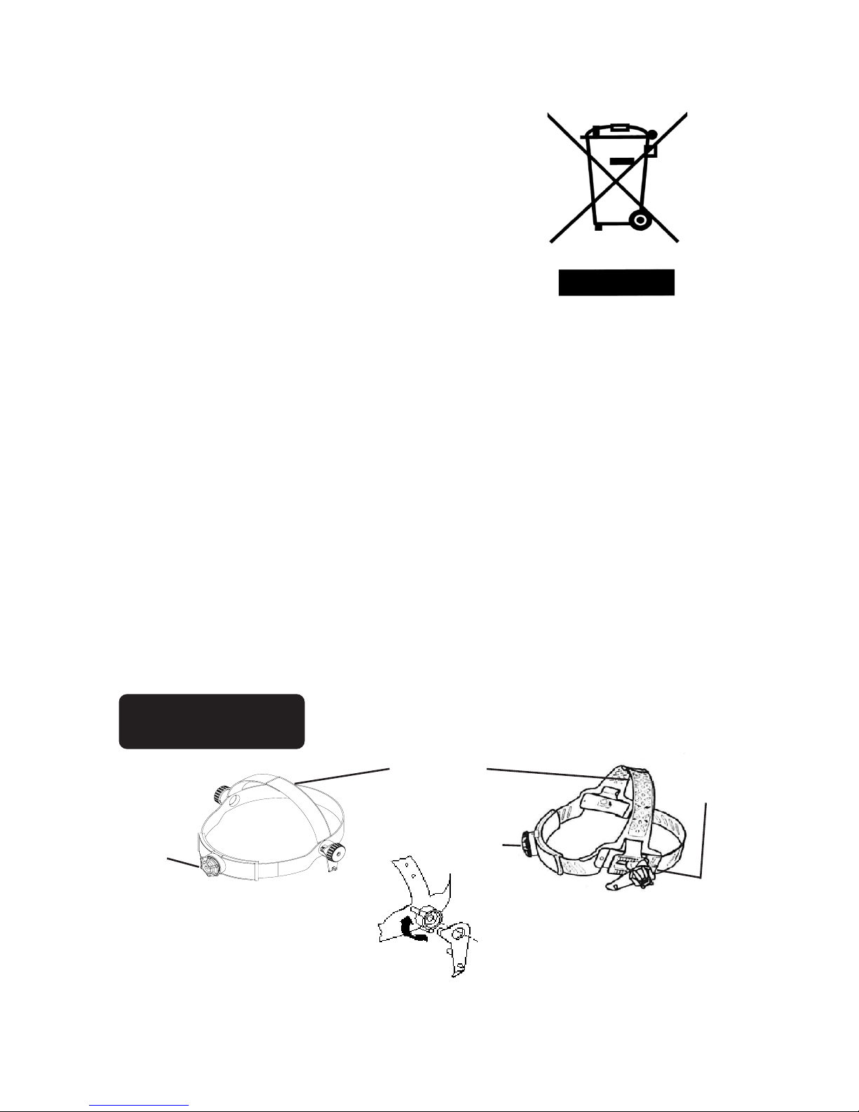
Welding Helmets:
Welding helmets are designed to provide protection against UV/IR radiation around the user's
face. ArcOne® welding helmets meet/exceed face coverage defined by CE standards. ArcOne®
welding helmets are suitable for arc welding. Refer to any or all of the following standards for
more specifications: ANSI Z87, CAN/CSA Z94.3, and CE EN 166 & 175.
CAUTION: not meant to protect against Severe Impact, explosives, fragments from grinding
wheels, abrasive discs, and hazardous fluids. Use secondary impact protection, such as safety
glasses.
Figure 3a: LCD Readout
(5000V, 5500V, 5130V, 7000V,
and 7500V)
Figure 3c: LCD Readout
(iDF48)
- 3-
X-TIG
Figure 3b: LCD Readout
(5000VX, 5500VX, 5130VX,
7000VX, and 7500VX)

- 4-
Limitations of Use Continued
DO OT use this helmet without proper training from a certified welder or welding instructor.
DO OT use this helmet in an excessive heat environment where the operation of the filter
becomes non-functional due to exceeding the temperature ratings of the electronic components.
Care and Maintenance
NOTE: Replacement components must be used in accordance with these instructions.
Failure to use ArcOne®replacement components in accordance with these instructions
voids certification of this product.
Filters:
Filters require virtually no maintenance other than periodic cleaning when the lens, solar panel,
and/or sensor(s) become dirty or clouded from smoke. Dampen a soft cloth or paper towel with
window cleaner or a mild soapy solution and gently wipe clean (do not immerse in water or
solution). Change the cover plates frequently. Storage Temperature -10 - 38°C (14 - 100°F)
Models with a replaceable battery will need the battery changed periodically when the Low
Battery LED/LCD indicates.
Welding Helmets:
Welding helmets require virtually no maintenance other than periodic cleaning when dirty. Clean
your helmet by using a mild soapy solution and a soft cloth or paper towel (do not immerse in
water or solution).
DO OT throw or abuse the helmet. Doing so may crack the helmet shell and compromise the
protection.
Protection (Cover) Plates:
Change cover plates when they lose flexibility and/or become bowed or distorted. Clean with
mild soapy solution including any build-up from the area where the cover plate is retained.
Discard if cleaning fails to improve visibility or cracks, scratches, etc. impair visibility.
Storage:
Equipment may be stored in original packaging or similar packaging. Store in a safe and dry
location away from direct heat.
Spatter Protection
SPATTER DAMAGE IS NOT COVERED BY WARRANTY
Ensure that the helmet is always equipped with an Outside Cover Plate (in front of the filter, on
the outside of the helmet) and an Inside Cover Plate (behind the filter, on the inside of the
helmet). These cover plates must be replaced if broken, warped, damaged, or covered with
welding spatter such that vision is impaired. Replace regularly only with ArcOne®cover plates.
All helmets use 1 mm thic cover plates.

- 5-
Headgear
04-H
Includes sweatband (not shown)•
Height Adjustment (Snap Out/ Slide/ Snap In)•
Circumference Adjustment (Ratchet Push/Turn)•
Angle Adjustment (Pivot Stop)•
06-H
Includes sweatband (not shown)•
Height Adjustment (Snap Out/ Slide/ Snap In)•
Circumference Adjustment (Ratchet Push/Turn)•
Angle Adjustment (Pivot Stop)•
Horizontal Adjustment (Slide Forward)•
Ratchet
Knob
Ratchet
Knob
Height Adjustment
Pivot Stop
Horizontal
Adjustment
Information on Disposal for Users of Waste Electrical & Electronic
Equipment (WEEE)
For private household users in the European Union
The WEEE symbol on the product(s) and / or accompanying
documents (see Figure 4) means that used electrical and
electronic products should not be mixed with general
household waste. For proper treatment, recovery and
recycling, please take this product(s) to designated
collection points where it will be accepted free of charge.
Alternatively, in some countries you may be able to return
your products to your local retailer upon purchase of an
equivalent new product.
Disposing of this product correctly will help save valuable
resources and prevent any potential negative effects on
human health and the environment, which could otherwise
arise from inappropriate waste handling.
Please contact your local authority for further details of your nearest designated collection point.
Penalties may be applicable for incorrect disposal of this waste, in accordance with national
legislation.
For business users in the European Union
Please contact your dealer or supplier for information on the proper methods to discard your
electrical and electronic equipment.
Information on Disposal in other Countries outside the European Union
This symbol is only valid in the European Union. Please contact your local authorities or dealer
and ask for the correct method of disposal.
Parts Selection Guide
Figure 4: WEEE Symbol

- 6-
VISIO ®
06-H
06-H SB
Inside Cover Plate
(see Table 1)*
Auto-Darkening
Filter
V-911-S
Vision 90x110 Shell
04-OP
Optional Mag Lens, VML-XXX, Where
XXX=Diopter number (Not shown)
CARRERATM ArcOne®
*Optional Mag Lens, VML-XXX, Where
XXX=Diopter number (Not shown)
Inside Cover Plate
(see Table 1)* 04-OP Outside
Cover Plate
Auto-Darkening
Filter
CARRERA-911-S
Helmet Shell
CARRERA SCREW
(3X16mm)
(Not shown)
04-H Headgear Assembly
(Sweatband Included)

- 7-
Cover Plate Instructions:
With notches facing up, slide one side of
cover plate into guide clip. Align notches
and push other side of cover plate into
guide clip. Cover plate will click into place.
Center Section Instructions:
Slide A-D filter and inside cover plate into
Filter Holder. Slide notches on top of Filter
Holder into slots on helmet. Line up Filter
Holder with Centering Pin on helmet, squeeze
tabs on Filter Holder and push into tab slots.
Release tabs into bottom catches.
Slots
Centering
Pin
Bottom
Catch
PYTHO ®
06-H
06-H SB
Inside Cover Plate
(see Table 1)*
Auto-Darkening Filter
PYTHON-911-S
Python 90x110 Shell
PYTHON01-911-CP
Python 90x110 Cover Plate
PYTHON01-911-CS
Python 90x110 Center Section
uide Clip
PYTHON01-911-CP
Python 90 X 110 Cover Plate
*Optional Mag Lens,
VML-XXX, Where
XXX=Diopter number
(Not shown)

- 8-
1000FcF 1500V 2000V 2500V 4000V 4500V iDF48
Viewing Area 3864 mm2
(6.0 sq in)
3864 mm2
(6.0 sq in)
4704 mm2
(7.3 sq in)
4704 mm2
(7.3 sq in)
4500 mm2
(7.0 sq in)
4500 mm2
(7.0 sq in)
4608 mm2
(7.1 sq in)
Filter Size 90x110 mm 90x110 mm 90x110 mm 90x110 mm 90x110 mm 90x110 mm 90x110 mm
ARC
Sensing
Two
sensors
Two
sensors
Two
sensors
Two
sensors
Four
sensors
Four
sensors
Two
ensors
Sensitivity
Control
Analog:
Variable
Analog:
Variable
Analog:
Variable
Analog:
Variable
Analog:
Variable
Digital:
Variable
Digital:
Variable
Switc ing
Time
(seconds)
1/10,000
(0.1 msec)
5/10,000
(0.5 msec)
5/10,000
(0.5 msec)
1/10,000
(0.1 msec)
1/10,000
(0.1 msec)
1/10,000
(0.1 msec)
1/10,000
(0.1 msec)
Primary
Power olar Cells olar Cells olar Cells olar Cells
Lithium
Battery &
olar Cells
Lithium
Battery &
olar Cells
AA
Battery &
olar Cells
Back-up
Power
Lithium
Battery
Lithium
Battery
Lithium
Battery
Lithium
Battery
Lithium
Battery
Lithium
Battery
Lithium
Battery
Operating
Temp.
-10-55C
(14-131F)
-10-55C
(14-131F)
-10-55C
(14-131F)
-10-55C
(14-131F)
-10-55C
(14-131F)
-10-55C
(14-131F)
-10-55C
(14-131F)
Storage
Temp.
-10-38C
(14-100F)
-10-38C
(14-100F)
-10-38C
(14-100F)
-10-38C
(14-100F)
-10-38C
(14-100F)
-10-38C
(14-100F)
-10-38C
(14-100F)
UV / IR
Protection
Up to hade
16
Up to hade
16
Up to hade
16
Up to hade
16
Up to hade
16
Up to hade
16
Up to hade
16
Dark to Lig t
Delay
0.2- 2
seconds
0.2-2
seconds
0.2-2
seconds
0.2-2
seconds
0.1-2
seconds
0.1-2
seconds
0.1-3.5
seconds
Lig t S ade 4444444
Dark S ade 9-13 9-13 9-13 9-13 9-13 9-13 5-8/9-13
Grind Mode Yes No No No Yes Yes Yes
Intelligent
Auto-S ade
Mode
No No No No No No Yes
Intelligent
TIG Mode No No No No No No Yes
Enclosure
Integrity
Not Dust/Water
Resistant
Not Dust/Water
Resistant
Not Dust/Water
Resistant
Not Dust/Water
Resistant
Not Dust/Water
Resistant
Not Dust/Water
Resistant
Dust/Water
Resistant
Standards 4CE EN379 4CE EN379 4CE EN379 4CE EN379 4CE EN379 2CE EN379 2CE EN379
Optical Class 1111111
Diffusion of
Lig t Class 2222111
Variation in
Luminous
Transmit-
tance Class
1111111
Angle
Dependency
Class
3333222
Inside Cover
Plate Part
Numbers 03-OP 09-IP 03-OP 03-OP 03-OP 03-OP 04-OP
Table 1. Filter Specifications

- 9-
5000V &
5000VX*
5130V &
5130VX*
5500V &
5500VX* 6000VI4 7000V &
7000VX*
7500V &
7500VX*
Viewing Area 4608 mm2
(7.1 sq in)
4608 mm2
(7.1 sq in)
4608 mm2
(7.1 sq in)
8100 mm2
(12.5 sq in)
5684 mm2
(8.8 sq in)
5684 mm2
(8.8 sq in)
Filter Size 90x110 mm 90x110 mm 90x110 mm 90x110 mm 90x110 mm 90x110 mm
ARC
Sensing
Two
sensors
Two
sensors
Two
sensors
Four
ensors
Two
sensors
Two
sensors
Sensitivity
Control
Digital:
Variable
Digital:
Variable
Digital:
Variable
Analog:
Variable
Digital:
Variable
Digital:
Variable
Switc ing
Time
(seconds)
1/10,000
(0.1 msec)
1/10,000
(0.1 msec)
1/10,000
(0.1 msec)
1/10,000
(0.1 msec)
1/10,000
(0.1 msec)
1/10,000
(0.1 msec)
Primary Power olar Cells olar Cells olar Cells Lithium
Battery olar Cells olar Cells
Back-up Power Lithium
Battery
Lithium
Battery
Lithium
Battery None Lithium
Battery
Lithium
Battery
Operating
Temp.
-10-55C
(14-131F)
-10-55C
(14-131F)
-10-55C
(14-131F)
-10-55C
(14-131F)
-5-55C
(23-131F)
-5-55C
(23-131F)
Storage Temp. -10-38C
(14-100F)
-10-38C
(14-100F)
-10-38C
(14-100F)
-10-38C
(14-100F)
-10-38C
(14-100F)
-10-38C
(14-100F)
UV / IR
Protection Up to hade 16 Up to hade 16 Up to hade 16 Up to hade 16 Up to hade 16 Up to hade 16
Dark to Lig t
Delay
0.1-3.5
seconds
0.1-3.5
seconds
0.1-3.5
seconds
0.1 or 2
seconds
0.1-3.5
seconds
0.1-3.5
seconds
Lig t S ade 4 4 4 4 4 4
Dark S ade 9-13 5-9/9-13 9-13 9-13 5-9/9-13 5-9/9-13
Grind “Mode” Yes Yes Yes Yes Yes Yes
Intelligent
Auto-S ade
“Mode”
No No No No No No
Intelligent
TIG “Mode” No No No No No No
Enclosure
Integrity
Dust / Water
Resistant
Dust / Water
Resistant
Dust / Water
Resistant
Dust / Water
Resistant
Dust / Water
Resistant
Dust / Water
Resistant
Standards 2CE EN379 4CE EN379 2CE EN379 1CE EN379 4CE EN379 4CE EN379
Optical Class 111111
Diffusion of
Lig t Class 1 1 1 2 1 1
Variation in
Luminous
Transmittance
Class
111111
Angle
Dependency
Class
2 2 2 1 1 1
Inside Cover
Plate Part
Numbers 04-OP 04-OP 04-OP 04-OP 10-IP 10-IP
Table 1. Filter Specifications (cont.)
*Filter variants designated with (X) have X-TI “Mode” at the highest sensitivity setting. See Sensitivity
Adjustment section for details.

Significance of Markings:
Welding Filters:
Examples: 4 / 5-8/9<13 AR M 1/1/1/2 EN379
4/ 5-9/9-13 AR 1/1/1/2 EN379
4 – Light Shade number
5-8 or 5-9 – Dark Shade range 1
9<13 – Dark Shade range 2 (Auto-Variable “Mode”)
9-13 – Dark Shade range 2 (Manual-Variable “Mode”)
AR – Manufacturers mark
M – Auto Variable
1 – Optical Class
1 – Diffusion of Light Class
1 – Variation in Luminous Transmittance class
2 – Angle Dependency class (This is a new classification of EN379. This marking may not be
indicated on older models.)
Welding Helmets:
Significance of CE Markings:
Example: AR EN 175 -F CE
AR – Company Identification Mark
EN 175 – CE Welding Helmet Standard
-F – Impact Class (Low Energy)
CE – European Mark
Significance of Other Markings:
Example: AR Z87
AR – Company Identification Mark
Z87 – ANSI Standard for Eye and Face Protectors
Example: CAN/CSA Z94.3 Labs
CAN/CSA Z94.3 – CSA Standard for Eye and Face Protectors
Labs – CAN/CSA Certified Lab
Product Certification Bodies
1This “Model” has been certified by: Certottica SCARL
Zona Industriale Villanova
32013 Longarone (BL), Italy
Notified Body Number: 0530
2This “Model” has been certified by: ECS mbH
Obere BahnstraBe 25
73431 Aelen - ermany
Notified Body Number: 1883
3This “Model” has been certified by: INSPEC International
56 Leslie Hough Way
Salford
reater Manchester
M6 6AJ, England
Notified Body Number: 0194
4This “Model” has been certified by: DIN CERTCO
Alboinstrasse 56
12103 Berlin, ermany
Notified Body Number: 0196
*indicates pending certification
- 10 -

-11-
SERIAL NUMBER
Serial Number is located
on the top of the filter.
Slide A-D Filter out from
under Retention Spring.
Serial Number
SERIAL NUMBER
Filter Removal Diagram
Table 2: Shade Selection Guide
CE Shade selection uide
L67-4301 Rev 01 20181031
Other manuals for 1000FcF
1
This manual suits for next models
12
Table of contents
Other ArcOne Welding Accessories manuals
Popular Welding Accessories manuals by other brands

Kempi
Kempi SuperSnake GT02S operating manual

Elektra Beckum
Elektra Beckum Welding Transformers and Rectifiers SB 160 C operating instructions

Miller Electric
Miller Electric MIGmatic M-10 Brochure & specs

Triton Electronics
Triton Electronics AMV 300 manual

jbc
jbc PA120 instruction manual

Parweld
Parweld XR937H User instructions