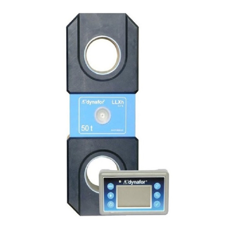
Evers dynafor LLZS Series Manual

FR
GB
NL
DE
ES
IT
PT
NO
SE
FI
DK
PL
Français
English
Nederlands
Deutsch
Español
Italiano
Português
Norsk
Svenska
Suomi
Dansk
Polski
w
Instructions d’emploi
et d’entretien
Operating and maintenance
instructions
Instructies voor gebruik
en onderhoud
Gebrauchs-
und Wartungsanleitung
Manual de empleo
y de mantenimiento
Istruzioni per l’uso
e la manutenzione
Instruções de uso
e de manutenção
Vedlikeholds-
og bruksanvisning
Instruktionsbok för
användning och underhåll
Käyttö- ja huoltokäsikirja
Brugs- og
vedligeholdelsesvejledning
Instrukcja obsługi
i konserwacji
1 t / 3.2 t / 6.3 t / 12.5 t / 20 t
Dynamomètres électroniques série LLZ2
LLZS series electronic dynamometers
Elektronische dynamometers serie LLZ2
LLZ2 Elektronische Zugkraft-Messgeräte
Dinamómetros electrónicos serie LLZ2
Dinamometri elettronici serie LLZ2
Dinamómetros eletrónicos série LLZ2
Elektroniske dynamometre serie LLZ2
Elektroniska dynamometrar ur LLZ2 serien
Elektroniset dynamometrit, sarja LLZ2
Elektroniske dynamometre serie LLZ2
Dynamometry elektroniczne serii LLZ2
Heben • Sichern • Fördern • Verpacken
Evers GmbH • Graf-Zeppelin-Straße 10-12 • 46149 Oberhausen • Telefon (02 08) 99475-0 • Telefax (02 08) 99 475-31 • E-Mail evers@eversgmbh.de • www.eversgmbh.de

2
Fig. / g. / afb. / abb. / g. / g. / g. / g. / g. / kuva / g. / rys.
1
I
J
K
A
B
H
G
F
E
D
C
L
M
N
2
J
Heben • Sichern • Fördern • Verpacken
Evers GmbH • Graf-Zeppelin-Straße 10-12 • 46149 Oberhausen • Telefon (02 08) 99475-0 • Telefax (02 08) 99 475-31 • E-Mail evers@eversgmbh.de • www.eversgmbh.de

3
3
H
C
B
A
D
G
E
F
0.3%
dynafor™
LLZ2
T
Heben • Sichern • Fördern • Verpacken
Evers GmbH • Graf-Zeppelin-Straße 10-12 • 46149 Oberhausen • Telefon (02 08) 99475-0 • Telefax (02 08) 99 475-31 • E-Mail evers@eversgmbh.de • www.eversgmbh.de

4
Fig. / g. / afb. / abb. / g. / g. / g. / g. / g. / kuva / g. / rys.
4
E
A
D
C
B
5
Type / type / type / typ / tipo / tipo / tipo / type / typ / tyyppi / type / typ A
A
D
C
F
E
B
H
G
I
Heben • Sichern • Fördern • Verpacken
Evers GmbH • Graf-Zeppelin-Straße 10-12 • 46149 Oberhausen • Telefon (02 08) 99475-0 • Telefax (02 08) 99 475-31 • E-Mail evers@eversgmbh.de • www.eversgmbh.de

5
5
Type / type / type / typ / tipo / tipo / tipo / type / typ / tyyppi / type / typ B
G
H
I
A
D
B
E
F
C
5
Type / type / type / typ / tipo / tipo / tipo / type / typ / tyyppi / type / typ C
A
D
B
C
F
E
H
I
G
Heben • Sichern • Fördern • Verpacken
Evers GmbH • Graf-Zeppelin-Straße 10-12 • 46149 Oberhausen • Telefon (02 08) 99475-0 • Telefax (02 08) 99 475-31 • E-Mail evers@eversgmbh.de • www.eversgmbh.de

6
Fig. / g. / afb. / abb. / g. / g. / g. / g. / g. / kuva / g. / rys.
6
0.3%
dynafor
™
LLZ2
T
0.3%
dynafor
™
LLZ2
T
0.3%
dynafor
™
LLZ2
T
0.3%
dy na for
™
LLZ2
T
0.3%
dynafor
™
LLZ2
T
7
T
T1 T2 T3
ABCDE
8
T
T1 T2 T3
AB
CD
2’’
2’’
T2 T2
Heben • Sichern • Fördern • Verpacken
Evers GmbH • Graf-Zeppelin-Straße 10-12 • 46149 Oberhausen • Telefon (02 08) 99475-0 • Telefax (02 08) 99 475-31 • E-Mail evers@eversgmbh.de • www.eversgmbh.de

7
9
T
T1 T2 T3
AB
CD
T3 T3
10
T
T1 T2 T3
ABC
11
T
T1 T2 T3
AB
2’’
T2
2’’
Heben • Sichern • Fördern • Verpacken
Evers GmbH • Graf-Zeppelin-Straße 10-12 • 46149 Oberhausen • Telefon (02 08) 99475-0 • Telefax (02 08) 99 475-31 • E-Mail evers@eversgmbh.de • www.eversgmbh.de

17
GB
Contents Page
Priority recommendations����������������������������������������������������������������������������������������������������18
Denitions and icons������������������������������������������������������������������������������������������������������������19
1� Presentation�����������������������������������������������������������������������������������������������������������������������20
2. Operating principle �����������������������������������������������������������������������������������������������������������20
3. Description and marking ��������������������������������������������������������������������������������������������������20
4. Applicable standards and regulations ����������������������������������������������������������������������������20
5. Technical specications ���������������������������������������������������������������������������������������������������21
5.1. Sensor and display unit���������������������������������������������������������������������������������������������������� 21
5.2. Optional Accessories�������������������������������������������������������������������������������������������������������� 22
5.2.1. Shackles�������������������������������������������������������������������������������������������������������������������������������22
5.2.2. Swivel hooks ������������������������������������������������������������������������������������������������������������������������22
6. Installation, use and uninstall������������������������������������������������������������������������������������������22
6�1� Installation ������������������������������������������������������������������������������������������������������������������������� 22
6�2� Operation ��������������������������������������������������������������������������������������������������������������������������� 22
6�3� Uninstalling������������������������������������������������������������������������������������������������������������������������ 22
6.4. Prohibition of use�������������������������������������������������������������������������������������������������������������� 23
7. Overload indication�����������������������������������������������������������������������������������������������������������23
8� Commissioning �����������������������������������������������������������������������������������������������������������������23
8.1. Inserting the batteries.������������������������������������������������������������������������������������������������������ 23
8.2. Turning on the device ������������������������������������������������������������������������������������������������������� 23
8.3. Automatic reset ����������������������������������������������������������������������������������������������������������������� 23
9. Functions ���������������������������������������������������������������������������������������������������������������������������24
9.1. Tare function���������������������������������������������������������������������������������������������������������������������� 24
9.2. Peak load function ������������������������������������������������������������������������������������������������������������ 24
9.3. Changing units ������������������������������������������������������������������������������������������������������������������ 24
9�4� Stop ������������������������������������������������������������������������������������������������������������������������������������ 24
10. Battery Replacement�������������������������������������������������������������������������������������������������������24
11. Regulatory audit ��������������������������������������������������������������������������������������������������������������25
12. Maintenance���������������������������������������������������������������������������������������������������������������������25
13. Storage, transportation, disposal����������������������������������������������������������������������������������25
14. Malfunctions and troubleshooting ��������������������������������������������������������������������������������25
15. Standard certicate (specimen)�������������������������������������������������������������������������������������25
Heben • Sichern • Fördern • Verpacken
Evers GmbH • Graf-Zeppelin-Straße 10-12 • 46149 Oberhausen • Telefon (02 08) 99475-0 • Telefax (02 08) 99 475-31 • E-Mail evers@eversgmbh.de • www.eversgmbh.de

18
GB
PRIORITY RECOMMENDATIONS
1� Before installing and operating this device, it is essential, for its safety and effectiveness, to be aware of this
manual and comply with its requirements. A copy of this manual should be made available to every operator.
Additional copies can be supplied on request.
2� Do not use this product if one of the labels attached to the device, or any of its accessories, or if one of the
inscriptions shown on it, as shown at the end of this manual, are no longer there or no longer legible. Identical
labels can be provided on request and must be in place before continuing the use of the device.
3� Ensure that any person to whom you entrust the use of this device knows how to handle it and is able to fulll the
safety requirements that such handling requires for the job in question. This manual must be made available to all
users. Protect your equipment from any unsupervised operation.
4� The set up and commissioning of this device must be carried out under conditions ensuring the safety of the
installer, in compliance with applicable regulations.
5� Before each use of the device, check that it is in apparent good condition, as well as the accessories used with
the device. Never use a lift table which is not visibly in good physical condition. Return it to the manufacturer for
review if it reveals malfunctions not related to the batteries.
6� Protect the device from impacts, especially on the display unit.
7� The unit must never be used for any operations other than those described in this manual. It should never be used
for a load greater than the maximum working capacity indicated on the device. The table must never be used in
an explosive atmosphere.
8� This device should not be used in a lifting line used for people without the user having checked the application of
the duty cycles required for the safety of people, and more generally the implementation of the safety regulations
applicable to the load line in which it is interposed.
9� Tractel® denies all responsibility for the operation of this device in an assembly conguration not described in
this manual.
10� Any modication of the device beyond the control of Tractel®, or removal of any component part will exonerate
Tractel® from all liability.
11� Any dismantling of this device not described in this manual, or repairs made outside the control of Tractel® will
exonerate Tractel® from all liability, especially in case of replacement of original parts with parts from elsewhere.
12� As the dynafor™ dynamometer is a lifting accessory, the safety regulations applicable to this category of
equipment must be observed.
13� In the event of termination of use, store the redundant device in conditions prohibiting its use. Comply with
regulations on environmental protection.
14� Certied in compliance with European regulations, this unit must be checked to ensure compliance with the
regulations of any other country where it may be used prior to being commissioned there. Comply with this
regulation.
Heben • Sichern • Fördern • Verpacken
Evers GmbH • Graf-Zeppelin-Straße 10-12 • 46149 Oberhausen • Telefon (02 08) 99475-0 • Telefax (02 08) 99 475-31 • E-Mail evers@eversgmbh.de • www.eversgmbh.de

19
GB
DEFINITIONS AND ICONS
Denitions:
In this manual, the following terms mean:
“Product”: Component or assembly of equipment as dened on the rst page that comes complete , or in the
different models described.
“Installation”: Set of all the necessary operations to prepare the complete assembly for commissioning (or connection
to other components for commissioning), from the state in which it was delivered.
“User”: Person or department responsible for the management and safe use of the product described in the manual.
“Technician”: Qualied person in charge of the maintenance operations described and permitted to the user, who is
competent and familiar with the product, by the manual.
“Operator”: Person or department using the product in compliance with the purpose for which it is intended.
“EM”: Measuring range (full scale).
“MWC” Maximum Working Capacity.
Icons used in these instructions:
“DANGER”: Comments intended to prevent harm to people; including mild, severe or even fatal injuries, and
environmental damage.
“IMPORTANT”: Comments intended to prevent failure, or damage to the device, but not directly endangering the
life or health of the operator or others, or causing environmental damage.
“NOTE”: Comments regarding precautions to be followed for efcient and convenient use and maintenance
of an installation.
: Reading the instruction and maintenance required.
Heben • Sichern • Fördern • Verpacken
Evers GmbH • Graf-Zeppelin-Straße 10-12 • 46149 Oberhausen • Telefon (02 08) 99475-0 • Telefax (02 08) 99 475-31 • E-Mail evers@eversgmbh.de • www.eversgmbh.de

20
GB
1� PRESENTATION
dynafor™ LLZ2 dynamometers are precision stress sensors (0.3% FS) for measuring dynamic stress and indicating
loads. The capacity range is from 1 t to 20 t.
The equipment is supplied with batteries in a suitcase containing:
a) The LLZ2 dynamometer.
b) A usage and maintenance instruction manual.
c) An adjustment certicate.
d) An EC declaration of conformity.
2� OPERATING PRINCIPLE
The operating principle of the dynafor™ LLZ2 is based on measurement using strain and elongation gauges, within
its elastic limit, of a metal body subjected to traction stresses.
The device operates in all directions.
An electrical signal proportional to the load is generated by the strain gauges built into the sensor. This signal is
processed by a microprocessor analyser before being displayed on the LCD screen built into the device.
3� DESCRIPTION AND MARKING
See Figure 1
AModel
BSerial No.:
CCapacity
DPrecision
ET3 Peak Load Button
FT2 Tare Button
GT1 On/Off Button
HProduct Brand
ISensor body
JHole for shackle
KLCD screen
LManufacturer's Name
MBattery compartment cover
NM lid xing screws
"NOTE": All indications and labels afxed by the manufacturer on the product must be kept fully legible. In
case of loss or damage, replace these indications and labels before continuing to use the device.
Tractel® can provide new labeling media on request.
4� APPLICABLE STANDARDS AND REGULATIONS
• European directive: 2006/42/EC
• EMC Directive: 2004/108/CE
Heben • Sichern • Fördern • Verpacken
Evers GmbH • Graf-Zeppelin-Straße 10-12 • 46149 Oberhausen • Telefon (02 08) 99475-0 • Telefax (02 08) 99 475-31 • E-Mail evers@eversgmbh.de • www.eversgmbh.de

21
GB
5� TECHNICAL SPECIFICATIONS
5�1� Sensor and display unit
See Figure 2
AMeasuring value
BSign of the measurement
CNET indicator (Net Value of the measurement)
DGROSS indicator (Gross Value of measurement)
EPeak load indicator
FBattery indicator
GLbs unit indicator
HKg unit indicator
IdaN unit indicator
JDecimal point
See Figure 3
MODEL LLZ2
1 t
LLZ2
3�2 t
LLZ2
6�3 t
LLZ2
12�5 t
LLZ2
20 t
Maximum working
capacity t1 3�2 6�3 12�5 20
Trial load t 1�5 4�8 9�6 18�75 30
Safety factor > 4
Precision +/- % 0.3% EM
+/- kg 3 9�6 18�9 37�5 60
Increment kg 1 5 10 20 50
Maximum Display % 110% of MWC
Conversion Factor 1 kg = 0.98083 2.20462 daN = lbs
Dynamic effects lter by sliding average calculation in 2 seconds
Digit height mm 17�8
Autonomy h 250
Weight kg 0�75 0�93 1�44 3�22 5�1
IP protection IP 65
Working T° From -20°C to +50°C
Sensor Equipment Aluminium
Measurements in mm A 191 191 236 277 342
B 164 164 184 226 264
C 22 22 28 42 54
D83�5 99�5 121�5 120�5 147
E 22 22 22 45 45
F 19�8 19�8 19�8 40�5 40�5
G 36�4 36�4 36�4 59�4 59�4
H 37�6 44�8 54�7 60 73�5
Heben • Sichern • Fördern • Verpacken
Evers GmbH • Graf-Zeppelin-Straße 10-12 • 46149 Oberhausen • Telefon (02 08) 99475-0 • Telefax (02 08) 99 475-31 • E-Mail evers@eversgmbh.de • www.eversgmbh.de

22
GB
5�2� Optional Accessories
5�2�1� Shackles
To install dynafor™LLZ2 in a traction line, every shackle in compliance with applicable legislation may be used
provided that it complies with the maximum working capacity of dynafor™LLZ2.
See Figure 4
MWC
LLZ2
Shackle
MWC
A
mm
B
mm
C
mm
D
mm
E
mm kg
1 t and 3.2 t 3.25 t 42 16 60 20 27 0�6
6.3 t 6.5 t 58 22 84 25 37 1�4
12.5 t 13.5 t 89 35 132 38 57 4�4
20 t 25 t 110 50 178 50 73 14
5�2�2� Swivel hooks
The dynafor™LLZ2 can be tted with swivel hooks that facilitate the fastening of loads.
See Figure 5
LLZ2 Type A B C D E F G H I kg
1 t and 3.2 t A 26 33 185 20 32 49 118 43 23 3�2
6.3 t B 33 48 277�5 25 50 74 166 70 35 9�6
12.5 t C 60 70 320�5 41 58 80 213 85 42�5 17�4
20 t C 72 86 387 50 76 104 270 110 55 31�5
6� INSTALLATION, USE AND UNINSTALL
"DANGER": Product adjustment must only be performed by a qualied technician. The User shall ensure that
the operator has taken note of this instruction, usage and maintenance manual before using the
device.
6�1� Installation
During installation you must:
a) ensure adequate resistance of the anchorage points of the load line in relation to the force that will be applied.
b) ensure the compatibility of anchoring accessories both ends of the dynamometer and compliance with
applicable regulations.
c) properly lock the shackles, by tightening their pin to the limit and ensure the presence and good working of
the safety latch hook.
d) respect the alignment of the sensor in the force line.
6�2� Operation
Use dynafor™LLZ2 only in traction.
The device can be used in all directions including horizontally.
The dynafor™LLZ2 operates correctly in a temperature range of -20 °C to +50 °C. For use beyond these
temperatures, you must provide a thermal protection device.
See Figure 6
6�3� Uninstalling
When uninstalling the device, rst make sure that any tractive strain has been eliminated.
Heben • Sichern • Fördern • Verpacken
Evers GmbH • Graf-Zeppelin-Straße 10-12 • 46149 Oberhausen • Telefon (02 08) 99475-0 • Telefax (02 08) 99 475-31 • E-Mail evers@eversgmbh.de • www.eversgmbh.de

23
GB
6�4� Prohibition of use
IT IS FORBIDDEN:
• To use the dynafor™LLZ2 in a lift line for people without having run a specic risk analysis.
• To modify the device body by machining, drilling or other methods.
• To use the dynafor™ beyond their MWC.
• To carry out arc welding with the dynamometer in the earth circuit.
• To disassemble or open the sensor.
• To use the device for operations other than those described in this manual.
• To use the sensor if there is danger of being subjected to loads in compression, bending or twisting.
• To use the sensor in a highly corrosive environment.
• To use the sensor out of the temperature range of -20°C to 50°C.
• To use the sensor if it has been subject to a load greater than 110% of the MWC.
7� OVERLOAD INDICATION
When the load applied to the sensor exceeds the maximum capacity of 10%
of device (e.g. a 1 t loaded at 1.1 t) the display unit indicates an overload
status message “– HI –” as shown opposite.
“DANGER”:
In case of overload it is imperative to completely release the stress on the sensor
and check the reset of the device.
If the device indicates a stress value when it is unsolicited, it has undergone a
permanent deformation. In this case, it is imperative to check the device by the
manufacturer before further use.
8� COMMISSIONING
8�1� Inserting the batteries.
2 × 1.5 V “AAA” were installed at the factory.
Remove the insulating tab protruding from the battery compartment to activate them.
For future replacement of the batteries, refer to Chapter 10�
8�2� Turning on the device
See Figure 7
Item Description
ADigit check
BCapacity
CVersion of the program
D Date of last calibration (mm.yy)
ECurrent measurement
8�3� Automatic reset
At the start of dynafor™ LLZ2, the display will show “0” as long as the force measured is less than 10% of the MWC
of the device.
Heben • Sichern • Fördern • Verpacken
Evers GmbH • Graf-Zeppelin-Straße 10-12 • 46149 Oberhausen • Telefon (02 08) 99475-0 • Telefax (02 08) 99 475-31 • E-Mail evers@eversgmbh.de • www.eversgmbh.de

24
GB
9� FUNCTIONS
9�1� Tare function
See Figure 8
Item Description
AWeight with accessories
BTare completed
CLift a load. = Net weight
D 1 pulse Net Weight <> Gross weight
Note: When the tare function is enabled, a load reduction can optionally switch the display to negative.
9�2� Peak load function
See Figure 9
Item Description
ACurrent measurement
BActivating the Peak Load function
CThe peak value of the measurement remains displayed
D Disabling the Peak Load function
Notes:
• The tare function is available in Peak Load mode.
• In peak load mode, the reading frequency shifts from 3 Hz to 32 Hz.
9�3� Changing units
See Figure 10
Press and maintain T3 to scroll through the units, releasing T3 to select the unit.
9�4� Stop
See Figure 11
Item Description
ACurrent measurement
BComplete shutdown of the device
Note: If it is not requested, the unit will automatically turn off after 20 minutes.
10� BATTERY REPLACEMENT
The battery indicator ashes when they are discharged. Then proceed to their replacement.
• Using a Phillips screwdriver, remove the battery box cover.
• Replace the 2 1.5 V batteries “AAA” with new batteries, checking polarity.
• Replace the battery cover and tighten the screws so that the cover is ush with the edge of the battery case.
Heben • Sichern • Fördern • Verpacken
Evers GmbH • Graf-Zeppelin-Straße 10-12 • 46149 Oberhausen • Telefon (02 08) 99475-0 • Telefax (02 08) 99 475-31 • E-Mail evers@eversgmbh.de • www.eversgmbh.de

25
GB
11� REGULATORY AUDIT
New devices are delivered with a certicate of adjustment. This document indicates the values obtained during
adjustment and certies that the sensor has been adjusted, following an internal procedure, on a calibration bench
on which a standard sensor is connected to the international standard calibration.
Tractel® recommends an annual metrological check of each device.
12� MAINTENANCE
The dynafor™ LLZ2 requires no maintenance except regular cleaning with a dry cloth.
13� STORAGE, TRANSPORTATION, DISPOSAL
Storage: put the device in its original packaging, after having removed the batteries from the sensor. Store in a cool,
dry place.
Transport: transport the device in its original packaging.
Disposal: Any disposal of the device must be carried out in accordance with the regulations in force in the country
of use. For countries subject to European regulations, it should be noted that the dynamometers are not within
directives “DEEE” and “RoHS”.
14� MALFUNCTIONS AND TROUBLESHOOTING
Anomalies Possible causes Corrective actions
No reset
Tare Function enabled. Disable Tare function and display
the strain value “GROSS”.
Permanent deformation of the
sensor due to operator error;
excessive overload or under
compression.
The device must be checked by the
manufacturer before further use.
The sensor does not light Discharged batteries. Replace the batteries.
Electronics defective. Contact the after-sales service.
No changes in the display or
inconsistent display.
Malfunction of sensor or electronic
sound.
Reset: Turn off the sensor then
turn on.
In case of persistent malfunction,
contact customer service
Problem of linearity or precision. Malfunction of the sensor or its
electronics. Contact the after-sales service.
Sensor undergoing stress in
compression or torsion.
Eliminate the compressive force on
the sensor.
Negative imbalance of gauge
bridge. Contact the after-sales service.
15� STANDARD CERTIFICATE (SPECIMEN)
Heben • Sichern • Fördern • Verpacken
Evers GmbH • Graf-Zeppelin-Straße 10-12 • 46149 Oberhausen • Telefon (02 08) 99475-0 • Telefax (02 08) 99 475-31 • E-Mail evers@eversgmbh.de • www.eversgmbh.de

44
DE
Inhalt Seite
Wichtige Betriebsvorschriften ���������������������������������������������������������������������������������������������36
Denitionen und Piktogramme ��������������������������������������������������������������������������������������������37
1� Präsentation�����������������������������������������������������������������������������������������������������������������������38
2. Funktionsprinzip ���������������������������������������������������������������������������������������������������������������38
3. Beschreibung und Kennzeichnung���������������������������������������������������������������������������������38
4. Angewandte Bestimmungen:�������������������������������������������������������������������������������������������38
5. Technische Spezikationen����������������������������������������������������������������������������������������������39
5.1. Messgerät und Display����������������������������������������������������������������������������������������������������� 39
5.2. Optionales Zubehör ���������������������������������������������������������������������������������������������������������� 40
5.2.1. Schäkel ��������������������������������������������������������������������������������������������������������������������������������40
5.2.2. Drehbare Haken�������������������������������������������������������������������������������������������������������������������40
6. Installation, Benutzung und Demontage�������������������������������������������������������������������������40
6�1� Installation ������������������������������������������������������������������������������������������������������������������������� 40
6.2. Betrieb�������������������������������������������������������������������������������������������������������������������������������� 40
6�3� Demontage������������������������������������������������������������������������������������������������������������������������� 40
6.4. Ausschluss nicht bestimmungsgemäßer Verwendung������������������������������������������������� 41
7. Überlastanzeige�����������������������������������������������������������������������������������������������������������������41
8. Inbetriebnahme������������������������������������������������������������������������������������������������������������������41
8.1. Anbringung der Batterien������������������������������������������������������������������������������������������������� 41
8.2. Inbetriebnahme des Geräts���������������������������������������������������������������������������������������������� 41
8.3. Automatische Null������������������������������������������������������������������������������������������������������������� 41
9. Funktionen �������������������������������������������������������������������������������������������������������������������������42
9.1. Funktion Tara��������������������������������������������������������������������������������������������������������������������� 42
9.2. Funktion Spitzenwert�������������������������������������������������������������������������������������������������������� 42
9.3. Wechsel der Einheiten������������������������������������������������������������������������������������������������������ 42
9�4� Stopp ���������������������������������������������������������������������������������������������������������������������������������� 42
10. Austausch der Batterien�������������������������������������������������������������������������������������������������42
11. Vorschriftsmäßige Prüfung���������������������������������������������������������������������������������������������43
12. Wartung����������������������������������������������������������������������������������������������������������������������������43
13. Lagerung, Transport, Ausmusterung ����������������������������������������������������������������������������43
14. Störungsbeseitigung ������������������������������������������������������������������������������������������������������43
15. EG-Baumusterprüfbescheinigung (Muster)������������������������������������������������������������������43
Heben • Sichern • Fördern • Verpacken
Evers GmbH • Graf-Zeppelin-Straße 10-12 • 46149 Oberhausen • Telefon (02 08) 99475-0 • Telefax (02 08) 99 475-31 • E-Mail evers@eversgmbh.de • www.eversgmbh.de

45
DE
WICHTIGE BETRIEBSVORSCHRIFTEN
1� Vor der Installation und Benutzung dieses Geräts müssen Sie zur Gewährleistung der Betriebssicherheit und
einer optimalen Efzienz der Ausrüstung unbedingt die vorliegende Anleitung zur Kenntnis nehmen und die
darin enthaltenen Vorschriften einhalten. Ein Exemplar dieser Anleitung muss jedem Bediener des Geräts zur
Verfügung stehen. Auf Anfrage sind zusätzliche Exemplare erhältlich.
2� Benutzen Sie das Gerät nicht, wenn eines der am Ende dieser Anleitung aufgeführten am Gerät oder einem
Zubehör befestigten Etiketten oder deren Beschriftung fehlt oder nicht lesbar ist. Auf Anfrage sind identische
Etiketten erhältlich, die vor dem weiteren Betrieb des Geräts angebracht werden müssen.
3� Stellen Sie sicher, dass alle Personen, die Sie mit der Benutzung des Geräts beauftragen, mit dessen
Handhabung vertraut und in der Lage sind, die für den geplanten Einsatz geltenden Sicherheitsvorschriften
einzuhalten. Vorliegende Anleitung sollte Bedienern und Nutzern zur Verfügung gestellt werden. Schützen Sie
die Ausrüstung vor unbefugten Eingriffen.
4� Die Anbringung und Inbetriebnahme des Geräts muss unter Bedingungen erfolgen, die die Sicherheit des
Installateurs gemäß den geltenden Vorschriften garantieren.
5� Vor jeder Benutzung des Geräts müssen Sie sicherstellen, dass das Gerät sowie die damit verwendeten
Zubehörteile sichtbar in einwandfreiem Zustand sind. Niemals ein Gerät verwenden, das sichtbar nicht in
einwandfreiem Zustand ist. Bei nicht mit dem Zustand der Batterien zusammenhängenden Funktionsstörungen
muss das Gerät zur Überprüfung an den Hersteller geschickt werden.
6� Schützen Sie das Gerät und insbesondere die Anzeige vor Stößen aller Art.
7� Dieses Gerät darf nur für die Aufgaben eingesetzt werden, die in dieser Anleitung beschrieben sind. Es darf
nie für Lasten benutzt werden, die die auf dem Gerät angegebene Tragfähigkeit übersteigen. Es darf nicht in
explosionsgefährdeter Umgebung eingesetzt werden.
8� Das Gerät darf nur nach der Prüfung durch den Benutzer der Anwendung der Betriebskoefzienten
für die Personensicherheit und ganz allgemein der Einhaltung der für das Transportsystem geltenden
Sicherheitsbestimmungen in einem Personentransportsystem eingesetzt werden.
9� Tractel® lehnt jede Haftung für die Benutzung des Geräts in einer nicht in dieser Anleitung beschriebenen
Montagekonguration ab.
10� Jede Änderung des Geräts außerhalb der Kontrolle von Tractel® und jedes Entfernen eines Bauteils befreien die
Firma Tractel® von ihrer Haftung.
11� Jede nicht in dieser Anleitung beschriebene Demontage des Geräts bzw. jede Reparatur außerhalb der Kontrolle
von Tractel® befreit die Firma Tractel® von ihrer Haftung, insbesondere beim Ersatz von Originalteilen durch Teile
anderer Herkunft.
12� Da die dynafor™-Zugkraftmessgeräte Lastaufnahmemittel sind, müssen die für diese Ausrüstungskategorie
geltenden Sicherheitsbestimmungen eingehalten werden.
13� Bei einer endgültigen Außerbetriebnahme muss das Gerät so ausgemustert werden, dass seine Benutzung
unmöglich ist. Die Umweltschutzvorschriften beachten.
14� Dieser Apparat wurde entsprechend einer Europäischen Richtlinie zugelassen und muss vor jeder
Inbetriebnahme und jedem Einsatz auf seine Übereinstimmung mit den Richtlinien jedes anderen Landes
überprüft werden. Bei der Benutzung müssen diese Vorschriften eingehalten werden.
Heben • Sichern • Fördern • Verpacken
Evers GmbH • Graf-Zeppelin-Straße 10-12 • 46149 Oberhausen • Telefon (02 08) 99475-0 • Telefax (02 08) 99 475-31 • E-Mail evers@eversgmbh.de • www.eversgmbh.de

46
DE
DEFINITIONEN UND PIKTOGRAMME
Denitionen :
In dieser Anleitung haben die folgenden Begriffe diese Bedeutung:
„Produkt“: Auf dem Deckblatt deniertes Element oder Ausrüstungssystem, das vollständig in der Standardausführung
oder in Form eines der beschriebenen Modelle geliefert wird.
„Installation“ : Gesamtheit aller erforderlichen Maßnahmen, um das vollständige Produkt ausgehend vom
Lieferzustand in den Inbetriebnahmezustand (bzw. Bereitschaftszustand zur Verbindung mit anderen Elementen
zwecks Inbetriebnahme) zu bringen.
„Benutzer“ : Person oder Abteilung, die für die Verwaltung und Betriebssicherheit des in dieser Anleitung
beschriebenen Produkts verantwortlich ist.
„Techniker“ : Qualizierte Person, die für die in dieser Anleitung beschriebenen und dem Benutzer erlaubten
Wartungsarbeiten zuständig ist, und die sachkundig und mit dem Produkt vertraut ist.
„Bediener“ : Person oder Betriebsabteilung, welche das Produkt in Übereinstimmung mit dessen vorgesehenem
Einsatz benutzt.
„MB”: Messbereich (Endwert).
„Tragfähigkeit”: Maximale Tragfähigkeit.
In dieser Anleitung verwendete Piktogramme:
„GEFAHR“ : Kommentare zur Vermeidung von Personenschäden wie tödlichen, schweren oder leichten
Verletzungen, sowie zur Vermeidung von Umweltschäden.
„WICHTIG“ : Kommentare zur Vermeidung einer Störung oder Beschädigung des Produkts, die jedoch keine
direkte Gefahr für das Leben und die Gesundheit des Bedieners oder anderer Personen darstellen
oder einen Umweltschaden verursachen.
„HINWEIS“ : Kommentare hinsichtlich der erforderlichen Maßnahmen zur Gewährleistung einer efzienten
und zweckmäßigen Installation, Benutzung und Wartung.
: Das Lesen der Gebrauchs- und Wartungsanleitung ist obligatorisch.
Heben • Sichern • Fördern • Verpacken
Evers GmbH • Graf-Zeppelin-Straße 10-12 • 46149 Oberhausen • Telefon (02 08) 99475-0 • Telefax (02 08) 99 475-31 • E-Mail evers@eversgmbh.de • www.eversgmbh.de

47
DE
1� PRÄSENTATION
Die Zugkraftmessgeräte dynafor™ LLZ2 sind Präzisionsgeräte (± 0.3% vom Endwert) zur Messung von Zugkräften
und zur Lastanzeige. Der Messbereich der Produktreihe reicht von 1 t bis 20 t.
Das Gerät wird inklusive Batterien in einem Koffer mit folgendem Inhalt geliefert:
a) 1 Zugkraftmessgerät LLZ2.
b) 1 Gebrauchs- und Wartungsanleitung.
c) 1 Kalibrierbescheinigung.
d) 1 EG-Konformitätserklärung.
2� FUNKTIONSPRINZIP
dynafor™ LLZ2 Zugkraftmessgeräte arbeiten mit Dehnungsmessstreifen, welche die Verformung eines
Metallkörpers unter Zugbelastung messen.
Das Gerät funktioniert in allen Richtungen.
Die Dehnungsmessstreifen des Messgeräts erzeugen ein zur Last proportionales elektrisches Signal, welches von
einem Mikroprozessor verarbeitet und dann auf dem im Gerät integrierten LCD-Display angezeigt wird.
3� BESCHREIBUNG UND KENNZEICHNUNG
Siehe Abbildung 1
AModell
BSeriennummer
CFassungsvermögen
DPräzision
ET3 Spitzenwert-Taste
FT2 Tara-Taste
GT1 Ein/Aus-Taste
HMarke des Produkts
IMessgerätekörper
JSchäkelöffnung
KLCD-Display
LName des Herstellers
MDeckel des Batteriegehäuses
NBefestigungsschraube des Deckels M
„HINWEIS“: Alle vom Hersteller auf dem Produkt angebrachten Angaben und Etiketten müssen vollständig
vorhanden und lesbar sein. Fehlende oder beschädigte Angaben und Etiketten müssen vor der
weiteren Benutzung des Geräts ersetzt werden. Auf Anfrage sind neue Kennzeichnungen bei
Tractel® erhältlich.
4� ANGEWANDTE BESTIMMUNGEN:
• Europäische Richtlinie: 2006/42/EG
• EMV-Richtlinie: 2004/108/CE
Heben • Sichern • Fördern • Verpacken
Evers GmbH • Graf-Zeppelin-Straße 10-12 • 46149 Oberhausen • Telefon (02 08) 99475-0 • Telefax (02 08) 99 475-31 • E-Mail evers@eversgmbh.de • www.eversgmbh.de
This manual suits for next models
5
Table of contents
Languages:
Other Evers Measuring Instrument manuals
Popular Measuring Instrument manuals by other brands

Siemens
Siemens airanger DPL PLUS instruction manual
Sontex
Sontex Superstatic 789 installation guide

BlueTees
BlueTees 3 MAX+ user manual

PCB Piezotronics
PCB Piezotronics IMI SENSORS TO604B91 Installation and operating manual

Klein Tools
Klein Tools RT390 instruction manual
Murphy
Murphy PV485 installation manual
