Evers dynafor LLXh Series User manual
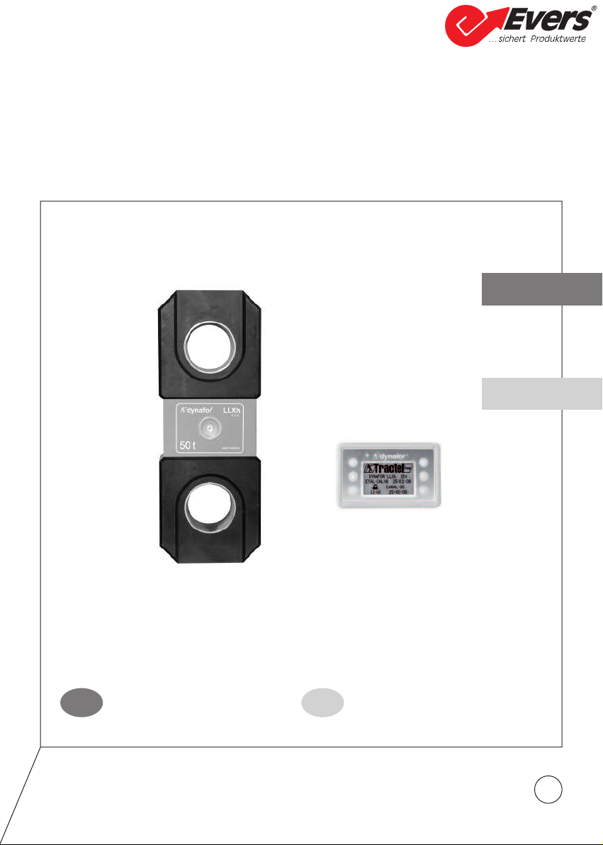
15/25/50/100/250t
Operation and maintenance
manual
Original manual
ebrauchs- und
Wartungsanleitung
Übersetzung der Originalanleitung
Français
English
Nederlands
Deutsch
B DE
dynafor™
1
Series LLXh Electronics Dynamometers
LLXh Elektronische Zugkraft-Messgeräte
Heben • Sichern • Fördern • Verpacken
Evers GmbH • Graf-Zeppelin-Straße 10-12 • 46149 Oberhausen • Telefon (02 08) 99 475-0 • Telefax (02 08) 99 475-31 • E-Mail [email protected] • www.eversgmbh.de

B
2
TABLE OF CONTENTS
page
PRIORITYRECOMMENDATIONS •••••••••••••••••••••••••••••••••••••4
DEFINITIONANDPICTO RAMS••••••••••••••••••••••••••••••••••••••5
1.PRESENTATION••••••••••••••••••••••••••••••••••••••••••••••••6
1.1.OperatingPrinciple ••••••••••••••••••••••••••••••••••••••6
1.2.Descriptionandmarking •••••••••••••••••••••••••••••••••••7
1.2.1.Sensor •••••••••••••••••••••••••••••••••••••••7
1.2.2.Displayunit ••••••••••••••••••••••••••••••••••••8
2.SPECIFICATIONS•••••••••••••••••••••••••••••••••••••••••••••••9
2.1.SensorandDisplayUnit •••••••••••••••••••••••••••••••••••9
2.2Anchoringaccessory •••••••••••••••••••••••••••••••••••••10
2.2.1Size •••••••••••••••••••••••••••••••••••••••••10
3. INSTALLATION, UTILIZATION AND UNINSTALLATION • • • • • • • • • • • • • • • • • 10,11
4.UTILIZATIONPROHIBITIONS ••••••••••••••••••••••••••••••••••••••11
5.OVERLOADINDICATOR •••••••••••••••••••••••••••••••••••••••••11
6. OPERATION IN SIN LE CONFI URATION • • • • • • • • • • • • • • • • • • • • • • • • • • • • 12
6.1. ommissioning •••••••••••••••••••••••••••••••••••••••••12
6.1.1. Enabling the sensor batteries • • • • • • • • • • • • • • • • • • • • • • • 12
6.1.2. harging the display unit • • • • • • • • • • • • • • • • • • • • • • • • • • 12
6.1.3. Turning on the sensor • • • • • • • • • • • • • • • • • • • • • • • • • • • • 12
6.1.4. Information provided by the sensor LED • • • • • • • • • • • • • • • • 12
6.1.5. Turning on the display unit • • • • • • • • • • • • • • • • • • • • • • • • • 13
6.2.Elementaryfunctions •••••••••••••••••••••••••••••••••••••13
6.2.1. Keypad function limitation • • • • • • • • • • • • • • • • • • • • • • • • • • 13
6.2.2.Detaileddescription ••••••••••••••••••••••••••••••14
6.2.3.Icons ••••••••••••••••••••••••••••••••••••••••14
6.2.4. Elementary functions and corresponding displays • • • • • • • • • 15
6.2.4.1. Standard display • • • • • • • • • • • • • • • • • • • • • • • • • 15
6.2.4.2. Navigating between icons • • • • • • • • • • • • • • • • • • 15
6.2.4.3. Measurement unit selection • • • • • • • • • • • • • • • • • 15
6.2.4.4.TareFunction •••••••••••••••••••••••••••15
6.2.4.5. MAX Function (Peak stress save) • • • • • • • • • • • • • 16
6.2.4.6. Language selection function • • • • • • • • • • • • • • • • • 17
6.2.4.7. Stopping the device • • • • • • • • • • • • • • • • • • • • • • 18
6.2.5.ErrorMessages•••••••••••••••••••••••••••••••••18
6.3.Advancedfunctions••••••••••••••••••••••••••••••••••••••18
6.3.1.MainMenu ••••••••••••••••••••••••••••••••••••18
The functions described hereinafter enable standard use of the dynafor™LLXh.
The possibilities offered by dynafor™LLXh extend well beyond these elementary functions, and
respond to the wide range of requirements encountered in industry.
To name but a few: display of several sensors on the same display unit, display of the stress
on one or more sensors on several display units, P link-up, saving, totalling, differentiation,
threshold management etc… all of these functions are described further on in this manual.
Heben • Sichern • Fördern • Verpacken
Evers GmbH • Graf-Zeppelin-Straße 10-12 • 46149 Oberhausen • Telefon (02 08) 99 475-0 • Telefax (02 08) 99 475-31 • E-Mail [email protected] • www.eversgmbh.de

B
3
6.3.1.1. Functions Menu • • • • • • • • • • • • • • • • • • • • • • • • • 18
6.3.1.1.1. Save • • • • • • • • • • • • • • • • • • 19
6.3.1.1.2. Total • • • • • • • • • • • • • • • • • • • 20
6.3.1.1.3. Safety threshold management • 21
6.3.1.2. Parameter setting menu • • • • • • • • • • • • • • • • • • • 22
6.3.1.2.1. Date and Time • • • • • • • • • • • • 22
6.3.1.2.2. oefficients • • • • • • • • • • • • • • 22
6.3.1.2.3.
Available memory check • • • • •
22
6.3.1.2.4.
Dynamic effect filtering • • • • • •
23
6.3.1.3.Languages•••••••••••••••••••••••••••••23
6.3.2. Other icons on the standard screen • • • • • • • • • • • • • • • • • • • 23
6.3.2.1. Sensor settings and data • • • • • • • • • • • • • • • • • • • 23
6.3.2.2. Display Unit Settings and Data • • • • • • • • • • • • • • • 23
6.3.2.3. Display unit and sensor identification and data • • • • 23
6.3.2.4. Data on the power and status of the radio link • • • • 24
7. OPERATION IN MULTIPLE CONFI URATION • • • • • • • • • • • • • • • • • • • • • • • • • • 24
7.1.Generalities •••••••••••••••••••••••••••••••••••••••••••24
7.2. Examples of multiple configurations • • • • • • • • • • • • • • • • • • • • • • • • • • 25
7.3.SafetyRecommendations •••••••••••••••••••••••••••••••••25
7.4. General procedure for setting up multiple configurations • • • • • • • • • • • • 26
7.5. Tools for setting up multiple configurations • • • • • • • • • • • • • • • • • • • • • • 27
7.5.1. Unlocking an assembly • • • • • • • • • • • • • • • • • • • • • • • • • • • 27
7.5.2.Lockinganassembly •••••••••••••••••••••••••••••27
7.5.3. Associating an assembly • • • • • • • • • • • • • • • • • • • • • • • • • • 28
7.5.4. Setting display unit parameters in Master and Slave mode • • • 28
7.5.5. Radio channel availability • • • • • • • • • • • • • • • • • • • • • • • • • 29
7.5.6. hanging the radio channel • • • • • • • • • • • • • • • • • • • • • • • • 29
7.5.7. Association of components • • • • • • • • • • • • • • • • • • • • • • • • • 30
7.5.7.1. Adding one or more sensors a) & b) • • • • • • • • • • • 30
7.5.7.2. Adding a Slave display unit a) & b) • • • • • • • • • 31, 32
7.6.
Display in multiple configuration
••••••••••••••••••••••••••••••33
7.6.1.
Multiple Display menu
•••••••••••••••••••••••••••••33
8.PCCONNECTION(OPTIONAL) ••••••••••••••••••••••••••••••••••••34
8.1.Description••••••••••••••••••••••••••••••••••••••••••••34
8.2. Messages with P connection • • • • • • • • • • • • • • • • • • • • • • • • • • • • • • 34
9. MAINTENANCE, CHECKIN AND CLEANIN • • • • • • • • • • • • • • • • • • • • • • • • • • 34
9.1. Battery and power pack status • • • • • • • • • • • • • • • • • • • • • • • • • • • • • • 34
9.2. hangingsensorbatteries •••••••••••••••••••••••••••••••••34
9.3.Regulatorycheck •••••••••••••••••••••••••••••••••••••••34
9.3.1. ertificate of Adjustment • • • • • • • • • • • • • • • • • • • • • • • • • • • 34
9.3.2. ISO 376 calibration certificate • • • • • • • • • • • • • • • • • • • • • • • 34
9.4.Maintenance•••••••••••••••••••••••••••••••••••••••••••34
10. STORA E, TRANSPORT, DISPOSAL • • • • • • • • • • • • • • • • • • • • • • • • • • • • • • • 35
11. OPERATIN ANOMALIES AND TROUBLESHOOTIN • • • • • • • • • • • • • • • • 35, 36
12.PRODUCTMARKIN ••••••••••••••••••••••••••••••••••••••••••36
Heben • Sichern • Fördern • Verpacken
Evers GmbH • Graf-Zeppelin-Straße 10-12 • 46149 Oberhausen • Telefon (02 08) 99 475-0 • Telefax (02 08) 99 475-31 • E-Mail [email protected] • www.eversgmbh.de
B
4
PRIORITY RECOMMENDATIONS
CAUTION. Possible situation. Hazardous. Risk of slight injury or damage of the appliance.
Appliance completely protected by double or reinforced insulation.
1. Before installing and using this unit, to ensure safe, efficient use of the unit, be sure you have read and fully
understood the information and instructions given in this manual. A copy of this manual should be made
available to every operator. Extra copies of this manual can be supplied on request.
2. Do not use the unit if any of the plates mounted on the unit are missing or if any of the information on the
plates, as indicated at the end of the manual, are no longer legible. Identical plates will be supplied on
request; these must be secured on the unit before it can be used again.
3. Make sure that all persons operating this unit know perfectly how to use it in a safe way, in observance of
all safety at work regulations. This manual must be made available to all users.
4. The positioning and commissioning of this appliance must be carried out under conditions that ensure
installer safety in compliance with the relevant regulations.
5. Each time, before using the unit, inspect the unit for any visible damage, as well as the accessories used
with the unit. Never use an appliance that is not obviously in good condition. Return the appliance to the
manufacturer for servicing if any anomalies arise that have no connection with the state of the battery.
6. Protect your appliance from any form of impact, especially the display unit.
7. The unit must never be used for any operations other than those described in this manual. The unit must
never be used to handle any loads exceeding the maximum utilization load indicated on the unit. It must
never be used in explosive atmospheres.
8. This appliance should never be used for man-riding applications without a thorough prior check that the
utilization coefficients required for personnel safety have been applied, and more generally that the safety
regulations for the load line on which it has been installed have been applied.
9. Tractel®declines any responsibility for use of this unit in a setup configuration not described in this manual.
10. Tractel®declines any responsibility for the consequences of any changes made to the unit or removal of
parts.
11. Tractel®declines any responsibility for the consequences resulting from disassembly of the unit in any way
not described in this manual or repairs performed without Tractel®authorization, especially as concerns
replacement of original parts by parts of another manufacturer.
12. As a Dynafor™ dynamometer is a lifting accessory, the safety regulations applicable to this category of
equipment must be applied.
13. If the unit is to be definitively removed from use, make sure the unit is discarded in a way which will prevent
any possible use of the unit. All environment protection regulations must be observed.
14. Any operation of this appliance in conjunction with supplementary equipment relaying signals on an
operating system must be preceded by a risk analysis related to the operating functions implemented,
carried out by the system user or assembler, and all appropriate measures are taken as a consequence.
15. ertified in compliance with European regulations, this appliance should be checked for compliance with
the regulations of any other country where it might be used, prior to being commissioned there.
16. The display power supply unit is used as a breaker and must be accessible at any time.
Heben • Sichern • Fördern • Verpacken
Evers GmbH • Graf-Zeppelin-Straße 10-12 • 46149 Oberhausen • Telefon (02 08) 99 475-0 • Telefax (02 08) 99 475-31 • E-Mail [email protected] • www.eversgmbh.de
B
5
DEFINITIONS AND PICTO RAMS
Definitions:
The following terms are used in this manual:
"Product": Equipment element or assembly defined on the cover page, delivered complete in
its standard version, or as one of the various models described.
"Installation": omprehensive set of operations required to place a complete product in a
condition ready for commissioning (or connection to other components for
commissioning), starting from the state in which the product has been delivered.
"User": Person or department in charge of management and safe use of the product
described in the manual.
"Technician": Qualified person in charge of the maintenance operations described and authorised
to the user by the manual; the technician is understood to be skilled and familiar with
the product.
"Operator": Person or department using the product in compliance with the purpose for which it
is intended.
"Sensor": LLX2 or LLXh sensor, or any other load cell implementing a strain gauge associated
to an LLXt module, thus becoming a component of an "LLX2 System".
"LLX2 System": Any force measuring system using LLX2 technology.
Pictograms used in this manual:
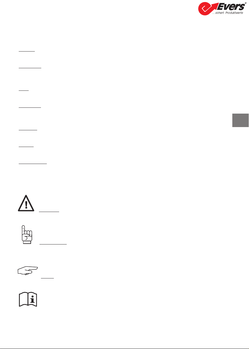
«DAN ER»: Remarks intended to prevent fatal, serious or minor injury to personnel or
damage to the environment.
«IMPORTANT»: Remarks intended to prevent a failure or damage to the product, but not
directly endangering the life or health of the operator or any other person, or
damage to the environment.
«NOTE»: Remarks concerning precautions to be taken to ensure easy, efficient installation,
use and maintenance.
You must read the user and maintenance manual.
Heben • Sichern • Fördern • Verpacken
Evers GmbH • Graf-Zeppelin-Straße 10-12 • 46149 Oberhausen • Telefon (02 08) 99 475-0 • Telefax (02 08) 99 475-31 • E-Mail [email protected] • www.eversgmbh.de

6
1 PRESENTATION
The dynafor™LLXh dynamometers are precision appliances (0.2% ISO 376 . 21° ), for measuring
pulling force and indicating loads. The capacity scale ranges from 150 kN to 2500 kN.
A dynafor™LLXh is made up of a sensor and a mobile display unit.
A two-way radio link-up using the 2.4 GHz wave band conects the two components.
16 radio channels are used. Each display unit and sensor have their own address, enabling unequivocal
identification in the event of a multiple set-up.
The shape of the dynamometers enable the use of standard shackles on both ends.
The technologies implemented on a radio and software level offer, aside from the standard uses to be
expected from an industrial dynamometer, multiple configuration possibilities that combine several
sensors with several display units. They also offer access to advanced function such as: saving,
threshold management, monitoring etc.
The P – USB link permits to dowload, save and manage measurements data. A display unit can be
configured as Master or Slave within a network.
The standard version of the equipment comes with batteries and power pack in a plastic carrying case for
capacities up to 50 t and wood case for 100 t and 250 t.:
a) A sensor
b) A display unit and battery charger
c) An operating and maintenance instruction manual
d) A certificate of adjustment
e) A certificate of E compliance
1.1 Operating Principle
The operating principle of the dynafor™LLXh is based on strain gauge measurement of the extension,
within its limits of elasticity, of a metal body subjected to traction stress.
The appliance will work in all directions.
The sensor generates an electrical signal that is proportional to the load. This signal is processed by a
micro-processor analyser and then transmitted via radio waves to the display unit, which immediately
displays the load applied to the sensor to which it is linked.
When switched on, the sensor data, such as identification and date of last metrology check, is displayed
on the display unit.
The display unit is compatible with all of the LLXh model sensors, irrespective of their capacity. Unless
otherwise ordered, the radio link-up between the LLXh and LLX2 sensor and the display unit is set
definitively in the factory before dispatch. After this, the radio link can be configured by the user to meet
their requirements.
B
Heben • Sichern • Fördern • Verpacken
Evers GmbH • Graf-Zeppelin-Straße 10-12 • 46149 Oberhausen • Telefon (02 08) 99 475-0 • Telefax (02 08) 99 475-31 • E-Mail [email protected] • www.eversgmbh.de
7
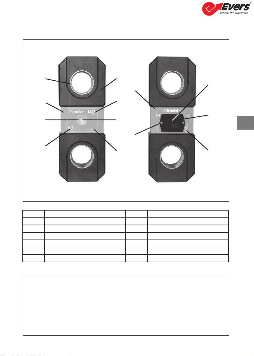
1.2 Description and marking
1.2.1 Sensor
Provisions applied:
-Machine Directives: 2006/42/ E
-CEM Directive: 2004/108/ E
-Electrical Safety: IE 61010-1 2nd Edition 2001
-Radio certifications: E : Radio Tests EN 300 440-2 V1.1.1 / USA & anada:
F ID / Australia: -Tick ID
- R&TTE Directive (1999/5/ E)
A
B
C
D
E
F
G
H
J
IK
L
M
Aentering ring HSerial N°.
BFront plate IRear plate
COperating indicator JFixing screw of L
DMaximum sensor capacity KBattery housing (3 x “AA”)
EBody LBattery cover
FDesignation and accuracy MManufacturerʼs label
On / Off button
B
Heben • Sichern • Fördern • Verpacken
Evers GmbH • Graf-Zeppelin-Straße 10-12 • 46149 Oberhausen • Telefon (02 08) 99 475-0 • Telefax (02 08) 99 475-31 • E-Mail [email protected] • www.eversgmbh.de

8
a
b
c
d
e
f
gh
i
o
j
k
l
m
n
o
aIndicator LED (manufacturer use) j
Attaching points for the display unit
on the bumper of the sensor
housing
bKey: "esc" kE Marking and Serial No.
c
Back light key
Press once = Auto OFF 90ʼʼ
Press three times = permanent >
OFF by pressing once
lharger socket
dKey: On / Off mSerial port (manufacturer use)
eKey: Enables available options and
clockwise browsing nUSB port
fKey: Enables available options and
anti-clockwise browsing oMetal wire
gKey: onfirm / Enter pharger 100-240 Vac 50/60 Hz. 180 mA
Secondary: 12 Vdc. 500 mA.
hSafety wrist strap qUniversal mounting kit
iL D graphic screen 128 x 64 pixels
67 x 40 mm
B
1.2.2 Display unit
Heben • Sichern • Fördern • Verpacken
Evers GmbH • Graf-Zeppelin-Straße 10-12 • 46149 Oberhausen • Telefon (02 08) 99 475-0 • Telefax (02 08) 99 475-31 • E-Mail [email protected] • www.eversgmbh.de
9
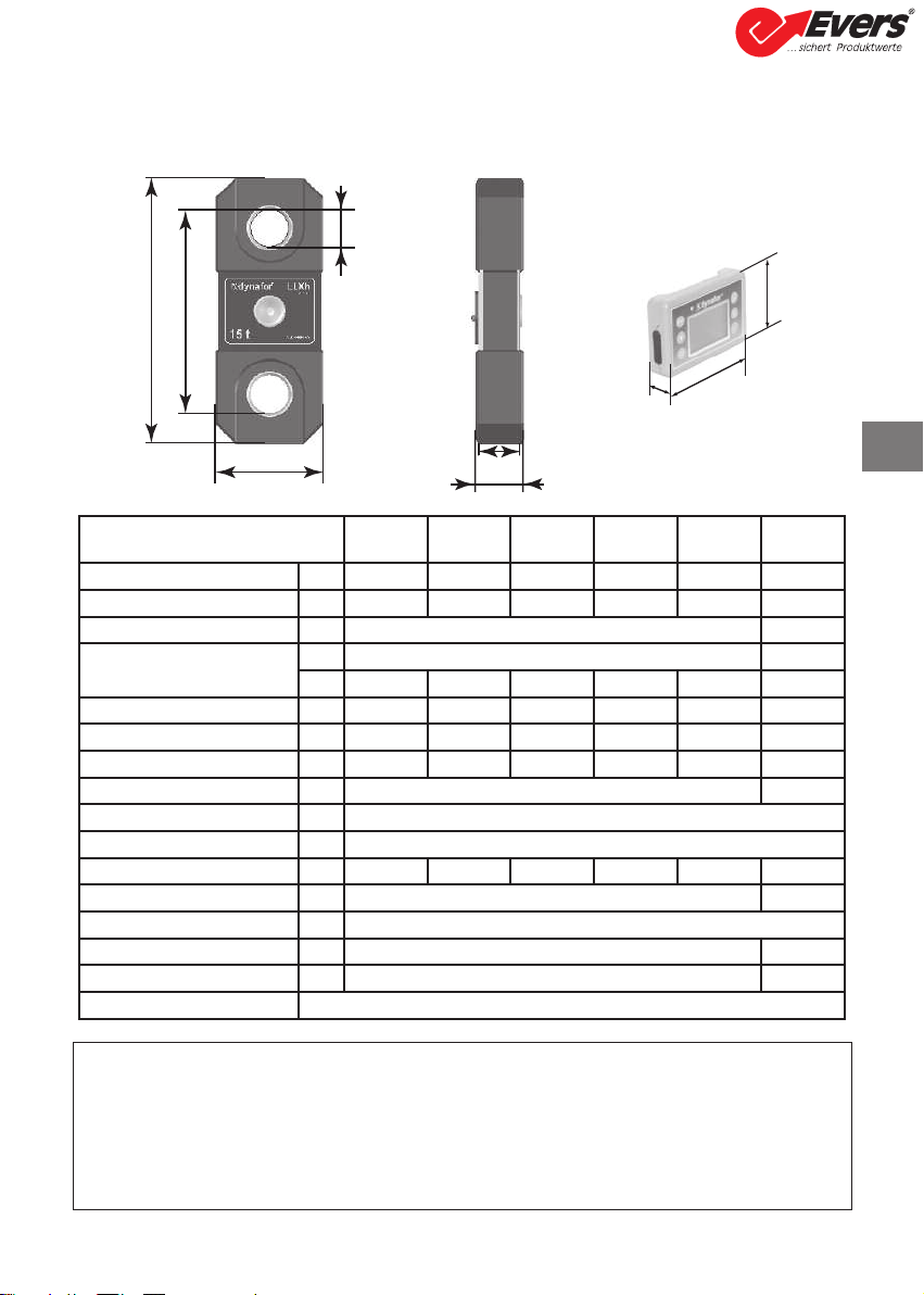
2. SPECIFICATIONS
2.1 Sensor and Display Unit
B
AB
C
DE
F
hi
j
MODEL LLXh
15 t
LLXh
25 t
LLXh
50 t
LLXh
100 t
LLXh
250 t Display
Maximum capacity t 15 25 50 100 250 ALL
Test load t 30 50 100 200 500 -
Safety coefficient Minimum 4 -
Precision 0,2 % selon ISO 376 . 21° -
daN 30 50 100 200 500 -
Increment daN 5 10 20 50 100 <-
Max. Display 16500 daN 27500 daN 55000 daN 110.00 t 275.00 t <-
Number height mm - - - - - 25
Autonomy From 300 to 1000 h depending of functions 48 h
Radio scope m 80 (in open field) (I.P. 67 = 60)
RF technology 2.4 Ghz
Weight kg 4 6.6 15.1 46 215 0.180
IP Protection I.P. 65 (I.P. 67 option) I.P. 54
Usafe
From - 20° to 40°
Sensitivity to T° 0.05% per 10°
Sensor material Aluminium -
Dimensions mm See technical data sheet 2027
For information, the radio range measured in laboratory is 80 m (60 m for IP 67) when the front
side of the sensor or of the LLXt module is pointing toward the back side of the display unit.
aution! This range may differ depending on circumstances, in particular:
- presence of obstacles.
- electromagnetic interference.
- under certain atmospheric conditions.
If you have any trouble or if you have a specific utilisation, contact the Tractel®network.
Heben • Sichern • Fördern • Verpacken
Evers GmbH • Graf-Zeppelin-Straße 10-12 • 46149 Oberhausen • Telefon (02 08) 99 475-0 • Telefax (02 08) 99 475-31 • E-Mail [email protected] • www.eversgmbh.de
10
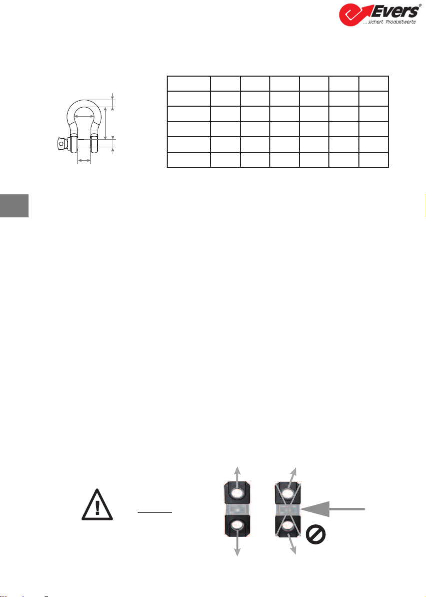
2.2 Anchoring accessory
Any shackle that complies with the relevant regulations can be used for dynafor™ LLXh to be mounted
onto a traction line, as long as it complies with the dynafor™ LLXh maximum capacity.
2.2.1 Size in mm
3 INSTALLATION, UTILIZATION AND UNINSTALLATION
3.1 Conditions prior to set-up and use
- Altitude: Up to 2000 m
- Relative humidity: Max 80%
- Degree of pollution assigned: 2
Before setting up and using the dynamometer you must:
a) make sure that there is no stress value shown when the appliance is not subject to traction.
Should this occur, refer to hapter 11 Operating Anomalies and Troubleshooting.
b) make sure that the sensor batteries and display unit power pack are adequately charged.
c) make sure that there is a good radio link between the sensor and the display unit.
d) use the "ID" icon to check that the sensor serial number shown on the sensor plate is the
same as the sensor serial number shown by the display unit (see section 6.2.2 and section
6.2.3).
3.2 Installation
When installing you must:
a) make sure that the load line anchoring point(s) are sufficiently robust in relation to the
traction that will be applied.
b) make sure that the anchoring accessories at either end of the dynamometer are compatible,
and that they comply with the relevant regulations.
c) make sure that clevis pins are well locked, with the nut screwed down to the maximum, and
make sure that the hook safety latch is working correctly.
d) make sure that the sensor is correctly aligned in the traction line.
E
A
D
C
B
WLL A B D E kg
15 t 98 41 146 41 60 7.8
25 t 110 44 178 50 73 14
50 t 150 64 267 70 105 39.7
100 t 241 89 381 95 146 97
250 t 320 125 540 140 200 340
B
OK
«DAN ER»
Heben • Sichern • Fördern • Verpacken
Evers GmbH • Graf-Zeppelin-Straße 10-12 • 46149 Oberhausen • Telefon (02 08) 99 475-0 • Telefax (02 08) 99 475-31 • E-Mail [email protected] • www.eversgmbh.de

11
3.3 Utilization
Only use dynafor™ LLXh in traction, avoiding compression, twisting or flexing.
The appliance can be used in all directions, including horizontally.
The dynafor™ LLXh operates correctly in a temperature range of de –20° to + 40° . For use outside
of this range, the appliance will require heat protection.
3.4 Uninstallation
When uninstalling the appliance, first make sure that it is no longer subject to any traction stress.
4 UTILIZATION PROHIBITIONS
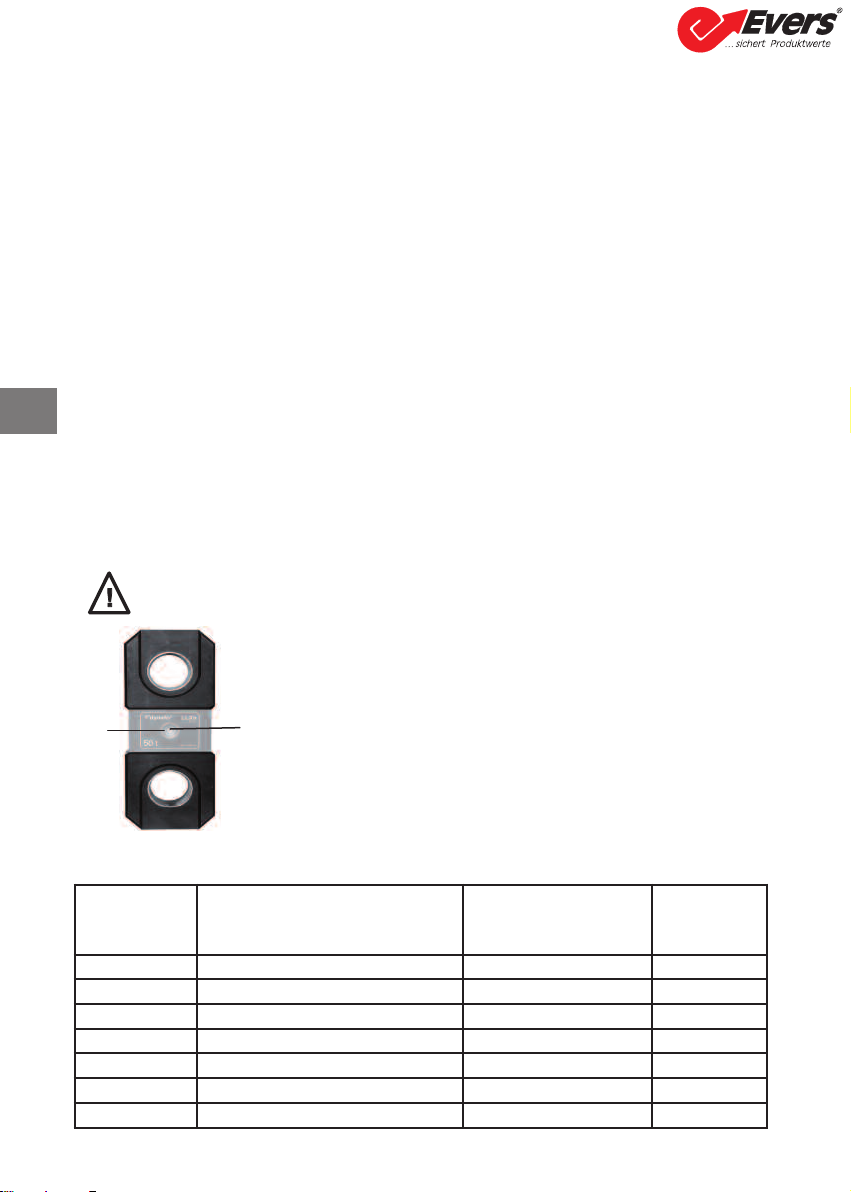
5 OVERLOAD INDICATOR «DAN ER»
It is prohibited:
• To use dynafor™ LLXh in a line for lifting people without having carried out a prior
specific risk analysis.
• To modify the appliance housing by machining, drilling or any other process.
• To use dynafor™ beyond their maximum capacity.
• To put the Dynafor™ in a arc weld electrical circuit.
• To disassemble or uncover the sensor or display unit.
• To use the appliance for operations other than those described in this manual.
In the event of overload, all stress on the sensor must be completely relieved and a check
made that the appliance returns to zero.
If the appliance shows a stress value, even though tension is not applied, then it has suffered
a permanent distortion. In this case, you must have the appliance serviced by the manufacturer
before continuing to use it.
When the load applied to the sensor exceeds the maximum
capacity of the appliance of 10 % (e.g.: a 25 t loaded at 27.5 t) the
display unit indicates an overload message "HI" as shown
opposite, and emits an intermittent beep.
If several sensors are connected to the display unit, the overloaded
sensor will be immediately identified.
In the example display opposite, relating to a two-sensor set up,
the sensor on the second line is overloaded.
B
Heben • Sichern • Fördern • Verpacken
Evers GmbH • Graf-Zeppelin-Straße 10-12 • 46149 Oberhausen • Telefon (02 08) 99 475-0 • Telefax (02 08) 99 475-31 • E-Mail [email protected] • www.eversgmbh.de
12
6 OPERATION IN SIN LE CONFI URATION
Single configuration consists of using an assembly made up of one sensor and one display unit for
measuring and displaying the stress on the sensor. Depending on the userʼs requirements, the display
unit can either be attached to the sensor or be separated from it.
Unless otherwise ordered, the radio link-up between the sensor and the display unit is set definitively
in the factory before dispatch. After this, the radio link can be configured by the user to meet their
requirements (see hapter 7: Operation in multiple configuration).
6.1 Commissioning
6.1.1 Enabling the sensor batteries
The 3 x 1.5 V "AA" batteries are installed in the factory.
Remove the insulating tab protruding from the battery compartment to enable them.
For future battery changes, refer to hapter 9.2.
6.1.2 harging the display unit
The display unit is delivered with the power pack charged.
Afterwards, use the charger provided to charge the power pack.
harging time: 3 h.
The display unit can be used during charging.
6.1.3 Turning on the sensor
6.1.4 Information provided by the sensor LED
DAN ER: Always turn on the sensor before turning on the display unit; otherwise the
display unit will not be able to establish the radio link.
The ON/OFF switch is actuated by pressing lightly at the centre of
the membrane.
On power up, the two red LEDs flash.
To switch off, press and hold the switch lightly for 3 seconds.
Sensor
operating
MODE
Sensor LED
flashing
Measures
per second Autonomy
Stop Off - -
Standard 1 flash per second 4 per second 300 h
Standard slow 1 flash every 2 seconds 1 per second 500 h
Power saving 1 flash every 4 seconds 1 every 4 seconds 1000 h
Standby 1 flash every 8 seconds - 3000 h
Peak load 2 flashes per second 32 per second 100 h
Batteries low Same but one LED at a time -
ON
OFF
LED
B
Heben • Sichern • Fördern • Verpacken
Evers GmbH • Graf-Zeppelin-Straße 10-12 • 46149 Oberhausen • Telefon (02 08) 99 475-0 • Telefax (02 08) 99 475-31 • E-Mail [email protected] • www.eversgmbh.de

6.1.5 Turning on the display unit
The welcome screen is shown for 4 seconds, then the standard display window is shown.
6.2 Elementary functions
This chapter presents the functions that enable elementary use of dynafor™LLXh.
6.2.1 Keypad function limitation
This function is used to limit access to the advanced functions of the display unit.
In «Limited» mode, only the three basic functions are accessible: UNITS, TARE, MAX.
In «Full access» mode, all the functions are accessible.
Transition from one mode to another is achieved by a sequence of buttons on the front panel of the
display unit.
This function facilitates use of the LLX2 System by the operator while eliminating the risk of an
inadequate operation due to certain parameters being changed.
6.2.1.1 Deactivate «Limited» mode:
Press the ES key when the display unit is switched off.
The next time the display unit is powered up, the MENU icon will appear in the upper left corner of the
screen in place of the icon representing a key.
6.2.1.2 Activate «Limited» mode:
Press the ES key when the display unit is switched off.
The next time the display unit is powered up, an icon representing a key will appear in the upper left
corner of the screen in place of the MENU icon.
LIMITED mode FULL A ESS mode
13
Sensor
Identification
Date of last
metrological
check
Metrological
check
Link locked
ON / OFF (3 sec) urrent time urrent date
Radio
channel used
A
B
Heben • Sichern • Fördern • Verpacken
Evers GmbH • Graf-Zeppelin-Straße 10-12 • 46149 Oberhausen • Telefon (02 08) 99 475-0 • Telefax (02 08) 99 475-31 • E-Mail [email protected] • www.eversgmbh.de

B
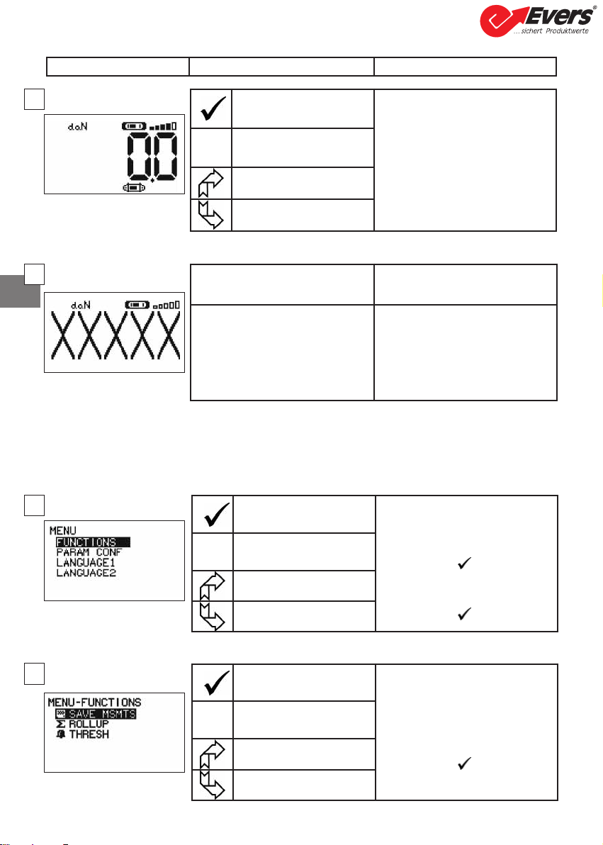
6.2.1.3 Standard screen in "Limited" mode
In this manual, this number refers to the position of the screen in the block diagram at the end of the manual.
6.2.2 Detailed description
In «full access» mode, display all the icons by pressing one of the or buttons.
6.2.3 Icons
a) Active icons:
Menu access icon: offers access to advanced functions (See chapter 6.3).
Units access icon: enables measurement unit selection (See section 6.2.4.3).
Tare Function access icon: enables Tare function (Gross / Net Load) (See section 6.2.4.4).
Peak Stress access icon: enables the maximum stress save function (See section 6.2.4.5).
Display unit data access icon: shows display unit power pack charge and data relating to the display
unit (See section 6.3.2.2).
Transmission data access icon: enables viewing and modification of the radio network status (see
section 6.3.2.4).
Identification access icon: enables viewing of network equipment identification (see section 6.3.2.3).
Sensor data access icon: Shows sensor battery charge and data relating to the sensor (See section
6.3.2.1).
b) Indicator Icons:
Alarm Indicators: appear if one or more safety thresholds have been set, flashing if exceeded.
Printer indicators: not used in this version.
Filter indicator: appears if one of the dynamic effect filters is activated. This indicator takes priority
over the printer icon.
Menu access
icon
Unit access
icon
Filter and Alarm
indicators
Battery level and display
unit data access icon Network
transmission data
access icon
Positive or
negative value
stress indicator
Stress
value
Tare Function
access icon
Peak stress
access icon
Battery level and
Sensor data
access icon
Identification
access icon
Action omments
No action Standard display in "Limited" mode:
Following the welcome screen, the
standard screen automatically appears.
The sensor/display unit assembly is
ready for use in "Limited" mode.
Only the Units, Tare and Max functions
are accessible (See § 6.2.4.3/4/5).
ESC No action
Navigate between
functions. Units, Tare
and Max.
Navigate between
functions. Units, Tare
and Max.
X
14
Heben • Sichern • Fördern • Verpacken
Evers GmbH • Graf-Zeppelin-Straße 10-12 • 46149 Oberhausen • Telefon (02 08) 99 475-0 • Telefax (02 08) 99 475-31 • E-Mail [email protected] • www.eversgmbh.de

15
6.2.4 Elementary functions and corresponding displays
6.2.4.1 Standard display
6.2.4.2 Navigating between icons
6.2.4.3 Measurement unit selection
6.2.4.4 Tare Function
Display Action omments
No action Standard Display:
Sensor stress.
Measurement units.
Dynamic effect filtering, see
advanced functions § 6.3.1.2.4.
Display unit power pack level.
Sensor battery level.
Radio reception level.
ESC No action
Select an icon
Select an icon
onfirm current selection Navigation:
By pressing on either of the two
arrows, all available functions
are displayed.
Move from icon to icon using
the arrows.
ESC Return to standard display
Move clockwise from icon to
icon
Move anti-clockwise from icon
to icon
onfirm selection
Select Unit: daN, kN, kg, t,
Lbs, Ton.
Select the unit icon, which starts
flashing.
onfirm with
Enable the various unit symbols:
onfirm with
For 100 t and 250 t use : kN, t,
Ton
ESC Return to standard display
without modification
Select an icon and enable the
available options
Select an icon and enable the
available options
onfirm TARE option when it
is highlighted.
TARE Function:
Select the TARE icon, which
starts flashing.
onfirm with
Enable the various options.
onfirm with
TARE = Initialise a new Tare
RAW = Sum of NET + TARE
NET = Difference between RAW - TARE
ESC Return to standard display
without modification
Select an icon and enable the
available options
Select an icon and enable the
available options
1
2
3
4
B
Heben • Sichern • Fördern • Verpacken
Evers GmbH • Graf-Zeppelin-Straße 10-12 • 46149 Oberhausen • Telefon (02 08) 99 475-0 • Telefax (02 08) 99 475-31 • E-Mail [email protected] • www.eversgmbh.de

16
6.2.4.5 MAX Function (Peak stress save)
Reset MAX value to current
stress level
Peak load function:
From the Standard screen, go to
the MAX icon.
onfirm with
The "in progress" screen appears
while the display unit dialogues
with the sensor to change to
"Peak Load" mode - 32 measures
per second.
ESC Return to standard display
No action
No action
Reset MAX value to current
stress level Peak load function:
The peak load value is displayed.
The barograph represents 100%
of sensor capacity.
The cursor indicates the peak
value of stress.
The moving black line shows the
immediate stress value.
ESC Return to standard display
Enable MAX window selection
mode
Enable MAX window selection
mode
Display Action omments
onfirm selection
Advanced Peak load functions:
In this mode you can saves the
peak stress set saves.
Using the arrows and from the
MAX window, select the icon:
Diskette and confirm with to
save.
The printer icon is not used in this
version.
ESC Return to MAX display
Move clockwise from icon to
icon
Move anti-clockwise from icon
to icon
5
6
7
B
Heben • Sichern • Fördern • Verpacken
Evers GmbH • Graf-Zeppelin-Straße 10-12 • 46149 Oberhausen • Telefon (02 08) 99 475-0 • Telefax (02 08) 99 475-31 • E-Mail [email protected] • www.eversgmbh.de
17
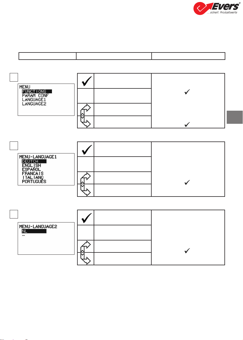
6.2.4.6 Language selection function
onfirm selection Language group selection:
Select the MENU icon.
onfirm with
Select the
required language group:
LANGUAGE 1,
LANGUAGE 2.
onfirm with
ESC Return to standard display
without modification
Select the available options
Select the available options
onfirm selection
Language selection:
Select the required language.
onfirm with
ESC Return to previous display
without modification
Select the available options
Select the available options
onfirm selection
Language selection:
Select the required language.
onfirm with
ESC Return to previous display
without modification
Select the available options
Select the available options
Display Action omments
8
9
10
B
Heben • Sichern • Fördern • Verpacken
Evers GmbH • Graf-Zeppelin-Straße 10-12 • 46149 Oberhausen • Telefon (02 08) 99 475-0 • Telefax (02 08) 99 475-31 • E-Mail [email protected] • www.eversgmbh.de
B
18
6.2.4.7 Stopping the device
6.2.5 Error Messages
No radio reception
6.3 Advanced functions
This chapter presents the functions that enable advanced use of dynafor™ LLXh.
See the general overview of the programme at the end of the manual.
6.3.1 MAIN Menu
6.3.1.1 Functions Menu
onfirm selection Main Menu:
Select MENU.
onfirm with
Select the required sub-menu.
onfirm with
ES Return to standard display
without modification
Select an icon and enable the
available options
Select an icon and enable the
available options
Possible causes Solutions
Sensor switched off or switched to
the standby mode.
Sensor too far from display unit.
Network conflict.
High electrical magnetic interference.
Switch off display unit, switch on
sensor, switch on display unit.
Bring appliances closer together.
heck network configuration
(see advanced functions section
6.3.2.4).
Display Action omments
No action
Stopping the device:
Keep the ON / OFF button
depressed for 3 seconds to switch
off the display unit.
The sensor automatically moves into
standby mode, and will start up
again when the display unit is
switched on.
If necessary you can switch off the
sensor by pressing on the ON / OFF
button.
ES No action
Select an icon and enable the
available options
Select an icon and enable the
available options
onfirm selection
Functions Menu:
Select the required sub-menu.
onfirm with
ES Return to standard display
without modification
Select an icon and enable the
available options
Select an icon and enable the
available options
11
12
13
14
Heben • Sichern • Fördern • Verpacken
Evers GmbH • Graf-Zeppelin-Straße 10-12 • 46149 Oberhausen • Telefon (02 08) 99 475-0 • Telefax (02 08) 99 475-31 • E-Mail [email protected] • www.eversgmbh.de

19
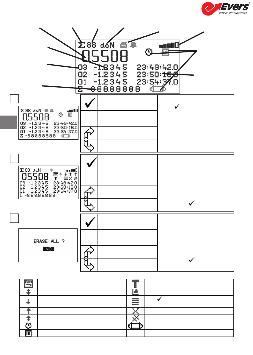
6.3.1.1.1 Save
Save sub-menu keys
Save Storing measurements:
Press to save:
The operation No.
The load value displayed.
The time of save
or date of save
or No. of corresponding sensor.
If several sensors are shown, the
total is taken into consideration.
ES Return to standard display
Select an icon and enable the
available options
Select an icon and enable the
available options
onfirm selection Save sub-menu:
Select the sub-menu.
See details and keys inthe
following table.
onfirm with
ES Return to previous display
Select an icon and enable the
available options
Select an icon and enable the
available options
onfirm selection Confirmation screen:
In the event of total deletion,
confirmation is required.
Select one of the options
onfirm with
ES Return to previous display
Select an icon and enable the
available options
Select an icon and enable the
available options
urrent
measurement
value
Entry number
Stress value at
time of entry
Save Logo Save number Measurement P transfer and alarm
indicators
Radio reception
level
Information at time
of save:
Time, date or ID
Type of data
Time, date or ID
17
16
15
Not used in this version hoose between G "gros" or N "net" of the
displayed value
Scroll page by page downwards Graphic (disabled function)
Scroll line by line downwards Press to display one after another: The time, the
date or sensor identification
Scroll line by line upwards Delete selected line
Scroll page by page upwards Delete all (followed by confirmation screen)
Displays the time Displays sensor identification
Displays the date
B
Heben • Sichern • Fördern • Verpacken
Evers GmbH • Graf-Zeppelin-Straße 10-12 • 46149 Oberhausen • Telefon (02 08) 99 475-0 • Telefax (02 08) 99 475-31 • E-Mail [email protected] • www.eversgmbh.de
20
6.3.1.1.2 Total
Total sub-menu keys
Save and total Total measurements:
Press to save and total:
The operation No.
The stress value displayed
The time of operation
or date of operation
or No. of corresponding sensor.
If several sensors are shown, the
total is taken into consideration.
ES Return to standard display
Select an icon and enable the
available options
Select an icon and enable the
available options
onfirm selection Total sub-menu:
Select the sub-menu.
See details and keys in the
following table.
onfirm with
ES Return to previous display
Select an icon and enable the
available options
Select an icon and enable the
available options
onfirm selection Confirmation screen:
In the event of total deletion,
confirmation is required.
Select one of the options
onfirm with
ES Return to previous display
Select an icon and enable the
available options
Select an icon and enable the
available options
Measure in
progress
Total Logo No. of totals Measurement
units
Transmission to P
and alarm indicators
Radio
reception
level
Stress value at
time of entry
Entry number
Accumumated
total of all
entries
Type of data:
Time, date or ID
Data at time of save:
Time, date or ID
18
19
20
Not used in this version hoose between G "gros" or N "net" of the
displayed value
Scroll page by page downwards Graphic (disabled function)
Scroll line by line downwards Press to display one after another: The time, the
date or sensor identification
Scroll line by line upwards Delete selected line
Scroll page by page upwards Delete all (followed by confirmation screen)
Displays the time Displays sensor identification
Displays the date
B
Heben • Sichern • Fördern • Verpacken
Evers GmbH • Graf-Zeppelin-Straße 10-12 • 46149 Oberhausen • Telefon (02 08) 99 475-0 • Telefax (02 08) 99 475-31 • E-Mail [email protected] • www.eversgmbh.de
This manual suits for next models
16
Table of contents
Languages:
Other Evers Measuring Instrument manuals

Popular Measuring Instrument manuals by other brands

Show Tec
Show Tec Shogun 3D+RGB user manual

In-situ
In-situ ChemScan mini UV254 Installation, operation and maintenance manual

Hellermann Tyton
Hellermann Tyton T609 instruction manual

Air TEc
Air TEc 89NAH manual

Scantronic
Scantronic Multiscan Nursecall Manager manual

HANYOUNG NUX
HANYOUNG NUX GR200 Series user manual


