EVERSPRING SA801 User manual

SA801
User manual - Manuale utente - Guía de usuario

1
Wall mounting plate
SA801 WIRELESS KEYPAD
Installation Instructions
General Introduction
The Wireless Keypad is used to Arm/Disarm the system by using a four digit
access code authentication. Users may assign different PIN codes to identify
and allow control by members of the family. The Keypad also incorporates a
Panic function for emergency use and an anti-tamper protection feature that will
immediately initiate a Full Alarm condition when anyone attempts to open its
casing. Its great compatibility with our U-Net family security products makes it
suitable for smart home cloud based platforms such as HomeSys.
Product Layout
Key Meaning of Key
0 - 9 Access code input
Arm
Part-arm 1
Part-arm 2
Disarm
Binding with HomeSys
1. Loosen and remove the locking screw
from the bottom of the Keypad.
2. Remove the wall mounting plate.
3. Prepare three AA 1.5V alkaline batteries. Do not insert them into the unit yet.
4. Log into the Homesys account from a web browser.
5. Select “System”, then “Add a Device”.
6. Select “Keypad”.
Setting/low battery LED

2
7. The following screen will appear. This means the gateway is entering binding
mode.
8. Insert the batteries with correct polarity at this point.
9. The screen below will appear in 10 seconds if the process is successful.
10. Time-out will occur if the binding process was unsuccessful. Please refer to
the Manual Binding procedure below.
Manual Binding
1. Repeat steps 5 to 8 of the Binding with HomeSys section.
2. Press buttons 1-2-3-4-3, the keypad should enter binding mode.
3. This screen below will appear in 10 seconds if the process is successful.
Configuration
Set Users and their access codes:
1. From your HomeSys account select “SETTINGS”, then “System”.

3
2. In “Keypad codes”, enter the Username in the first box, and the desired
access code in the second box (it will appear starred).
3. Click on “+” to enter multiple users and code (code 1, code 2, etc).
Note:
- Please use a different password for each user.
- All access codes are not stored in the keypad, instead they are stored in the
gateway and in the cloud platform. This way you can add as many keypads
without having to set up each one.
Operation
1. Setting Security Modes
a. First press either the Arm key , Part-arm1 key ,
Part-arm2 key or the Disarm key on the keypad.
b. Then enter one of the 4-digit access codes created during the
configuration.
c. If code entry is correct, the backlight of digits 0~9 on the Keypad will
extinguish. The back light of digits 0~9 will flash three times if
unsuccessful.
Note: See “Keypad self lockout” about unauthorized entry detection.
2. Panic
Press + simultaneously for 2 seconds.
The keypad will emit the radio signal to the system and a full alarm condition will
occur.
3.Keypad self lock
a. When an incorrect code is entered once, the back light of digits 0~9 will
start to flash 3 times.
b. If incorrect codes are entered three times consecutively, the keypad will be
locked out for the next 30 seconds. During this period the keypad will not
respond to any keypad press.
c. Following subsequent lockout of three times, the keypad will alert the
gateway of an unauthorized entry attempt.
4.Tamper Protection
The Keypad incorporates a tamper protection feature to protect against
unauthorized attempts to disassemble it. Any attempt to remove the keypad
from its wall plate will trigger the tamper switch which then initiates an alarm
condition.
Mounting the Keypad
The Keypad should be mounted in a position close to the main entrance door so
that the access codes can be entered easily.
Ensure that the position selected for the Keypad is within the effective range of
the HomeSys gateway.
Note: Do NOT fix the Keypad to metalwork or locate the unit within 1 meter of
metalwork (i.e. radiators, water pipes, etc) as this could affect its radio range.
Tamper
Switch

4
1. Undo and remove the fixing screw from the bottom edge of the Keypad and
remove the wall mounting plate (Figure 2).
2. Using the mounting plate as a template, mark the positions of the two fixing
holes on the wall.
3. Fix the mounting plate to the wall using the screws and wall plugs provided
(Figure 3). Do not over-tighten the fixing screws as this may distort or
damage the mounting plate.
4. With batteries installed inside, slide the keypad into its wall mounting plate
and screw the fixing screw to secure it in place. Do not over-tighten the
screw.
Enabling/Disabling the Panic function
If the keypad is mounted outside of your home, e.g. in apartment hallway or
stairs, you may choose to disable the Panic function to prevent abuse by
strangers triggering an alarm condition in your home.
To do this you need to enter the keypad’s own administrator PIN code. This is
separate from the access code created under “Configuration” section.
Note: The default administrator PIN code is 1-2-3-4. It is recommended that
you change this to another four digit number. See the next section on how to do
this.
a. Panic Disable:
Press administrator PIN code followed by “0”, e.g. 1-2-3-4-0
b. Panic Enable:
Press administrator PIN code followed by “1”, e.g. 1-2-3-4-1
Note: the default setting is enabled.
Changing the Administrator PIN code
To change the Administrator password, press the following keys in sequence:
1. Press current administrator code followed by “2”, e.g. 1-2-3-4-2
2. Enter new administrator code followed by “2”, e.g. 8-8-8-8-2
If you have forgotten the administrator PIN code, refer to section “Reset to
factory” to reset the PIN code.
Maintenance
If the battery level becomes low, the low battery LED will flash 4 times when any
key is pressed. Batteries should be replaced as soon as possible by following
the steps below:
Note: Removing the keypad from its wall mount will trigger the tamper
protection switch and cause an alarm. Prepare a keyfob controller SR804 ready
to quickly disarm the system or use the App.
1. Undo the fixing screw at bottom of keypad and remove it from the wall
mounting plate.
2. Replace with three AA alkaline batteries.
3. Refit and secure the Keypad onto the mounting plate.

5
Troubleshooting
The troubleshooting table lists some possible causes and solutions. Please
contact your original retailer or nearest service center if the below solutions
cannot solve your problem.
Symptom Possible Cause Recommendation
SA801 LED indicator not
displaying No battery is inserted or
battery is flat Check if 3 batteries are
inserted properly
SA801 failure Send the unit to the service
center and do not open it
The LEDs on the keypad
are operating properly, but
the keypad cannot arm or
disarm the system.
Check if the keypad has
completed binding with
Gateway .
Proceed with “Manual
binding”
Distance out of
operating range Change the mounting
location of SA801 closer to
the gateway.
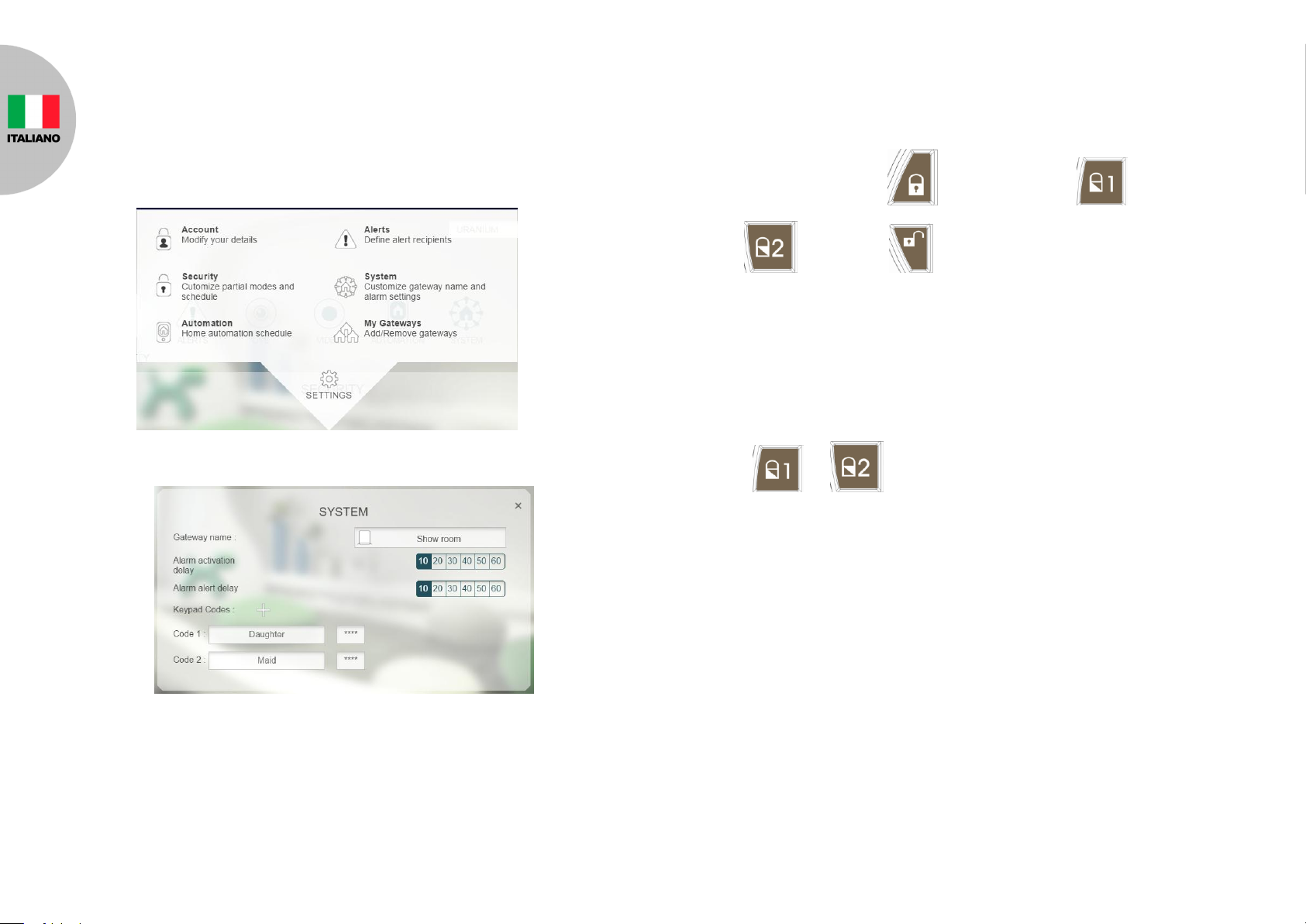
Reset to factory default
Resetting the keypad to factory default settings will remove all binding with
HomeSys and resets the administrator PIN code to factory default.
To reset to factory default:
1. Remove the batteries.
2. Set the Jumper link J1 to Off position as shown below:
3. Refit the batteries. The Keypad numbers 0-9 will flash three times.
4. Set the Jumper link J1 back to the ON position as shown above.
Specifications
** Specifications are subject to change and improvement without notice.
Federal Communication Commission Interference Statement
This equipment has been tested and found to comply with the limits for a Class
B digital device, pursuant to Part 15 of the FCC Rules. These limits are
designed to provide reasonable protection against harmful interference in a
residential installation. This equipment generates, uses and can radiate radio
frequency energy and, if not installed and used in accordance with the
instructions, may cause harmful interference to radio communications.
However, there is no guarantee that interference will not occur in a particular
installation. If this equipment does cause harmful interference to radio or
television reception, which can be determined by turning the equipment off and
on, the user is encouraged to try to correct the interference by one of the
following measures:
- Reorient or relocate the receiving antenna.
- Increase the separation between the equipment and receiver.
- Connect the equipment into an outlet on a circuit different from that to
which the receiver is connected.
- Consult the dealer or an experienced radio/TV technician for help.
This device complies with Part 15 of the FCC Rules. Operation is subject to the
following two conditions: (1) This device may not cause harmful interference,
Battery Type
AA 1.5V Alkaline battery x 3
Operating Frequency
868MHz (EU)/ 923MHz (America)
OFF position
ON position
A501112398R01

6
and (2) this device must accept any interference received, including interference
that may cause undesired operation.
FCC Caution: Any changes or modifications not expressly approved by the
party responsible for compliance could void the user's authority to operate this
equipment.
This transmitter must not be co-located or operating in conjunction with any
other antenna or transmitter.
WARNING:
Do not dispose of electrical appliances as unsorted municipal waste, use
separate collection facilities.
Contact your local government for information regarding the collection systems
available.
If electrical appliances are disposed of in landfills or dumps, hazardous
substances can leak into the groundwater and get into the food chain, damaging
your health and well-being.
When replacing old appliances with new ones, the retailer is legally obligated to
take back your old appliance for disposal at least for free of charge.
www.everspring.com
3F., No. 50, Sec 1, Zhonghua Rd., Tucheng Dist.,
New Taipei City 23666, R.O.C

1
Wall mounting plate
SA801 TASTIERA WIRELESS
Guida all’installazione
Introduzione
La tastiera wireless è usata per Armare/Disarmare il sistema con un codice di
accesso a 4 cifre. E’ possibile creare un codice diverso per ogni membro della
famiglia. Il dispositivo dispone inoltre di una combinazione antipanico e anti
manomissione in caso di emergenze o di tentata manomissione. La tastiera
SA801 funziona nel sistema smart home basato su cloud Homesys.
Descrizione
Tasto Significato
0 - 9 Codice d’accesso
Armare
Arm parz 1
Arm parz 2
Disarmare
Aggiungere ad Homesys
1. Svitare e rimuovere la vite posta sul lato inferiore del dispositivo.
2. Rimuovere la placca posteriore della tastiera.
3. Preparare 3 batterie tipo AA 1.5V alkaline. Per il momento non inserire le
batterie.
4. Accedere al proprio sistema Homesys da pagina web.
5. Selezionare “Sistema” quindi “Aggiungi dispositivo”.
Indicatore LED

2
6. Selezionare “Tastiera”.
7. Appare la seguente schermata. Significa che la centrale IPBOX ha iniziato
la ricerca di dispositivi.
8. Inserire le batterie con la polarità corretta.
9. Se il processo ha successo, entro 10 secondi appare la seguente
schermata.
10. Se la ricerca non dá esito, dopo 3 min il conteggio scade. Leggere “Ricerca
manuale”per aggiungere il dispositivo.
Ricerca manuale
1. Ripetere i passi da 5 a 8 di “Aggiungere ad Homesys”.
2. Premere i tasti 1-2-3-4-3 della tastiera per attivare il modo ricerca.
3. Se il processo ha successo, entro 10 secondi appare la seguente
schermata.

3
Configurazione
Creare nuovi utenti e codici di accesso:
1. Dal proprio account Homesys selezionare “IMPOSTAZIONI”, e “Sistema”.
2. In “Keypad codes”, enter the Username in the first box, and the desired
access code in the second box (it will appear starred).
3. Cliccare “+” per inserire piu utenti e codici (codice 1, codice 2, ecc).
Note:
- Usare un codice diverso per ogni utente.
- I codici di accesso non sono memorizzati nella tastiera ma nella centrale e
nell’account cloud. In tal modo si possono installare piu tastiere senza
bisogno di configurarle una alla volta.
Utilizzo
1. Cambiare stato di protezione sistema
a. Premere il tasto armare , armare parz 1 , armare parz
2 o Disarmare della tastiera.
b. Inserire uno dei codici a 4 cifre configurato in precedenza.
c. Se il codice è corretto la luce dei tasti 0~9 sulla tastiera si spegne. Se
invece i tasti lampeggiano 3 volte significa che il codice è errato.
Note: Vedi “Blocco automatico tastiera” per info su accesso protetto.
2. Antipanico
Premere + contemporaneamente per 2 secondi.
La tastiera invia alla centrale un segnale di attivazione instantanea dell’allarme.
3.Blocco automatico tastiera
a. Se si inserisce una volta un codice errato dalla tastiera, I tasti 0~9 della
tastiera lampeggiano 3 volte.
b. Se si inserisce un codice errato consecutivamente per 3 volte, la tastiera si
blocca per 30 secondi. Durante questo periodo i tasti della tastiera
vengono disabilitati.
c. Dopo 3 tentativi senza successo, la tastiera notifica la centrale di un
tentativo di accesso non autorizzato.

4
1. Svitare e rimuovere la vite sul lato inferior del dispositivo e rimuovere la
placca posteriore.
2. Usare la placca posteriore come riferimento per segnare i punti dove
inserire le viti nella parete.
3. Fissare la placca posteriore alla parete utilizzando le viti e i tasselli forniti
nella confezione. Non avvitare troppo stretta la placca per evitare di piegarla
o danneggiarla.
4. Inserire la tastiera con le pile inserite sulla placca, avvitare di nuovo la vite
posta sul lato inferiore del dispositivo per fissare la tastiera alla placca
posteriore
Attivare/disattivare la funzione anti panico
Se la tastiera è installata all’esterno, es: entrata o scale, è possible disattivare la
funzione anti panico per evitare che sconosciuti possano deliberatamente
attivare un allarme dentro casa.
Per farlo è necessario usare il codice PIN amministratore della tastiera. Questo
codice è diverso dai codici d’accesso creati nella sezione“Configurazione”.
Nota: Il codice PIN amministratore di default è 1-2-3-4. Si consiglia di cambiare
questo codice con un altro sempre di 4 cifre. Nella prossima sezione viene
spiegato il processo.
a. Disattivare funzione anti panico:
Premere codice PIN amministratore seguito da “0”, es: 1-2-3-4-0
b. Attivare funzione anti panico:
Premere codice PIN amministratore seguito da “1”, es: 1-2-3-4-1
Nota: La funzione è attivata nei valori iniziali.
Tamper
Switch
4. Protezione anti manomissione
La tastiera dispone di un sensore anti manomissione che protegge il dispositivo
da eventuali tentativi di rimozione o smontaggio. Se il dispositivo viene separato
dalla placca posteriore, si attiva immediatamente un allarme.
Installazione
Si consiglia di installare la tastiera vicino alla porta di entrata in modo da poter
inserire velocemente il codice di accesso una volta entrati.
Assicurarsi inoltre che la tastiera sia nel raggio di comunicazione wireless della
centrale Homesys.
Note: Non installare la tastiera su superfici metalliche o a meno di 1 metro di
distanza da oggetti di metallo (es:. caloriferi, tubi dell’acqua, ecc) in quanto il
metallo limita il raggio di comunicazione wireless.

5
Cambiare codice PIN amministratore
Per cambiare il codice PIN amministratore, premere la seguente combinazione
di tasti:
1. Premere l’attuale codice PIN amministrator seguito da “2”, es: 1-2-3-4-2
2. Inserire il nuovo codice PIN amministratore seguito da “2”, e.g. 8-8-8-8-2
Se si dimentica il codice, consultare la sezione “Ripristino a valori iniziali” per
ripristinare il codice PIN di default.
Manutenzione
Quando le batterie sono quasi scariche, il LED lampeggia 4 volte ogni volt ache
si preme un tasto. Le batterie devono essere sostituite appena possibile in
questo modo:
Nota: Togliendo la tastiera dalla sua placca posteriore attiva un allarme anti
manomissione. Tenere a portata il telecomando SR804 per disattivare l’allarme
se necessario.
1. Svitare la vite posta sul lato inferiore della tastiera e rimuovere la placca
posteriore.
2. Sostituire le 3 batterie tipo AA alkaline.
3. Inserire di nuovo la placca posteriore ed stringere la vite sul fondo.
Domande frequenti
La lista con le domande frequenti mostra alcuni problemi ricorrenti, le cause e
soluzioni. Se non si trova una risposta al proprio problema, contattare il proprio
fornitore o il servizio asistenza piu vicino.
Sintomi Possibili Cause Soluzioni
Il LED non si accende e il
dispositivo non risponde. Batterie non inserite o
scariche. Verificare che le batterie
siano state inserite
Malfunzione Inviare il dispositivo al centro
riparazioni.
Il LEDs si accende, ma il
dispositivo non può armare
e disarmare il sistema.
Verificare che la tastiera
abbia completato la
ricerca della centrale .
Seguire il procedimento di
“Ricerca manuale”
Fuori dal raggio di
comunicazione wireless
della centrale
Spostare la tastiera piu
vicino alla centrale.
Ripristino a valori iniziali
Ripristinare la tastiera a valori iniziali rimuove i legami con la centrale Homesys
e ripristina il codice PIN di default.
Per ripristinare a valori iniziali:
1. Rimuovere le batterie.
2. Spostare il morsetto di plastica J1 in posizione Off come nell’immagine:
3. Inserire di nuovo le batterie. I tasti 0-9 lampeggiano 3 volte.
4. Riposizionare il morsetto in posizione ON.
5.
Specifiche tecniche
** Le specifiche sono soggette a modifiche senza preavviso.
www.everspring.com
3F., No. 50, Sec 1, Zhonghua Rd., Tucheng Dist.,
New Taipei City 23666, R.O.C
Tipo batteria
3 batterie AA 1.5V Alkaline
Frequenza wireless
868MHz (EU)/ 923MHz (America)
Posizione OFF
Posizione ON
A501112398R01

1
SA801 TECLADO INALAMBRICO
Guía de instalación
General Introduction
The Wireless Keypad is used to armar-desarmar el sistema de alarma utilizando
una contraseña administrador de 4 dígitos. El administrador puese configurar
varios usuarios y contraseñas para reconocer los componentes de la familia. El
teclado tambien tiene un botón anti manipulación en caso alguien intente abrir la
caja del teclado. Gracias a la compatibilidad de todos los productos Homesys,
es fácil añadir mas accesorios a su sistema inteligente.
Vista producto
Botón Significado
0 - 9
Contraseña de acceso
Armar
Armado parcial 1
Armado parcial 2
Desarmar
Añadir a un sistema Homesys
1. Aflojar y remover el tornillo de abajo.
2. Quitar la tapa trasera
LED Estado/batería
Tapa trasera

2
3. Preparar tres baterías AA 1.5V alkalinas. De momento dejarlas fuera.
4. Ingresar a su cuenta por navegador web
5. Seleccionar “Sistema” y“Añadir un nuevo equipo”.
6. Seleccionar “Teclado”.
7. Esta pantalla significa que la gateway está buscando dispositivos.
8. Poner las baterías con polaridad correcta.
9. Si dentro de 10 segundos el operación tiene éxito aparece la siguiente
pantalla.
10. Si el operación de búsqueda no tiene éxito. Chequear “búsqueda manual”.
Búsqueda manual
1. Repetir los pasos 5 ~ 8 de “Añadir a una gateway”.
2. Presionar los botones 1-2-3-4-3, el teclado deberia empezar la búsqueda.

3
3. Si dentro de 10 segundos el operación tiene éxito aparece la siguiente
pantalla.
Configuración
Crear usuarios y contraseñas de acceso:
1. Desde su cuenta seleccionar “CONFIGURACION”,y “Sistema”.
2. En “Codigos teclado”, ingresar el nombre usuario en el primer recuadro, y
la contraseña en el segundo (aparecera con estrellas).
3. Clicar en “+” para ingresar mas códigos (codigo 3, codigo 3, etc).
Nota:
- Utilizar una contraseña diferente por cada usuario.
- Los codigos de acceso no estan guardados en el teclado sino en la gateway
y en la nube. De este modo se pueden añadir mas teclados sin tener que
configurarlos cada vez.
Utilización
1. Elegir modo de protección
a. Presionar el botón de Armado , Armado Parcial1 ,
Armado Parcial2 o Desarmado en el teclado.
b. Ingresar la contraseña de 4-digitos seleccionada durante “Configuración”.
c. Si el codigo es correcto, los botones 0~9 se van apagar. Si el código no es
correcto los botónes 0~9 parpadean 3 veces rápido.

4
Nota: Chequear “3.Bloqueo teclado” para informaciones sobre acceso no
autorizado.
2. Función anti-pánico
Presionar los botones + al mismo tiempo por 2 segundos.
El teclado emite un señal radio a la gateway y activa un alarma completo (no
importa si el sistema esta armado o no).
3.Bloqueo teclado
a. Cada vez se presiona una contraseña incorrecta los botones 0~9
parpadean 3 veces.
b. A la tercera vez que se pone una contraseña incorrecta, el teclado se
bloquea por 30 segundos. Durante este tiempo cualquier botón se
presione no va a responder.
c. Despues que 3 veces que el teclado se bloquea, el dispositivo va a enviar a
la gateway un mensaje de acceso no autorizado.
4.Protección anti manipulación
El teclado tiene protección anti manipulación para evitar que alguien desmonte
el accesorio. Cualquier intento de quitar el teclado de su cobertura posterior va
a disparar un alarma en el sistema.
Posicionar el teclado
Se deberia posicionar el teclado en un lugar cerca del entrada de modo que sea
posible ingresar con facilidad la contraseña cuando se entra o se sale del
edificio.
Asegurarse que en esa posición se pueda recibir el señal radio de la gateway
HSC04.
Notas: NO se instale el teclado a menos de 1 metro de objetos o placas
metalicas (ej. calentadores o tubos del agua) en cuanto causan interferencias al
señal radio.
1. Aflojar y remover el tornillo de abajo para quitar la cobertura trasera.
2. Utilizar el lado posterior para marcar los dos agujeros en la pared.
3. Poner las tuercas, y fijar la cobertura trasera apretando los tornillos. No
apretar demasiado o la cobertura se puede dañar.
4. Con las baterías dentro insertar el teclado en su cobertura posterior y
apretar el tornillo de abajo para que el teclado no se mueva. No apretar
Tamper
Switch

5
demasiado el tornillo.
Habilitar/Desabilitar función anti pánico
Si el teclado esta instalado fuera de su casa, e.j. en el pasillo o en las escaleras,
puede ser necesario desabilitar la funcion anti-panico para evitar que
desconocidos activen el alarma de proposito.
Para esta operación es necesario ingresar el codigo PIN administrador del
teclado. Este codigo está guardado en el mismo teclado y es diferente de la
contraseña que se configura en el area “Configuración”.
Nota: El codigo PIN administrador de fabrica es 1-2-3-4. Se recomienda
cambiarlo con otro valor de 4 cifras. Este es el procedimiento:
a. Desabilitar anti pánico:
Presionar la contraseña seguida por “0”, e.j. 1-2-3-4-0
b. Panic Enable:
Presionar la contraseña seguida por “1”, e.j. 1-2-3-4-1
Note: De fábrica la función esta activada.
Manutención
Si el nivel de la batería se baja demasiado, el LED parpadea 4 veces cada vez
se presiona un botón. Se recomienda remplazar las baterías en seguida
siguiendo este procedimiento:
Nota: Quitar el teclado de su pantalla posterior, tener cerca el control remoto en
caso que la función antipanico del teclado dispare un alarma.
1. Aflojar el tornillo de abajo y quitar la caja de su tapa trasera.
2. Remplazar las tres baterias AA alkalina.
3. Insertar otra vez la caja en su tapa trasera.
Preguntas frecuentes
En esta lista aparecen las preguntas mas frecuentes. Si no se encuentra
solución, llame a su tienda o al centro servicios mas cercano.
Síntomas
Causa
Solución
El LED de SA801 no da
señal
No hay baterías o se
agotaron
Chequear si se pusieron
correctamente las 3 baterías
Falla interna
Enviar el producto al centro
servicios sin abrirlo.
El LED de SA801 funciona
pero no es posible armar o
desarmar el sistema.
El dispositivo no se
añadió con éxito a la
gateway
Chequear “Búsqueda
Manual”
El dispositivo está fuera
de alcance de la
gateway
Cambiar la posición de la
gateway

6
Restablecimiento a valores de fábrica
El restablecimiento a valores de fábrica restablece el código PIN administrador
de fábrica y elimina el agregación a la gateway (tambien es necesario eliminar
el teclado desde la cuenta en la nube).
Para resetear el teclado:
1. Quitar las baterias.
2. Mover el pin J1 color negro en la posición Off como indicado en la imagen:
3. Poner otra vez las baterias. Los botones 0-9 deberian parpadear.
4. Poner el pin J1 otra vez en la posición ON.
Especificaciones
** Las especificaciones están sujetas a cambio sin previa notificación.
Tipo baterias Baterias alkalinas AA 1.5V x 3
Frecuencia radio 868MHz (EU)/ 923MHz (America)
Posición OFF
Posición ON
Table of contents
Languages:
Other EVERSPRING Keypad manuals