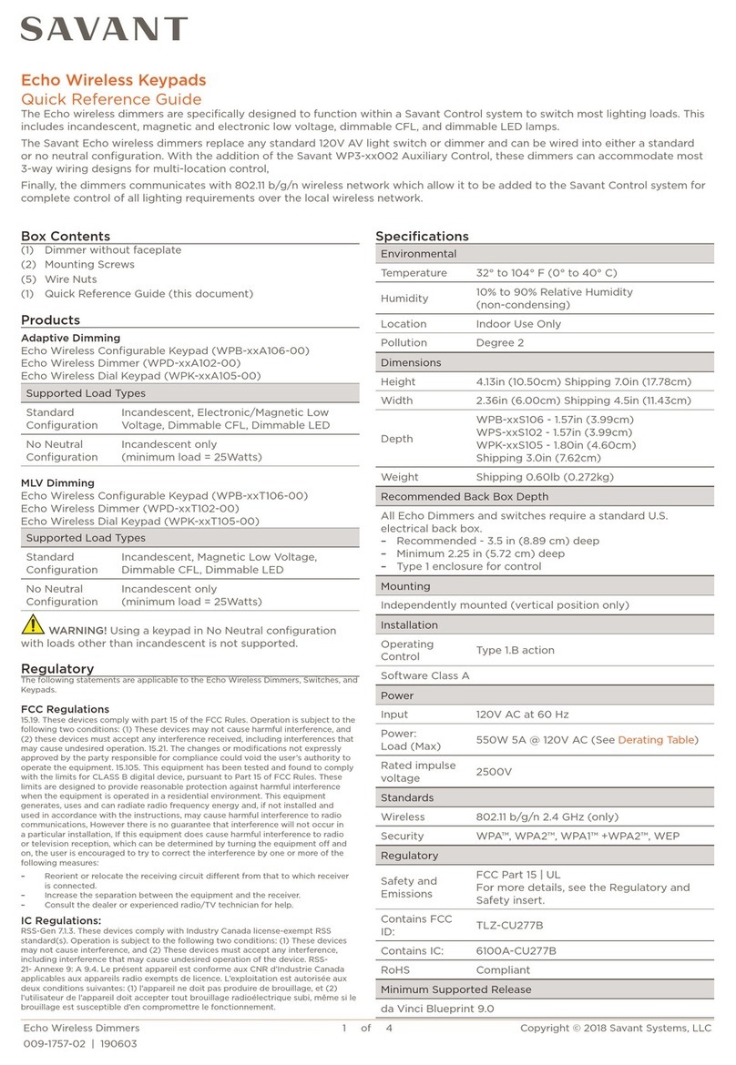
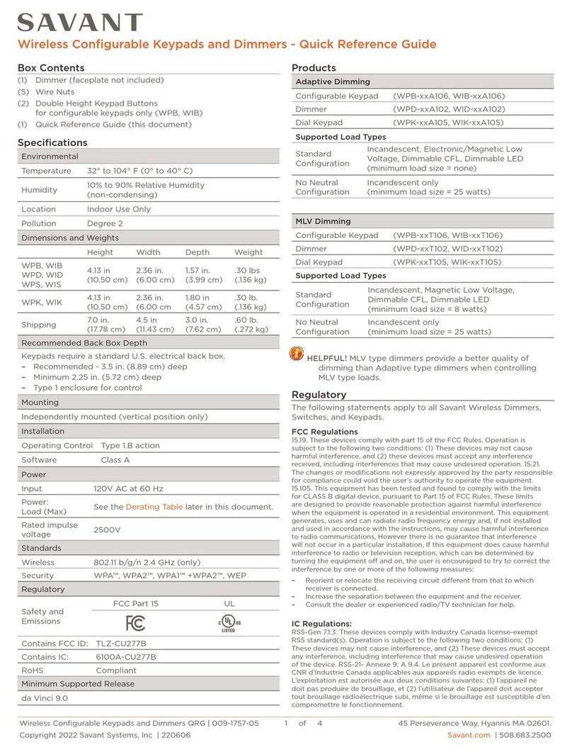
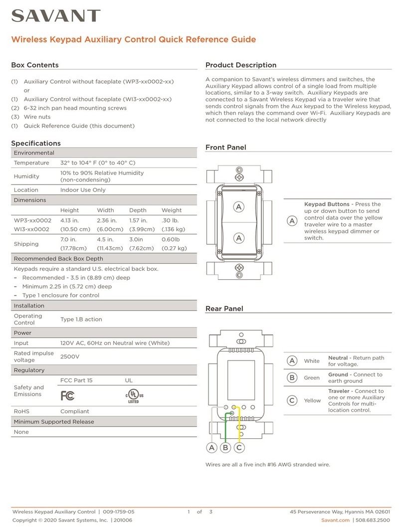
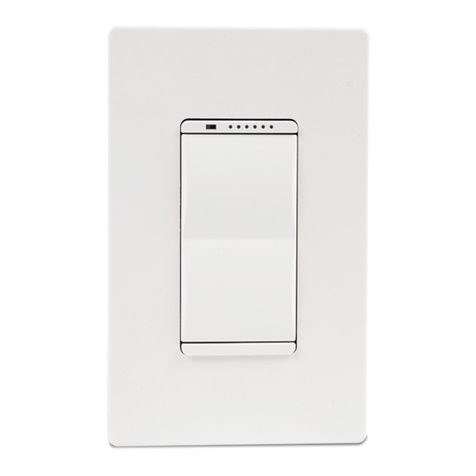
Savant WPX LV06 Series User manual

Wireless Configurable Keypad for DMX Control - QRG 1 of 5 45 Perseverance Way, Hyannis MA 02601.
Copyright© 2021 Savant Systems, Inc. | 009-2075-00 | 211015 Savant.com | 508.683.2500
Echo / Metropolitan Wireless Configurable Keypad for Basic DMX Control
Configurable Keypad - Echo Style (WPX-xxLV06)
Configurable Keypad - Metropolitan Style (WIX-xxLV06)
ProductsBox Contents (WPX-xxLV06, WIX-xxLV06)
Optional Accessories
(1) Keypad (faceplate not included)
(1) 4-pin Cable Control Station Pigtail (064-0417)
(2) Double Height Keypad Buttons (074-0927) - WPX Only
(2) Double Height Keypad Buttons (074-0808) - WIX Only
(1) Product Regulatory Statement (009-1950)
–One to Four Gang Wall Plates (FIx-0S0xxP)
Environmental
Temperature 32° to 104° F (0° to 40° C)
Humidity 10% to 90% Relative Humidity (non-condensing)
Location Indoor Use Only
Specifications
Dimensions and Weights
Length Width Depth Weight
WPX-xxLV06
WIX-xxLV06
4.13 inch
(10.50 cm)
1.72 inch
(4.37 cm)
.97 inch
(2.46 cm)
.30 lb.
(0.13 kg)
Shipping 7.0 inch
(17.78 cm)
4.5 in.
(11.43 cm)
3.0 in.
(7.62 cm)
.60 lb.
(0.27 kg)
Installation Recommendations
Savant recommends as a minimum:
–An open-backed low voltage bracket installed on the interior
walls and a closed-back electrical box on exterior walls.
–An installation depth of at least 1 ¼inches (3.2 cm).
Power
Input 24V DC
Average Power
Consumption 5W
Maximum Power
Consumption 12W
Maximum Wiring (DMX keypad to DMX Driver )
#20 AWG 328 feet (100 meters)
#18 AWG 492 feet (150 meters)
#16 AWG 618 feet (188 meters)
#14 AWG 984 feet (300 meters)
Minimum Supported Release
da Vinci 10.0
Regulatory
Safety and
Emissions
FCC Part 15
Class B CE Mark UKCA
RoHS Compliant
A
B
CDE
A
Ambient Light Sensor - Detects the level of ambient light
in the room and adjusts the brightness of the button and
dimming LEDs. The ambient light sensor is enabled and
disabled in Blueprint’s Lighting and Shade manager.
B
Dimming Level Indicators - These LEDs can indicate any
of the following:
–The power being applied to the load. The LEDs turn
on from left to right as power is increased and switch
o from right to left as power is decreased.
–The power being applied to the load from any scenes
created in Blueprint or the Pro App.
–The status of the keypad during the setup and
provisioning process. See the LED States section.
C
Reset Button
Press and release - Reboots the keypad.
Press and hold - Press and hold for 10 seconds, then
release to perform a factory reset. A factory reset erases
the keypad’s stored address and removes any assigned IP
Addresses.
D
Buttons - Programmable buttons. See the Low Voltage
Deployment Guide for instructions on how to program.
This guide and other lighting information are available on
the Keypad Lighting Documentation Portal in the Savant
Customer Community.
E
Button LEDs - When configured and bound to a Savant
system, the LED’s state is defined by the selection made
in the LED Behavior and LED Color fields in the Lighting
and Shades Device Manager.
Front Panel
Quick Reference Guide

Wireless Configurable Keypad for DMX Control - QRG 2 of 5 45 Perseverance Way, Hyannis MA 02601.
Copyright© 2021 Savant Systems, Inc. | 009-2075-00 | 211015 Savant.com | 508.683.2500
Wiring Diagrams
The keypad’s rear panel includes a 4-pin connection that accepts the supplied keypad station pigtail cable. The connector is keyed to
avoid plugging the connector backward. Use wire-nuts or an approved alternative when making the connections. Wiring for both the
DMX-DRIVER1 (5 meter LED strips) and DMX DRIVER3 (10 meter LED strips) are shown in the diagrams below.
Additional Information
–Savant recommends using the SHA-W1000 cable when making connections between the DMX-DRIVER1 and DMX keypad. Shown in
the diagram above is the SHA-W1000 cable with the recommended wire colors and connections.
–Savant recommends the HLG-240H-24 power supply shown in the diagram. This transformer can supply the 24V DC needed to
power the DMX keypad. However, other power supplies such as the SHA-POWSINGLE transformer or the +/- ports on the SKL-
3040/1010 keypad power and control module can be used.
–See the Maximum Wiring section in the table above when making connections between the DMX Keypad and DMX Driver.
–Up to 32 DMX devices are supported on each DMX keypad. This includes the combination of drivers, lighting fixtures, and LED
strips. Do not exceed 32 RDM devices as listed in the RDM tab of the OLA server.
–Do not run DMX signaling in the same conduit as the high voltage AC lines.
–Fixtures/loads will not illuminate when there is no DMX signal present
–See the DMX Keypad Deployment Guide on the Savant Customer Community for additional wiring diagrams.
WPX/WIX-xxLV06
Back Panel
Wiring for the
WRGB LED
Strip shown
120/240V AC
120-277V AC
DC +24V
G
R
B
W
N = Neutral (White)
L = Hot (Black)
DMX-DRIVER1
N
L
+
+
W/CW
B/WW
GND
D+
D-
G/CW
R/WW
N/C
OUTPUT
INPUT
Blue = Neutral
Green w/Yellow Stripe = Gnd
Brown = Gnd
HLG-240H-24
POWER SUPPLY
-
+D+D-
24V DC Gnd
24V DC Input
D+ (data)
D- (data)
Black
Red
Blue
Yellow
Station Pigtail
Length - 5
½
inches
Gauge - #22 AWG stranded.
SHA-W1000
24V DC
DMX-DRIVER1

Wireless Configurable Keypad for DMX Control - QRG 3 of 5 45 Perseverance Way, Hyannis MA 02601.
Copyright© 2021 Savant Systems, Inc. | 009-2075-00 | 211015 Savant.com | 508.683.2500
DMX-DRIVER3
No Connection
No Connection
No Connection
No Connection
No Connection
D+ (data)
D- (data)
Ground
Pin 3
Pin 4
Pin 5
Pin 6
Pin 7
Pin 8
Pin 2
Pin 1
WPX/WIX-xxLV06
Back Panel
-
+D+D-
120/240V AC
OUTPUT
INPUT
Blue = Neutral
Green w/Yellow Stripe = Gnd
black = V-
+24V DC Input
red = V+
Brown = Gnd
HLG-240H-24
POWER SUPPLY
GND
DMX Input
DMX in/out
118 8
DMX in/out
D-
D+
D-
D+
W2/WW
W1/CW
B/WW
G/CW
R/WW
V+
V+
V-
V-
+
DMX-DRIVER3
Wiring for the
WRGB LED
Strip shown
DC +24V
G
R
B
W
24V DC Gnd
24V DC Input
D+ (data)
D- (data)
Black
Red
Blue
Yellow
Station Pigtail
Length - 5 ½ inches
Gauge - #22 AWG stranded.
SHA-W1000
CAT-5e/6
Pinout for DMX Ports
CAT-5e/6
24V DC
DMX IN
DMX OUT
P3
ON
OFF
DMX IN
DMX OUT
P3
ON
OFF
Set the Dipswitch on the
last fixture in the chain to ON.
(End of Line Terminator)
Daisy-chain connections
between lighting fixtures.
DMX Out → DMX In
DMX
LIGHT
FIXTURE 1
DMX
LIGHT
FIXTURE 2
RJ-45 Connector
(Gold pins facing up)
Pin 1 Pin 8
Additional Information
–Savant recommends using the SHA-W1000 cable when making connections between the DMX-DRIVER3 and DMX keypad. Shown
in the diagram above is the SHA-W1000 cable with the recommended wire colors and connections.
–Savant recommends the HLG-240H-24 power supply shown in the diagram. This transformer can supply the 24V DC needed to
power the DMX keypad and LED driver. However, other power supplies such as the SHA-POWSINGLE transformer or the +/- ports
on the SKL-3040/1010 keypad power and control module can be used.
–See the Maximum Wiring section in the table above when making connections between the DMX Keypad and DMX Driver.
–Up to 32 DMX devices are supported on each DMX keypad. This includes the combination of drivers, lighting fixtures, and LED
strips. Do not exceed 32 RDM devices as listed in the RDM tab of the OLA server.
–Maximum distance of the DMX cable is 1600 feet. This is the total distance daisy-chained through all fixtures.
–Set the dipswitch on the last fixture in the chain to ON. The last fixture is regarded as an end of line terminator.
–Do not run DMX signaling in the same conduit as the high voltage AC lines.
–Fixtures/loads will not illuminate when there is no DMX signal present
–See the DMX Keypad Deployment Guide on the Savant Customer Community for additional wiring diagrams.
The image below shows the DMX-DRIVER3 providing control to both an LED strip and a USAI DMX lighting fixture. Use the diagram
below for reference when connecting the various type loads.

Wireless Configurable Keypad for DMX Control - QRG 4 of 5 45 Perseverance Way, Hyannis MA 02601.
Copyright© 2021 Savant Systems, Inc. | 009-2075-00 | 211015 Savant.com | 508.683.2500
1. At the main breaker panel, switch o the breaker that supplies power to the keypad.
NOTE: Skip steps 2-5 when this is a new installation.
2. Remove the keypad’s wall plate from the wall plate adapter.
3. Unscrew the two #6-32 x ¼inch flat head screws and remove the wall plate adapter.
4. Unscrew the two #6-32 x ¾inch pan head screws and pull out the existing keypad.
5. Unplug the 4-pin connector from the rear of the keypad.
6. Using the wiring diagrams from the previous few pages, connect the wires from the 4-pin connector to the in-wall wires using an
approved wire nut or a similar alternative. If replacing an existing keypad, ensure the connections made to the 4-pin connector are
correct and secure.
7. Plug the pigtail wire into the rear of the keypad. The connector is keyed and can only be plugged one way.
Removal and Installation
8. Insert the keypad into the electrical switch box and secure
using the #6-32 x ¾inch flat head screws provided. DO NOT
use a powered screwdriver. A powered screwdriver can over-
tighten the screws.
9. Install the wall plate adapter using the #6-32 x 1/4 inch screws
supplied with the adapter.
10. Switch on the breaker to apply power to the keypad. The
keypad will go through an initial boot sequence and when the
sequence completes, the six LEDs on the dimming array will
begin blinking white in an alternating pattern. This pattern
indicates the keypad is not currently communicating on the
local Wi-Fi network. See the LED States section on the next
page for more LED sequence information.
11. The next step is to provision the keypad to the local Wi-
Fi network. Information on provisioning is available in the
Wireless Keypad Provisioning Guide. This guide and others can
be located from within the Lighting Documentation Portal on
the Savant Community
Wall Plate and Adapter
Sold Separately
Wall Plate
Adapter Wall Plate
Mounting
Screws
Electrical
Switch Box
12. With the keypad is provisioned, snap the wall plate into the wall plate adapter. The keypad is now ready to be added to a Savant
system. Blueprint programming information is available in the DMX Low Voltage Deployment Guide. This guide is also available from
within the Lighting Documentation Portal on the Savant Community.
Whether installing a new keypad or replacing an existing one, refer to the instructions below.
IMPORTANT NOTES:
–When working with electricity, even low voltage electricity, follow all standard electrical and safety precautions to avoid leaving
exposed or bare wires that can short and cause damage to the equipment or yourself.
–Savant recommends a licensed electrician be used to make the electrical connections. When working with AC voltage, a licensed
electrician is required.

Wireless Configurable Keypad for DMX Control - QRG 5 of 5 45 Perseverance Way, Hyannis MA 02601.
Copyright© 2021 Savant Systems, Inc. | 009-2075-00 | 211015 Savant.com | 508.683.2500
.5s
.5s
REPEAT
Three dimming LEDs alternate left to right.
The keypad can’t communicate with the local wireless network. In this state, no IP Address is assigned.
Use the Savant SmartConnect App to communicate with the keypad over Bluetooth and provision the
keypad to the network.
.5s
.5s
Repeat
Three dimming LEDs on left are solid and three dimming LEDs on the right blink.
The keypad is connected to the local network (IP Address is assigned) but not communicating with the
system Host. Possible reasons why the keypad is not communicating with the Host are:
–No Blueprint configuration was uploaded to the Host.
–The ethernet cable on Host is unplugged or bad.
.5s
.5s
Repeat
Rightmost dimming LED either blinks or remains solid.
The keypad has entered the bootloader mode. The bootloader state typically indicates a firmware
update is in progress.
LED States
HELPFUL INFORMATION! During the setup process, or if the keypad is not functioning in a Savant system, the dimming LEDs are
programmed to blink a specific sequence to indicate the keypad’s state. To find the keypad’s state, press any button on the
keypad, and the dimming LEDs will begin blinking. These LEDs will blink this specific sequence for about 30 seconds and then
stop. After the blinking stops, press any button on the keypad and the LED’s will begin blinking. Once the keypad is connected to
the Wi-Fi network and communicates with the Host (functions normal in a Savant system), the dimming LEDs track against the
device the keypad is controlling.
This manual suits for next models
4
Table of contents
Other Savant Keypad manuals

Savant
Savant WP3 0002 Series User manual

Savant
Savant Metropolitan User manual

Savant
Savant WIK 104 Series User manual

Savant
Savant Echo User manual

Savant
Savant WIK- 104 Series User manual

Savant
Savant WFB LV02 Series User manual

Savant
Savant WPB-LV06 Series User manual

Savant
Savant PWM-ENC3 Quick reference guide

Savant
Savant WPB 106 Series User manual

Savant
Savant WPB-LV02 Series User manual