evertz SC-500E User guide

SC-500E System Controller
System Manual
© Copyright 2009
EVERTZ MICROSYSTEMS LTD.
5288 John Lucas Drive,
Burlington, Ontario, Canada
L7L 5Z9
Phone: +1 905-335-3700
Sales Fax: +1 905-335-3573
Tech Support Phone: +1 905-335-7570
Tech Support Fax: +1 905-335-7571
Web Page: http://www.evertz.com
Version 1.0, October 2009
The material contained in this manual consists of information that is the property of Evertz Microsystems and is
intended solely for the use of purchasers of the Topaz Router. Evertz Microsystems expressly prohibits the use
of this manual for any purpose other than the operation of the device.
All rights reserved. No part of this publication may be reproduced without the express written permission of
Evertz Microsystems Ltd. Copies of this guide can be ordered from your Evertz products dealer or from Evertz
Microsystems.

IMPORTANT SAFETY INSTRUCTIONS
The lightning flash with arrowhead symbol within an equilateral triangle is
intended to alert the user to the presence of uninsulated “Dangerous voltage”
within the product’s enclosure that may be of sufficient magnitude to constitute
a risk of electric shock to persons.
The exclamation point within an equilateral triangle is intended to alert the user
to the presence of important operating and maintenance (Servicing) instructions
in the literature accompanying the product.
•Read and keep these instructions.
•Please heed all warnings and follow all instructions.
•Do not use this apparatus near water
•Clean only with dry cloth.
•Do not block any ventilation openings. Install in accordance with the manufacturer’s
instructions.
•Do not install near any heat sources such as radiators, heat registers, stoves, or other
apparatus (including amplifiers) that produce heat.
•Do not defeat the safety purpose of the polarized or grounding-type plug. A polarized plug has
two blades with one wider than the other. A grounding-type plug has two blades and a third
grounding prong. The wide blade or the third prong is provided for your safety. If the provided
plug does not fit into your outlet, consult an electrician for replacement of the obsolete outlet.
•Protect the power cord from being walked on or pinched particularly at plugs, convenience
receptacles and the point where they exit from the apparatus.
•Only use attachments/accessories specified by the manufacturer
•Unplug this apparatus during lightning storms or when unused for long periods of time.
•Refer all servicing to qualified service personnel. Servicing is required when the apparatus has
been damaged in any way, such as power-supply cord or plug is damaged, liquid has been
spilled or objects have fallen into the apparatus, the apparatus has been exposed to rain or
moisture, does not operate normally, or has been dropped.
WARNING
TO REDUCE THE RISK OF FIRE OR ELECTRIC – SHOCK, DO NOT EXPOSE THIS APPARATUS
TO RAIN OR MOISTURE AND PLUG EACH POWER SUPPLY CORD INTO SEPARATE BRANCH
CIRCUITS EMPLOYING SEPARATE SERVICE GROUNDS
WARNING
DO NOT EXPOSE THIS EQUIPMENT TO DRIPPING OR SPLASHING AND ENSURE THAT NO
OBJECTS FILLED WITH LIQUIDS ARE PLACED ON THE EQUIPMENT
WARNING
TO COMPLETELY DISCONNECT THIS EQUIPMENT FROM THE AC MAINS, DISCONNECT THE
POWER SUPPLY CORD PLUG FROM THE AC RECEPTACLE
WARNING
THE MAINS PLUG OF THE POWER SUPPLY CORD SHALL REMAIN READILY OPERABLE

WARNING
WARNING: Dangerously high voltages are present inside this equipment.
WARNING: This equipment uses power/mains connectors fitted with earth pins. It is most
important as a matter of personal safety that the equipment is properly earthed.
CAUTION: This equipment may have more than one power supply cord. To reduce the risk of electric
shock, disconnect all power supply cords before servicing.
CAUTION: These servicing instructions are for use by qualified personnel only. To reduce the risk of
electric shock, do not perform any servicing other than that contained in the operating instructions unless
you are qualified to do so. Refer all servicing to qualified personnel.
CAUTION: To reduce the risk of electric shock, plug each power supply cord into separate branch circuits
employing separate service grounds.
NEVER use flammable or combustible chemicals for cleaning components.
NEVER operate this product with any covers removed.
NEVER wet the inside of this product with any liquid.
NEVER bypass any fuse or replace any fuse with a value or type other than those specified.
NEVER operate this product in an explosive atmosphere.
NEVER block the airflow through ventilation slots.
NEVER expose this product to extremely low or high temperatures.
This product complies with the requirements of the product family standards for video, audio, audio-visual
entertainment, and lighting control apparatus for professional use as mentioned below.
EN60950 Safety
EN55103-1: 1996 Emission
EN55103-2: 1996 Immunity
EN504192 2005
Waste electrical products should
not be disposed of with household
waste. Contact your Local
Authority for recycling advice
Quartz Electronics Ltd
Tested to comply with
FCC Standards
For Home or Office Use
This device complies with part 15 of the FCC Rules.
Operation is subject to the following two conditions:
1) This device may cause harmful interference, and
2) This device must accept any interference received,
including interference that may cause undesired
operation.


SC-500E System Controller
Revision 1.0 Page i
REVISION HISTORY
REVISION DESCRIPTION DATE
1.0 First release Oct 09
Information contained in this manual is believed to be accurate and reliable. However, Evertz assumes no responsibility for the use thereof nor
for the rights of third parties, which may be effected in any way by the use thereof. Any representations in this document concerning
performance of Evertz products are for informational use only and are not warranties of future performance, either express or implied. The only
warranty offered by Evertz in relation to this product is the Evertz standard limited warranty, stated in the sales contract or order confirmation
form.
Although every attempt has been made to accurately describe the features, installation and operation of this product in this manual, no
warranty is granted nor liability assumed in relation to any errors or omissions unless specifically undertaken in the Evertz sales contract or
order confirmation. Information contained in this manual is periodically updated and changes will be incorporated into subsequent editions. If
you encounter an error, please notify Evertz Customer Service department. Evertz reserves the right, without notice or liability, to make
changes in equipment design or specifications.

SC-500E System Controller
Page II Revision 1.0
This page left intentionally blank

SC-500E System Controller
Revision 1.0 Page iii
TABLE OF CONTENTS
1. OVERVIEW ........................................................................................................................1
1.1. HOW TO USE THIS MANUAL............................................................................................... 2
1.2. DEFINITIONS ......................................................................................................................... 3
2. INSTALLATION .................................................................................................................6
2.1. UNPACKING .......................................................................................................................... 6
2.2. PHYSICAL INSTALLATION .................................................................................................. 6
2.2.1. System Controller ....................................................................................................... 6
2.3. ELECTRICAL CONNECTIONS ............................................................................................. 7
2.4. STANDARD CONFIGURATION ............................................................................................ 7
2.4.1. Power 1 PSU 12VDC Input......................................................................................... 7
2.4.2. Q-LINK 1, Q-LINK 2, Q-LINK 3, Q-LINK 4 Ports......................................................... 7
2.4.3. Serial 1, Serial 2, Serial 3, Serial 4 RS-422/RS-232 Ports ......................................... 7
2.4.4. Alarm Connection ....................................................................................................... 7
2.4.5. Ethernet Connection ................................................................................................... 7
2.4.5.1. Connecting to an Ethernet Network ............................................................. 8
2.5. OPTIONAL CUSTOMIZED CONFIGURATIONS................................................................... 9
2.5.1. Power 2 PSU 12 VDC Input........................................................................................ 9
2.5.2. Serial 5, 6, 7 RS-422/RS-232 ..................................................................................... 9
2.6. ABOUT Q-LINK...................................................................................................................... 9
3. TECHNICAL DESCRIPTION ...........................................................................................11
3.1. SPECIFICATIONS................................................................................................................ 11
3.2. PHYSICAL............................................................................................................................ 11
3.3. ELECTRICAL ....................................................................................................................... 11
4. OPERATION ....................................................................................................................12
4.1. SYSTEM OVERVIEW........................................................................................................... 12
4.1.1. Interfacing Ethernet Control Panels with Quartz Routers ......................................... 12
4.1.2. Interfacing Q-Link Control Panels with Evertz Routers............................................. 12
4.1.3. Interfacing Q-Link Control Panels with EQX Server ................................................. 12
4.2. SYSTEM COMPONENTS .................................................................................................... 12
4.3. SYSTEM CONFIGURATION................................................................................................ 13
4.3.1. Frame Address Switches .......................................................................................... 13
4.3.2. DIP Switch settings ................................................................................................... 13
4.3.3. Serial Port ................................................................................................................. 13
4.3.4. Status LEDs ..............................................................................................................14
4.3.4.1. RESET LED ............................................................................................... 14
4.3.4.2. PROC HAPPY LED.................................................................................... 14
4.3.4.3. MAJOR ERR LED ...................................................................................... 14

SC-500E System Controller
Page IV Revision 1.0
4.3.4.4. GENERAL ERR LED.................................................................................. 14
4.3.4.5. XPT LED .................................................................................................... 14
4.3.4.6. ACT LED .................................................................................................... 14
4.3.4.7. SPEED LED ............................................................................................... 14
4.3.4.8. LINK LED ................................................................................................... 15
4.3.5. RS-422 and RS-232 RJ-45 Pin Assignment ............................................................. 15
4.3.6. RS-485/RS-422 Compatibility ................................................................................... 15
4.3.7. Ethernet Port............................................................................................................. 15
5. CONFIGURING THE SYSTEM USING WINSETUP ....................................................... 17
5.1. SPECIAL INTERFACES ...................................................................................................... 21
5.1.1. Control Panel Ethernet Interface............................................................................... 21
5.1.2. Control panel Q-Link Interface .................................................................................. 21
5.1.3. Router Ethernet Interface.......................................................................................... 22
5.1.4. Router Q-Link Interface............................................................................................. 23
5.1.5. Serial Interface.......................................................................................................... 23
5.1.6. Ethernet Interface ..................................................................................................... 24
5.1.7. Configuring Routers to Communicate with the SC-500E .......................................... 24

SC-500E System Controller
Revision 1.0 Page v
Figures
Figure 1-1: SC-500E System Controller ...........................................................................................................1
Figure 2-1: Rear View of SC-500E ...................................................................................................................7
Figure 2-2: Daisy Chain Method .....................................................................................................................10
Figure 4-1: Front Edge Controls .....................................................................................................................13
Figure 5-1: WinSetup Configuration Editor.....................................................................................................17
Figure 5-2: WinSetup Frame Editor ................................................................................................................18
Figure 5-3: WinSetup Source Definition .........................................................................................................19
Figure 5-4: WinSetup Panel Configuration .....................................................................................................20
Figure 5-5: Ethernet Panels Port Settings ......................................................................................................21
Figure 5-6: Q-Link Hosted Panels Port Settings.............................................................................................22
Figure 5-7: Ethernet Router Port Settings ......................................................................................................22
Figure 5-8: Q-Link Router Port Settings .........................................................................................................23
Figure 5-9: Serial Port Settings.......................................................................................................................23
Figure 5-10: Ethernet Port Settings ................................................................................................................24
Tables
Table 2-1: Standard RJ-45 Wiring Colour Codes .............................................................................................8
Table 4-1: DIP Switch Functions ....................................................................................................................13
Table 4-2: RS-232 & RS-422 RJ45 Pin Assignment ......................................................................................15
Table 4-3: Comparing Various Pin Configurations .........................................................................................16

SC-500E System Controller
Page VI Revision 1.0
This page left intentionally blank

SC-500E System Controller
Revision 1.0 Page 1
1. OVERVIEW
The SC-500E system controller is a platform designed to manage all communication and interface
requirements for small to medium routing systems.
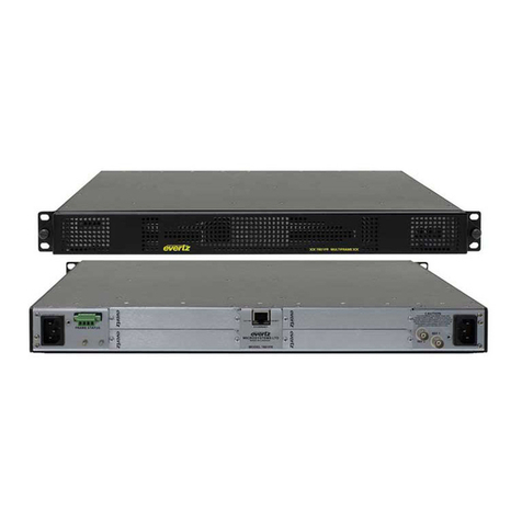
Housed in a 1RU frame the SC-500E system controller manages the communication between multiple
Evertz/Quartz products and third party equipment. It can also be configured to provide communication
translations between Q-Link, RS-422/RS-232 and Ethernet.
The SC-500E is powered from a single external power supply that connects to the frame via a secure
bayonet locking connector. A redundant external power supply can also be fitted if required.
The SC-500E in its standard configuration provides two Q-Link ports, two RS-422/RS-232 serial ports
and a single Ethernet port. There are also two additional ports that can be used as a Q-Link port or a
RS-422/RS-232 serial port.
The SC-500E is capable of supporting up to 32 router control panels simultaneously. The panels can
be connected to the SC-500E via Q-Link, Ethernet, or a mixture of both.
The SC-500E is capable of controlling up to 16 independent routers on 16 individual levels.
Figure 1-1: SC-500E System Controller
FEATURES:
•Provides an Ethernet interface for Quartz routers that do not have an Ethernet connection to
interface with control panels via Ethernet
•Provides a Q-Link interface for Evertz routers that do not have a Q-Link connection to interface
with control panels via Q-Link
•Provides an interface to EQX-SERVER for control panels via Q-Link

SC-500E System Controller
Page 2 Revision 1.0
1.1. HOW TO USE THIS MANUAL
This manual will assist you in the use of the SC-500E, and contains all the necessary information to
successfully operate this product. If further product information or assistance is required, please contact
Evertz or your local Evertz/Quartz distributor.
This manual is organized into 5 sections: Overview, Installation, Technical Description, System
Overview, and Configuration
Section 1: Contains a brief overview of the SC-500E operation, features and a glossary to define
concepts and terms used throughout the remainder of the manual.
Section 2: Provides instructions on how to unpack, install and setup the SC-500E.
Section 3: Provides technical specifications and information on configuring the connector pin-outs
of the SC-500E system.
Section 4: Describes how to control the SC-500E.
Section 5: Provides instructions on how to configure the SC-500E.
"This symbol is intended to alert the user to important operating instructions.
The exclamation point within an equilateral triangle is intended to alert the
user to the presence of important safety related operating and maintenance
(Servicing) instructions in this manual.

SC-500E System Controller
Revision 1.0 Page 3
1.2. DEFINITIONS
4:2:2: The sampling ratio used in the HDTV digital video signal. For every 4 samples of
luminance there are 2 samples each of R-Y (Red minus Luminance) and B-Y (Blue
minus Luminance).
16x9: A wide screen television format such as HDTV in which the aspect ratio of the screen
is 16 units wide by 9 high as opposed to the 4x3 of normal TV.
AES/EBU: (Sometimes abbreviated as AES) Refers to the digital audio standard (AES3-1992) set
by the Audio Engineering Society and European Broadcast Union, and used by most
forms of digital audio from CDs to professional digital video.
ASPECT RATIO: The ratio of width to height in a picture. Theatre screens generally have an
aspect ratio of 1.85 to 1, widescreen TV (16x9) is 1.77 to 1, and normal TV (4x3) is
1.33 to 1.
CCIR (International Radio Consultative Committee): An international standards committee. (This
organization is now known as ITU.)
CCIR-601: See ITU-R601.
CLIFF EFFECT: (Also referred to as the ‘digital cliff’) This is a phenomenon found in digital video
systems that describes the sudden deterioration of picture quality when due to
excessive bit errors, often caused by excessive cable lengths. The digital signal will
be perfect even though one of its signal parameters is approaching or passing the
specified limits. At a given moment however, the parameter will reach a point where
the data can no longer be interpreted correctly, and the picture will be totally
unrecognizable.
COMPONENT ANALOG: The non-encoded output of a camera, video tape recorder, etc.,
consisting of the three primary colour signals: red, green, and blue (RGB) that together
convey all necessary picture information. In some component video formats these
three components have been translated into a luminance signal and two colour
difference signals, for example Y, B-Y, R-Y.
COMPONENT DIGITAL: A digital representation of a component analog signal set, most often Y,
B-Y, R-Y. The encoding parameters are specified by ITU-R709 for HDTV signals.
SMPTE 274M and SMPTE 296M specify the parallel interface.
COMPOSITE ANALOG: An encoded video signal such as NTSC or PAL video that includes
horizontal and vertical synchronizing information.
COMPOSITE DIGITAL: A digitally encoded video signal, such as NTSC or PAL video that
includes horizontal and vertical synchronizing information.

SC-500E System Controller
Page 4 Revision 1.0
DROP FRAME: In NTSC systems, where the frame rate is 29.97002618 frames per second, the drop
frame mode permits time of day indexing of the frame numbers by dropping certain
frame numbers. Specifically frames 0, and 1 at the beginning of each minute except
minutes 0,10,20,30,40, & 50, are omitted, to compensate for an approximate timing
error of 108 frames (3 seconds 18 frames) per hour. A flag bit is set in the time code
to signal when the drop frame mode is in effect.
EBU (European Broadcasting Union): An organization of European broadcasters that among
other activities provides technical recommendations for the 625/50 line television
systems.
EMBEDDED AUDIO: Digital audio is multiplexed onto a serial digital video data stream.
ITU: The United Nations regulatory body governing all forms of communications. ITU-R
(previously CCIR) regulates the radio frequency spectrum, while ITU-T (previously
CCITT) deals with the telecommunications standards.
ITU-R601: An international standard for standard definition component digital television from
which was derived SMPTE 125M and EBU 3246-E standards. ITU-R601 defines the
sampling systems, matrix values and filter characteristics for Y, B-Y, R-Y and RGB
component digital television signals.
NTSC: National Television Standards Committee established the television and video
standard in use in the United States, Canada, Japan and several other countries.
NTSC video consists of 525 horizontal lines at a field rate of approximately 60 fields
per second. (Two fields equals one complete Frame). Only 487 of these lines are used
for picture. The rest are used for sync or extra information such as VITC and Closed
Captioning.
PAL: Phase Alternating Line. The television and video standard in use in most of Europe.
Consists of 625 horizontal lines at a field rate of 50 fields per second. (Two fields
equals one complete Frame). Only 576 of these lines are used for picture. The rest are
used for sync or extra information such as VITC and Teletext.
PIXEL: The smallest distinguishable and resolvable area in a video image. A single point on
the screen. In digital video, a single sample of the picture. Derived from the words
picture element.
SMPTE (Society of Motion Picture and Television Engineers): A professional organization that
recommends standards for the film and television industries.
SMPTE 12M: The SMPTE standard for Time and address code. SMPTE 12M defines the
parameters required for both linear and vertical interval time codes.
SMPTE 125M: The SMPTE standard for bit parallel digital interface for component video signals.
SMPTE 125M defines the parameters required to generate and distribute component
video signals on a parallel interface.
SMPTE 259M-C: The SMPTE standard for 525 and 625 line serial digital component and
composite interfaces.

SC-500E System Controller
Revision 1.0 Page 5
SMPTE 272M: The SMPTE standard for embedding audio in serial digital standard definition
(SMPTE 259M-C) video signals.
SMPTE 274M: The SMPTE standard for bit parallel digital interface for high definition component
video signals with an active picture of 1080 lines x 1920 pixels.
SMPTE 276M: The SMPTE standard for transmission of AES/EBU Digital Audio Signals Over Coaxial
Cable.
SMPTE 292M: The SMPTE standard for high definition serial digital component interfaces.
SMPTE 296M: The SMPTE standard for bit parallel digital interface for high definition component
video signals with an active picture of 720 lines x 1280 pixels.
SMPTE 299M: The SMPTE standard for embedding audio in serial digital high definition
(SMPTE 292M) video signals.
TRS: Timing reference signals used in composite digital systems. (It is four words long).
TRS-ID: Abbreviation for "Timing Reference Signal Identification". A reference signal used to
maintain timing in composite digital systems. (It is four words long.)

SC-500E System Controller
Page 6 Revision 1.0
2. INSTALLATION
2.1. UNPACKING
Remove the equipment carefully from the boxes and check against the Packing List supplied with each
unit. This shows what items have been shipped against your order and includes all options.
Any error should be reported to your supplier immediately. After you have unpacked the equipment
please save all the packing material as this could be useful in the future if the unit needs to be returned
for maintenance.
Check each item supplied for transit damage. Any damage should be reported in detail to your supplier.
You must state the serial number of the unit which can be found on the rear of the frame. Check that
power cords supplied are suitable for your country and that the equipment is compatible with your
mains (line) voltage.
The SC-500E range uses a common external PSU ‘brick’ that is auto-ranging and converts nominal
115V or 230V AC mains voltages to safe 12V DC. This then connects to the SC-500E where any
internally required voltages are generated. The external PSU has an IEC inlet and approximate 1.7m
of DC lead terminated in a two-pin bayonet style connector.
IEC connectors have an earth pin and as a matter of safety this earth pin must be connected to a solid
ground to ensure a proper earth connection.
In the UK, equipment is supplied with a power cord already fitted with a 3 pin mains plug. Should the
lead be re-wired then please make connections using the colour code below:
•Brown = Live (Line or Phase)
•Blue = Neutral (Return)
•Green/Yellow =Earth (Ground)
There is no power switch on the unit so it is essential that the power cord is removed before
commencing to service the unit.
All SC-500E PSU’s are auto-ranging and no adjustments are required.
2.2. PHYSICAL INSTALLATION
2.2.1. System Controller
All units are designed for mounting in standard 19” equipment racks. The depth of the frames is 260mm
(approx.) excluding connectors. In addition, allowance must be made for the cables to be installed at
the rear of the frame.
Overall power dissipation is very low and cooling is by natural convection.
Do not place the SC-500E directly above very hot equipment or in sealed equipment racks that are not
adequately cooled.

SC-500E System Controller
Revision 1.0 Page 7
2.3. ELECTRICAL CONNECTIONS
Figure 2-1: Rear View of SC-500E
2.4. STANDARD CONFIGURATION
The following are the standard options that are supplied with the unit. Further options can be added
depending on the system requirements.
2.4.1. Power 1 PSU 12VDC Input
This is the main 12 Volt DC input. The SC-500E is supplied with the external power supply unit (PSU)
QT-PS. Before using, please check that you have been supplied with the correct unit. The PSU does
not contain any serviceable parts and for safety reasons should not be opened as there is a significant
risk of electric shock. A redundant external power supply can also be fitted, if required (see section
2.5).
2.4.2. Q-LINK 1, Q-LINK 2, Q-LINK 3, Q-LINK 4 Ports
These are Q-Link ports. The sockets are a standard BNC coaxial type. Q-Link is a unique network that
interconnects Evertz/Quartz routers and remote control panels. It uses a standard 75ohm video cable
that daisy-chains from frame-to-frame and panel-to-panel. A ‘T-piece’ connector allows any control
panel to be removed from the network without disruption.
2.4.3. Serial 1, Serial 2, Serial 3, Serial 4 RS-422/RS-232 Ports
These are RS-422/RS-232 serial ports and are fitted as standard. The sockets are RJ-45 connections.
"
Note: Q-LINK 3 and Serial 3 share the same communications lines so only one of
the two ports can be used at any one time.
"
Note: Q-LINK 4 and Serial 4 share the same communications lines so only one of
the two ports can be used at any one time.
2.4.4. Alarm Connection
This connection is used to provide an alarm if there is a complete power failure of the unit. This is an
RJ45 connection.
2.4.5. Ethernet Connection
This is a standard RJ-45 Ethernet connection. The socket is an RJ-45 type. The port is compatible with
a 10BaseT network running TCP/IP protocol.

SC-500E System Controller
Page 8 Revision 1.0
2.4.5.1. Connecting to an Ethernet Network
The SC-500E uses 10Base-T (10 Mbps), 100Base-TX (100 Mbps) or Gigabit (1Gbps) twisted pair
Ethernet cabling systems. When connecting for 10Base-T systems, category 3, 4, or 5 UTP cable as
well as EIA/TIA – 568 100ΩSTP cable may be used. When connecting for 100Base-TX systems,
category 5 UTP cable is required. The cable must be “straight-through” with a RJ-45 connector at each
end. Establish the network connection by plugging one end of the cable into the RJ-45 receptacle of
the SC-500E and the other end into a port of the supporting hub.
The straight-through RJ-45 cable can be purchased or can be constructed using the pin-out
information in Table 2-1. A colour coded wiring table is provided in Table 2-1 for the current RJ-45
standards (AT&T 258A or EIA/TIA 258B colour coding shown). Also refer to the notes following the
table for additional wiring guide information.
Pin # Signal EIA/TIA 568A AT&T 258A or
EIA/TIA 568B
10BaseT
or 100BaseT
1 Transmit + White/Green White/Orange X
2 Transmit – Green/White or White Orange/White or Orange X
3 Receive + White/Orange White/Green X
4 N/A Blue/White or Blue Blue/White or Blue Not used (required)
5 N/A White/Blue White/Blue Not used (required)
6 Receive – Orange/White or Orange Green/White or Green X
7 N/A White/Brown White/Brown Not used (required)
Pin
1
8 N/A Brown/White or Brown Brown/White or Brown Not used (required)
Table 2-1: Standard RJ-45 Wiring Colour Codes
Note the following cabling information for this wiring guide:
•Only two pairs of wires are used in the 8-pin RJ-45 connector to carry Ethernet signals.
•Even though pins 4, 5, 7 and 8 are not used, it is mandatory that they be present in the cable.
•10BaseT and 100BaseTX use the same pins (a crossover cable made for one will also work with
the other).
•Pairs may be solid colours and not have a stripe.
•Category 5 cable must use Category 5 rated connectors.
The maximum cable run between the router and the supporting hub is 300 ft (90 m). The maximum
combined cable run between any two end points (i.e. router and PC/laptop via network hub) is 675 feet
(205 m).
Devices on the Ethernet network continually monitor the receive data path for activity as a means of
checking that the link is working correctly. When the network is idle, the devices also send a link test
signal to one another to verify link integrity.

SC-500E System Controller
Revision 1.0 Page 9
2.5. OPTIONAL CUSTOMIZED CONFIGURATIONS
2.5.1. Power 2 PSU 12 VDC Input
This is the redundant power supply input. The power supply can be supplied as an option. Use only the
approved power supply unit QT-PS. The part number for this unit is PSU-S-105. The use of non-
approved power supply units might have unpredictable results and may cause damage.
2.5.2. Serial 5, 6, 7 RS-422/RS-232
These are standard RS-422/RS-232 ports and the socket is an RJ-45. These ports are currently
unsupported.
2.6. ABOUT Q-LINK
Quartz routers use a communication system called Q-Link that allows routers and panels to be
connected together using a single coaxial video cable.
As standard, routers and panels have one Q-Link port for connection to other Quartz products. They
also have one or two optional serial (RS-422/RS-232) ports for connection to third party equipment.
The daisy chained Q-Link system is simple to install and has a connection limit of 64 devices. Each unit
being connected to the Q-Link has its own address switch, which is set up as part of the system
configuration. The maximum cable length is 500m.
Each end of the link must be terminated in 75.
WARNING: The installer must fit a 75Ωterminator at each end of the cable.
This daisy-chain method ensures the best transmission quality of the control signals down the cable.
Shortcuts that might save cable, such as running stubs to some panels, are not recommended as this
may under certain circumstances cause data errors.

SC-500E System Controller
Page 10 Revision 1.0
Figure 2-2: Daisy Chain Method
Table of contents
Other evertz Controllers manuals
Popular Controllers manuals by other brands

Cool Components
Cool Components TC-ASC-2 installation instructions

Doepke
Doepke Dupline DNP 4 operating instructions

Metron Eledyne
Metron Eledyne MP300 manual

Kyocera
Kyocera CPR 12-15 datasheet

Glentronics
Glentronics PHCC Pro Series Instruction manual & safety warnings

Baelz Automatic
Baelz Automatic BA 375-E42 operating instructions