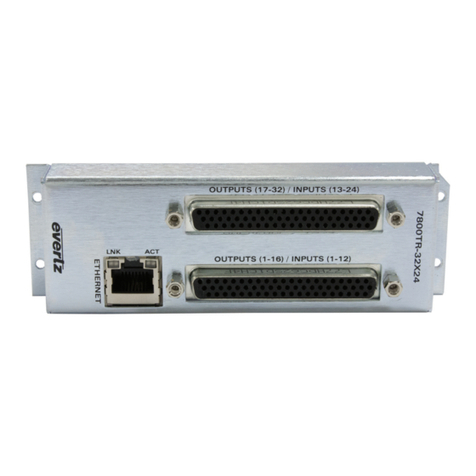
evertz VistaLINK 7801FC User manual

7801 MultiFrame Manual
7801FC VistaLINK®Frame Controller
Revision 1.0 Page - i
TABLE OF CONTENTS
1. OVERVIEW.................................................................................................................................. 1
2. INSTALLATION............................................................................................................................ 2
2.1. REAR PANEL CONNECTIONS............................................................................................ 2
2.1.1. Ethernet Connection ..................................................................................................2
2.1.2. Serial I/O Connections............................................................................................... 4
2.2. REPLACING THE BATTERY............................................................................................... 4
2.2.1. Safety Guidelines and Precautions concerning the Use of 3V Lithium Batteries............4
3. SPECIFICATIONS........................................................................................................................ 5
ETHERNET.................................................................................................................................. 5
3.1. ELECTRICAL ...................................................................................................................... 5
3.2. PHYSICAL (NUMBER OF SLOTS)....................................................................................... 5
4. STATUS LEDS ............................................................................................................................ 6
4.1. MODULE STATUS LEDS ....................................................................................................6
4.2. ETHERNET STATUS LEDS ................................................................................................ 6
5. JUMPERS.................................................................................................................................... 7
5.1. SELECTING WHETHER LOCAL FAULTS WILL BE MONITORED BY THE GLOBAL
FRAME STATUS ................................................................................................................. 7
5.2. CONFIGURING THE MODULE FOR FIRMWARE UPGRADES............................................. 7
6. CONFIGURING THE FRAME CONTROLLER............................................................................... 8
6.1. ESTABLISHING COMMUNICATION WITH THE FRAME CONTROLLER............................. 8
6.1.1. Connecting the Computer to the Card Edge Serial Port...............................................8
6.1.2. Terminal Program Setup............................................................................................ 8
6.2. CONFIGURING THE NETWORK SETTINGS....................................................................... 9
6.2.1. Network Setup......................................................................................................... 10
6.2.2. SNMP Setup........................................................................................................... 12
6.2.2.1. SNMP V1 Setup ......................................................................................... 12
6.2.2.2. SNMP V3 Setup ......................................................................................... 13
6.2.3. Exiting the Setup Menu............................................................................................ 15
7. UPGRADING THE FRAME CONTROLLER IMAGE VISTALINK®................................................ 17
Follow these instructions to establish a connection to the Frame Controller and program a local IP
address to permit Vistalink Pro acess for setup and frame sync timing

7801 MultiFrame Manual
7801FC VistaLINK®Frame Controller
Page - ii Revision 1.0
7.1. PROCEDURES FOR UPGRADING THE FRAME CONTROLLER IMAGE VISTALINK®.......17
7.2. REMOTE UPGRADE PROCEDURE USING VISTALINK®...................................................17
7.2.1. Downloading the 7801FC Frame Controller Image.....................................................17
7.2.2. Upgrading the Frame Controller Image using VistaLINK®...........................................18
7.3. SERIAL CARD EDGE UPGRADE PROCEDURE ................................................................19
7.3.1. Downloading Upgrade Files ......................................................................................20
7.3.2. Linking the Frame Controller to the Network Adapter .................................................20
7.3.3. Connecting the Computer to the Card Edge Serial Port..............................................20
7.3.4. Setting the 7801FC Frame Controller to Upgrade Mode.............................................20
7.3.5. Viewing Startup Information......................................................................................20
7.3.6. Upgrading the 7801FC Boot Loader..........................................................................21
7.3.7. Upgrading the 7801FC Frame Controller...................................................................21
8. WEBEASY®WEB INTERFACE...................................................................................................24
8.1. UPGRADING CARDS USING WEBEASY®..........................................................................25
8.1.1. Upgrading Modules Using WebEASY®......................................................................25
8.1.2. Upgrading 7801FC Using WebEASY®......................................................................26
Figures
Figure 1-1: 7801FC Block Diagram.....................................................................................................1
Figure 2-1: 7801FR Rear Panel..........................................................................................................2
Figure 2-2: Crossover Cable Wiring Diagram ......................................................................................3
Figure 4-1: 7801FC Status LED Location............................................................................................6
Figure 5-1 : Location of Jumpers ........................................................................................................7
Figure 7-1: FC shown in the Hardware Tree......................................................................................18
Figure 7-2: Control Tab for the FC Configuration View.......................................................................19
Figure 7-3: Send File Window..........................................................................................................21
Figure 8-1: WebEASY®Home Page.................................................................................................24
Figure 8-2: WebEASY®Firmware Upgrade Page..............................................................................25
Figure 8-3: WebEASY®Firmware Upgrade Page for 7801FC............................................................26
Tables
Table 2-1: Standard RJ45 Wiring Colour Codes for “Straight Through” Cables .....................................2
Table 2-2: Serial I/O Connector Pin Definitions....................................................................................4
Table 6-1: Upgrade Cable (WA-S76)..................................................................................................8
Table 6-2: Port Settings for Terminal Program Setup...........................................................................8

7801 MultiFrame Manual
7801FC VistaLINK®Frame Controller
Revision 1.0 Page - iii
REVISION HISTORY
REVISION
DESCRIPTION
DATE
1.0
First release
Jan 2014
Information contained in this manual is believed to be accurate and reliable. However, Evertz assumes no responsibility for the use thereof nor for the
rights of third parties, which may be affected in any way by the use thereof. Any representations in this document concerning performance of Evertz
products are for informational use only and are not warranties of future performance, either expressed or implied. The only warranty offered by Evertz
in relation to this product is the Evertz standard limited warranty, stated in the sales contract or order confirmation form.
Although every attempt has been made to accurately describe the features, installation and operation of this product in this manual, no warranty is
granted nor liability assumed in relation to any errors or omissions unless specifically undertaken in the Evertz sales contract or order confirmation.
Information contained in this manual is periodically updated and changes will be incorporated into subsequent editions. If you encounter an error,
please notify Evertz Customer Service department. Evertz reserves the right, without notice or liability, to make changes in equipment design or
specifications.

7801 MultiFrame Manual
7801FC VistaLINK®Frame Controller
Page - iv Revision 1.0
This page left intentionally blank

7801 MultiFrame Manual
7801FC VistaLINK®Frame Controller
Revision 1.0 Page - 1
1. OVERVIEW
The 7801FC VistaLINK® Frame Controller card provides a single point of access to communicate with
VistaLINK®-capable modules in the 7801FR frame. The 7801FC VistaLINK®Frame Controller provides a
10Base-T/100Base-TX/1000Base-T Ethernet port, and communication is facilitated through the use of
Simple Network Management Protocol (SNMP).
The 7801FC VistaLINK®Frame Controller handles all SNMP communications between the frame
(7801FR) and the network manager (NMS), and serves as a gateway to individual cards in the frame.
Features:
•Complies with IEEE 802.3 1000Base-T, 100Base-TX and 10Base-T Ethernet standards
•1000Mb/s, 100Mb/s or 10Mb/s Ethernet data transfer, selected by auto-negotiation
•Full-duplex or half-duplex operation, selected by auto-negotiation
•RJ-45 connector for network cable connection
•Card edge LEDs indicate module fault, microprocessor state, activity and link status
•Rear panel LEDs indicate Ethernet link, activity and speed
•Supports “ftp” upgrades for frame-wide firmware upgrades (product specific)
•Includes VistaLINK® PRO (VLPRO-C) module software configuration tool
•Provides frame/chassis status information through VistaLINK® including power supply status, frame
status, card insertion/removal counters and version information
Figure 1-1: 7801FC Block Diagram

7801 MultiFrame Manual
7801FC VistaLINK®Frame Controller
Page - 2 Revision 1.0
2. INSTALLATION
The 7801FC Frame Controller module is installed into a 7801FR frame.
MADE IN CANADA
LN/ ACT10/100
ETHERNET
3
4
1
2
TH IS EQU IPM ENT HA S M ORE THAN O NE
POW ER SUPPLY C ORD. T O REDU CE RISK O F
ELECTRI C SHO CK GROU ND ING OF T HE CEN TER
PIN O FPO WER SUPPLY CORD PLU GS MU ST BE
M AIN TAINED. DI SCON NECT BOT H POWER
SUPPLY CORDS BEFORE SERV ICIN G
Figure 2-1: 7801FR Rear Panel
2.1. REAR PANEL CONNECTIONS
2.1.1. Ethernet Connection
The 7801FC is designed to be used with 10Base-T (10 Mbps), 100Base-TX (100 Mbps) and 1000Base-T
(1000Mbps) twisted pair Ethernet cabling systems. When connecting for 10Base-T systems, category 3,
4, or 5 UTP cable as well as EIA/TIA – 568 100ΩSTP cable may be used. When connecting for
100Base-TX systems, category 5 UTP cable is required. When connecting for 1000Base-T system,
category 5, 5e, 6, or 7 UTP cable is required. The cable must be “straight-through” with a RJ-45 connector
at each end (See Table 2-1). Make the network connection by plugging one end of the cable into the RJ-45
receptacle of the 7801FC and the other end into a port of the supporting hub. When connecting a 7801FC
directly to the Ethernet port on a computer you will have to use a “crossover” cable as shown in Figure 2-2.
The straight-through RJ-45 cable can be purchased or can be constructed using the pinout information in
Table 2-1. A colour code wiring table is provided in Table 2-1 for the current RJ-45 standards (AT&T 258A
or EIA/TIA 258B colour coding shown). Also refer to the notes following the table for additional wiring
guide information.
Pin 1
Pin # SignalEIA/TIA 568A
AT&T 258A or
EIA/TIA 568B
10BaseT
or 100BaseT
1
Transmit +
White/Green
White/Orange
X
2
Transmit –
Green/White or White
Orange/White or Orange
X
3
Receive +
White/Orange
White/Green
X
4
N/A
Blue/White or Blue
Blue/White or Blue
Not used (required)
5
N/A
White/Blue
White/Blue
Not used (required)
6
Receive –
Orange/White or Orange
Green/White or Green
X
7
N/A
White/Brown
White/Brown
Not used (required)
8
N/A
Brown/White or Brown
Not used (required)
Table 2-1: Standard RJ45 Wiring Colour Codes for “Straight Through” Cables
Note the following cabling information for this wiring guide:
•Only two pairs of wires are used in the 8-pin RJ-45 connector to carry Ethernet signals.
•Even though pins 4, 5, 7 and 8 are not used, it is mandatory that they be present in the cable.
•10Base-T, 100Base-TX, and 1000Base-TX use the same pins, a crossover cable made for one will
also work with the other.
•Pairs may be solid colours and not have a stripe.
•Category 5 cable must use Category 5 rated connectors.

7801 MultiFrame Manual
7801FC VistaLINK®Frame Controller
Revision 1.0 Page - 3
The maximum cable run between the 7801FC and the supporting hub is 300 ft (100 m). The maximum
combined cable run between any two end points (i.e. 7801FC and PC/laptop via network hub) is 675 feet
(205 m).
Devices on the Ethernet network continually monitor the receive data path for activity as a means of
checking that the link is working correctly. When the network is idle, the devices also send a link test
signal to one another to verify link integrity. The 7801FC rear panel is fitted with two LEDs to monitor the
Ethernet connection.
10/100/1000:This LED is ON and amber when a 1000Base-TX link is last detected. This LED is ON
and green when a 100Base-TX link is last detected. The LED is OFF when a 10Base-T
link is last detected (the LINK LED is ON). Upon power-up the LED is OFF as the last
detected rate is not known and therefore defaults to the 10Base-T state until rate detection
is completed.
LN/ACT:This dual purpose Green LED indicates that the 7801FC has established a valid linkage to
its hub, whether the 7801FC is sending or receiving data. This LED will be ON when the
7801FC has established a good link to its supporting hub. This gives you a good indication
that the segment is wired correctly. The LED will BLINK when the 7801FC is sending or
receiving data. The LED will be OFF if there is no valid connection.
If you are building a “crossover” cable you must wire it according to Figure 2-2:
Figure 2-2: Crossover Cable Wiring Diagram

7801 MultiFrame Manual
7801FC VistaLINK®Frame Controller
Page - 4 Revision 1.0
2.1.2. Serial I/O Connections
SERIAL I/O:A 9 pin female 'D' connector for connection to a computer. Currently this port is not used.
Pin # Name Description
1
GND
Chassis ground
2
Tx
RS-232 Transmit Output
3
Rx
RS-232 Receive Input
4
5
Sig Gnd
RS-232 Signal Ground
6
7
RTS
RS-232 RTS Input
8
CTS
RS-232 CTS Output
9
Table 2-2: Serial I/O Connector Pin Definitions
2.2. REPLACING THE BATTERY
The Frame Controller is fitted with a 3V Lithium battery type CR2032. This battery is used to power non-
volatile memory of some of the frame controller’s parameters while power is removed from the frame.
Before attempting to change the battery remove power from the 7801FC card.
CAUTION
Danger of explosion if battery is incorrectly replaced.
Replace only with the same or equivalent type.
CAUTION
Danger of explosion if battery is exposed to excessive heat such as direct
sunlight, fire, etc.
2.2.1. Safety Guidelines and Precautions concerning the Use of 3V Lithium Batteries
Please observe the following warnings strictly. If misused, the batteries may explode or leak, causing injury
or damage to the equipment.
•The batteries must be inserted into the equipment with the correct polarity (+ and -).
•Do not attempt to revive used batteries by heating, charging or other means.
•Do not dispose of batteries in fire. Do not dismantle batteries.
•Do not short circuit batteries.
•Do not expose batteries to high temperatures, moisture or direct sunlight.
•Do not place batteries on a conductive surface (anti-static work mat, packaging bag or form trays)
as it can cause the battery to short.

7801 MultiFrame Manual
7801FC VistaLINK®Frame Controller
Revision 1.0 Page - 5
3. SPECIFICATIONS
ETHERNET
Network Type: Gigabit Ethernet 1000 Base-T IEEE 802.3ab standard for 1000Mb/s baseband
CSMA/CD local area network
Fast Ethernet 100 Base-TX IEEE 802.3u standard for 100Mb/s baseband CSMA/CD
local area network
Ethernet 10 Base-T IEEE 802.3 standard for 10Mb/s baseband CSMA/CD local area
network
Connector: RJ-45
3.1. ELECTRICAL
Voltage: +12V DC
Power: 8W
EMI/RFI: Complies with FCC Part 15, Class A
EU EMC directive
3.2. PHYSICAL (NUMBER OF SLOTS)
7801FR: 0 (User dedicated slot)

7801 MultiFrame Manual
7801FC VistaLINK®Frame Controller
Page - 6 Revision 1.0
4. STATUS LEDS
The location of the status LEDs is shown in Figure 4-1:
Shaft
Encoder
7801FC
3
1245
LEDs
Figure 4-1: 7801FC Status LED Location
4.1. MODULE STATUS LEDS
DIAGNOSTIC LEDs: When LED 1 and 3 are green all the time. The rest are off. When the board
is in a bad state, LED 4 will be red.
4.2. ETHERNET STATUS LEDS
There are three red LEDs near the back of the card, which provide Ethernet connection status at a glance.
The description of the LED as seen from left to right are as follows:
LNK/ACT:This is the link and activity LED. This LED will be ON when the 7801FC has established a
good link to its supporting hub. This indicates that the segment is wired correctly. This
same LED will BLINK when the 7801FC is sending or receiving data.
SP1000:This LED is ON when a 1000Base-T link is last detected. The LED is OFF when other link
speeds are last detected (the LINK LED is ON). Upon power-up, this LED is OFF as the last
detected rate is not known and therefore defaults to 10Base-T state until rate detection is
completed.
SP100: This LED is ON when a 100Base-T link is last detected. The LED is OFF when other link
speeds are last detected (the LINK LED is ON). Upon power-up, this LED is OFF as the last
detected rate is not known and therefore defaults to 10Base-T state until rate detection is
completed.

7801 MultiFrame Manual
7801FC VistaLINK®Frame Controller
Revision 1.0 Page - 7
5. JUMPERS
The locations of applicable jumpers are shown in Figure 5-1:
Figure 5-1 : Location of Jumpers
5.1. SELECTING WHETHER LOCAL FAULTS WILL BE MONITORED BY THE GLOBAL FRAME
STATUS
BUS:The BUS jumper J8 located in the middle of the module determines whether local faults (as
shown by the Local Fault indicator) will be connected to the 7801FR frame's global status
bus.
To monitor faults on this module with the frame status indicators (on the Power Supply
FRAME STATUS LED's and on the Frame's Fault Tally output) install this jumper in the ON
position. (Default)
When this jumper is installed in the OFF position, local faults on this module will not be
monitored.
5.2. CONFIGURING THE MODULE FOR FIRMWARE UPGRADES
UPGRADE:The UPGRADE jumper J4 located behind and to the right of the serial port header J9 is
used when firmware upgrades are being done to the module. For normal operation it should
be installed in the RUN position. See the Upgrading Firmware section 7 for more
information.

7801 MultiFrame Manual
7801FC VistaLINK®Frame Controller
Page - 8 Revision 1.0
6. CONFIGURING THE FRAME CONTROLLER
The 7801FC Frame Controller is configured by connecting its serial port to a computer running a readily
available terminal program such as HyperTerminal. The following procedure will guide you through each
step of the configuration process.
You will need the following equipment in order to configure the 7801FC Frame Controller:
•PC with available communications port. The communication speed is 115200 baud.
•“Straight-thru” serial extension cable (DB9 female to DB9 male) or (DB25 female to DB9 male).
•Terminal program such as HyperTerminal.
•Special upgrade cable supplied with the 7801FR frame. This cable is normally in the vinyl pouch at
the front of this manual. (Evertz part #WA S76).
6.1. ESTABLISHING COMMUNICATION WITH THE FRAME CONTROLLER
6.1.1. Connecting the Computer to the Card Edge Serial Port
Connect the supplied serial upgrade cable to the 2x3 header (J9) at the front edge of the 7801FC card.
Note that pins 1 and 5 on the header should be removed and pins 1 and 5 on the cable connector should
also be plugged. If the cable is not keyed, make sure that you install it so that the cable is towards the front
of the frame when the module is installed (i.e. so that it passes over the card ejector). Pin 1 of the ribbon
cable is brown and will be facing the left edge of the module when the cable is correctly installed.
7801FC End
PC End
2 row X
3 pin Berg
Pin 6 Conductor
Ribbon Cable
9 pin D
Female
Pin
Key
1
Blue
1
Rx
2
Green
Tx
2
Tx
3
Yellow
Rx
3
Tx Gnd
4
Orange
Gnd
5
Key
5
Red
---
6
Brown
Table 6-1: Upgrade Cable (WA-S76)
6.1.2. Terminal Program Setup
1. Start the terminal program and configure the port settings of the terminal program as follows:
Baud
115200
Data bits
8
Parity
no
Stop bits
2
Flow Control
no
Table 6-2: Port Settings for Terminal Program Setup

7801 MultiFrame Manual
7801FC VistaLINK®Frame Controller
Revision 1.0 Page - 9
2. Install the 7801FC card into the frame. After the card powers up and the boot-up messages are
finished, a “login” prompt will appear in the terminal window. (For future reference 7801FC software
version information is displayed prior to the “login” prompt and should be quoted to Service staff when
required.)
For example:
Kernel Build Date : Jan 28, 2013
Software : v1.2 Build 2
Tag : 7801FC_r1-2-2
Software Build Date : Jan 30, 2013
Wed Jan 30 11:05:46 GMT 2013
NetBSD/evbppc (780xfc) (console)
login:
3. If the prompt does not appear, the following is a list of possible reasons for failed communications:
•Defective Serial Upgrade cable.
•Wrong communications port selected in the terminal program.
•Improper port settings in the terminal program. (Refer to step 1 for settings).
4. At the “login” prompt, enter:
•“customer” for user name <Enter>
•“customer” for password <Enter>
NOTE - Neither username nor password can be modified at the time of this manual
revision release.
5. A menu for Network, SNMP and FC Upgrade Setup Configuration appears and is detailed in the next
section.
6.2. CONFIGURING THE NETWORK SETTINGS
From main menu, three selections are available - Network Setup, SNMP Setup.
•Network Setup is used to set network IP addresses as well as broadcasting and routing
instructions.
•SNMP Setup is used to identify up to ten trap destination IP addresses.
**** Main Menu ****
<1> Network Setup
<2> SNMP Setup
<X> Exit
<W> Exit without saving to flash
>

7801 MultiFrame Manual
7801FC VistaLINK®Frame Controller
Page - 10 Revision 1.0
To choose one of the menu choices, enter the letter or number shown on the left and then press <Enter>.
If you choose menu item 1 or 2 you will be presented with an additional menu. Choose menu items on
these sub menus in the same way or press Xto return to the main menu.
6.2.1. Network Setup
The Network Setup menu has six network parameters that need to be configured. If the network is using a
DHCP server, set the DHCP parameter to yes before proceeding to change the other parameters. When
the DHCP setting is set to yes, the IP Address, Netmask, Gateway, and Broadcast addresses are
automatically assigned and their corresponding menu items are disabled.
If the network is not using a DHCP server, set the DHCP parameter to No before proceeding to change the
IP Address, Netmask, Gateway, and Broadcast addresses.
The following screen displays the network settings on the 7801FC frame controller.
**** Network Setup ****
(1) Use DHCP [N]
(2) Hostname [fc-default]
(3) IP Address [192.168.1.187]
(4) Netmask [255.255.255.0]
(5) Gateway [192.168.1.1]
(6) Broadcast [192.168.1.255]
(X) Exit
>
The DHCP mode should be disabled before proceeding with the 7801FC Frame
Controller upgrade, which is outlined in section 7.3.7. In order to successfully
upgrade the device, select No [N] when prompted for DHCP mode, as shown in
the above network setup screen. If the DHCP is enabled you will be unable to
proceed further with the upgrade. See section 7.3.7 for instructions on upgrading
the 7801FC Frame Controller.
The chart below gives a brief description of each menu item and what the parameter does. To choose one
of the menu choices, enter the letter or number shown on the left and then press <Enter>. You will be
prompted to enter the required parameter value. When you are done configuring the Network Setup menu
items press Xto return to the main menu. If you are unclear about how to configure your network, consult
your network administrator.

7801 MultiFrame Manual
7801FC VistaLINK®Frame Controller
Revision 1.0 Page - 11
Use DHCP
This setting allows the Frame Controller to be automatically assigned an IP address
for the parameters below from a DHCP server during boot-
up. If you are not running
a DHCP server, set this parameter to “No” first before making any changes to other
parameters.
Hostname
A user-configurable 7801FC identifier. This menu item can be used to name the
specific frame, service or location of the 7801FC.
IP Address
This control sets the unique IP address of the 7801FC
within the network.
192.168.1.XXX is an example of an IP address in a private (internal) network. If
connecting multiple frames (each with its own frame controller), take care not to use
the same IP address for each.
Netmask
This menu item defines the “subnet mask” of the network. Specifically, this parameter
outlines all the IP addresses that can communicate with the 7801FC. This parameter
can be set to 255.255.255.0 for a private network.
Gateway
This item identifies the IP address of the “gateway” (in previous versions of the
software, “gateway” is referred to as “route”). In its simplest sense the gateway is a
device that routes packets to different networks. If configured, the IP address
of the gateway must reside in the
frame controller local subnet that was
defined by the subnet mask. In a private network, this gateway could be identified
as 192.168.1.1. Power cycle required after gateway change.
Broadcast
This menu item sets the “broadcast” IP address. For example, in a private network
with a subnet mask configured as 255.255.255.0. This parameter can be set to
192.168.1.255
Use Telnet
This setting allows the Frame Controller to be accessed through a telnet interface for
configuration changes instead of just the serial interface.
To communicate beyond the private (internal) network and into the internet, all
messages must be relayed via the gateway (firewall). As a result, the firewall must
be configured separately by the end-user to facilitate communication. Consult
your network administrator if establishing a communication link beyond the private
network.
For convenience and future reference, a chart is provided below to record IP configuration for this SNMP
network. (Additional blank charts have also been added at the end of this manual.)
Frame Controller Parameters
IP Address
Hostname
IP Address
Netmask
Gateway
Broadcast
Once the Network Setup parameters have been configured, exit the Network Setup by pressing Xthen
<Enter>. Proceed to the SNMP Setup menu option by entering 2then <Enter> at the Main Menu
prompt.

7801 MultiFrame Manual
7801FC VistaLINK®Frame Controller
Page - 12 Revision 1.0
6.2.2. SNMP Setup
In the SNMP Setup menu, there are three submenus to choose from:
SNMP V1 Setup
This menu item contains setup information for SNMP version
1 related
configurations.
SNMP V3 Setup
This menu item contains setup information for SNMP version 3 related
configurations.
SNMP Version
Setup
This menu item identifies which of the two version of SNMP will be used to
communicate to the 7801FC.
6.2.2.1. SNMP V1 Setup
In the SNMP V1 Setup menu, three parameters are configured:
Read
Community
String
Factory default “public” (No changes required. However, if these settings are
changed, the manager must have the identical settings. Otherwise no
communication will occur between the 7801FC and the manager.)
Read/Write
Community
String
Factory default “private” (No changes required. However, if these settings are
changed, the manager must have the identical settings. Otherwise no
communication will occur between the 7801FC and the manager.)
Trap Setup
This menu item identifies the destination IP addresses (SNMP Trap Handlers) to
which TRAPS are sent via SNMP. A maximum of ten IP addresses may be
entered.
Once the SNMP V1 Setup parameters have been configured, exit SNMP V1 Setup by pressing Xthen
<Enter>.
6.2.2.1.1. Community Strings
Community Strings are considered as “passwords” within SNMP, controlling the ability to read (“GET”)
and/or read/write (“SET”) values to a specific destination. “GET” and “SET” messages include the
community strings within their PDU (protocol data units). By factory default, community strings are set to
“public” and “private”, respectively. If these settings are changed, the SNMP manager’s community string
must agree with the “SET” string. Otherwise no communication will occur between the 7801FC and
manager.

7801 MultiFrame Manual
7801FC VistaLINK®Frame Controller
Revision 1.0 Page - 13
For example:
**** SNMP Setup ****
<1> Read Community String [public]
<2> Read/Write Community String [private]
<3> Trap Setup
<X> Exit
>
6.2.2.1.2. Trap Setup
The Trap Setup menu allows the user to define IP addresses of the trap listeners for when the
asynchronous fault messages are sent. A maximum of ten IP addresses can be stored in the Frame
Controller. After selecting “Add…” or “Remove…” IP addresses are entered one at a time.
Add Trap
Destinations
Add a SNMP trap server IP address to the TRAP distribution list.
Remove Trap
Destinations
Remove a SNMP trap server IP address from the TRAP distribution list. For
example, selecting this option reveals the list of IP addresses with the prompt to
remove one from the list:
Trap #1: 192.168.1.76
Trap #2: 192.168.8.140
Remove trap # > 2
Show All Trap
Destinations
Displays a list of all entered SNMP trap server IP addresses. For example:
Trap #1: 192.168.1.76
Trap #2: 192.168.8.140
Trap #3: 192.168.8.112
Once the SNMP V1 Setup parameters have been configured, exit the SNMP Setup by pressing Xthen
<Enter>.
6.2.2.2. SNMP V3 Setup
In SNMP V3 Setup menu, there are two submenus to choose from:
SNMP V3
User Setup
This menu item is used to set User configuration parameters including Add, Edit,
Remove and Show users
SNMP V3
Trap Setup
This menu item is used to set Trap configuration parameters
including Add,
Remove, and Show traps
Once the SNMP V3 Setup parameters have been configured, exit SNMP V3 Setup by pressing Xthen
<Enter>.

7801 MultiFrame Manual
7801FC VistaLINK®Frame Controller
Page - 14 Revision 1.0
6.2.2.2.1. SNMP V3 User Setup
The SNMP V3 User Setup menu defines basic access rules for the SNMP V3 protocol, controlling the
ability to read (“GET”) or read/write (“SET”) parameters. It also provides the password key for
authentication as well as AES or DES encryption. A maximum of ten different users can be entered.
Add New User
Add New User and Edit User will provide the same interface.
User Name
This is mandatory.
User Type
Default is READONLY, Options are READONLY, READWRITE
This defines the access mode for the specific user.
Authentication
Default is NONE. Options are NONE, MD5, or SHA-1.
Authentication to check integrity of the incoming messages.
Authentication
Password
If Authentication is not set to NONE then this field is mandatory,
otherwise, Authentication will be automatically set back to NONE.
The password must be at least 8 characters long.
Use Privacy
Default is NONE, Options are NONE, AES, or DES. Use Privacy will
encrypt incoming and outgoing messages.
Encryption
Password
If Use Privacy is not set to NONE then this field is mandatory,
otherwise, Use Privacy will be automatically set back to NONE. The
password must be at least 8 characters long.
Included OID 1
These options are optional. They define the OID tree that the user is
restricted to access. The user can not access any other OID that is
not listed or included in the OID tree specified.
Included OID 2
Included OID 3
Edit User
Remove User
Removes previously entered users. This will affect the SNMP V3 Trap setup as
well. Please refer to next section for details.
Show All
SnmpV3 User
Lists all entered users. It will show username, access type, authentication type
and password, privacy type and password as well as included OIDs.
Once the SNMP V3 User Setup parameters have been configured, exit SNMP V3 User Setup by pressing
Xthen <Enter>.

7801 MultiFrame Manual
7801FC VistaLINK®Frame Controller
Revision 1.0 Page - 15
6.2.2.2.2. SNMP V3 Trap Setup
The SNMP V3 Trap Setup menu allows the user to define IP addresses of the trap listeners for when
the asynchronous fault messages are sent. A maximum of ten IP addresses can be stored in the
Frame Controller. The different between SNMP V1 Trap and SNMP v3 Trap is that SNMP V3 requires a
matching User, which is created in the previous section.
Add New V3
Trap Destination
Add Trap destination such that Frame Controller will send fault messages to
specified address.
Enter Trap Destination
Address
Enter IP address all at once
Enter Trap Destination User
Enter User Name only. Input is required to match
one of Users created in previous section
Note: If user is deleted after trap information is created, this trap information is not
valid and Frame Controller will not send fault message to that IP address.
Remove V3 Trap
Destination
Removes previously entered trap information.
Show All
SnmpV3 Trap
Destinations
Lists all entered trap information. It will show destination IP address and trap
User.
Once the SNMP V3 Trap Setup parameters have been configured, exit SNMP V3 Trap Setup by pressing
Xthen <Enter>.
6.2.3. Exiting the Setup Menu
From the Main Menu, press Xto save the configuration to memory. After 30 seconds, a successful save of
the configuration is acknowledged with a “Commit successful” statement, and the user is returned to the
“login” prompt.
For example: (after pressing X<enter>)
**** Main Menu ****
<1> Network Setup
<2> SNMP Setup
<X> Exit
<W> Exit without saving to flash
X
Please wait 30 seconds to save settings to flash…
Commit successful.
NetBSD/evertz <fc-default>
login:
Press Wif you made an error during configuration and want to exit the setup menu without saving the new
settings. In either case you will return to the “login:” prompt.

7801 MultiFrame Manual
7801FC VistaLINK®Frame Controller
Page - 16 Revision 1.0
**** Main Menu ****
<1> Network Setup
<2> SNMP Setup
<X> Exit
<W> Exit without saving to flash
W
NetBSD/evbppc (780xfc) (console)
login:
At this point, the serial connector can be removed from the Frame Controller and the terminal program
closed. An SNMP manager using the previously specified IP can now be initiated.
Table of contents
Other evertz Controllers manuals
Popular Controllers manuals by other brands

Motor Company Warehouse
Motor Company Warehouse SDS075OC400V10 user guide

Ecotechnics
Ecotechnics Unis quick start guide

Samson
Samson TROVIS 6495 Series Mounting and operating instructions

IPS Controllers
IPS Controllers M920 owner's manual

Danfoss
Danfoss PN 25 instructions

Dometic
Dometic Optimus Adaptive Trim Tab System Installation and setup manual