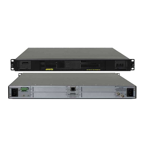
evertz 7800TR User manual

7700FR/7800FR MultiFrame
7800TR-32x24 Modular Tally Router
Revision 1.2 Page -i
TABLE OF CONTENTS
1OVERVIEW ...................................................................................................................................1
2SPECIFICATIONS.........................................................................................................................3
2.1 REAR GENERAL PURPOSE INPUTS .................................................................................3
2.2 REAR GENERAL PURPOSE OUTPUTS .............................................................................3
2.3 ETHERNET PORT................................................................................................................3
2.4 ELECTRICAL .......................................................................................................................3
2.5 PHYSICAL............................................................................................................................3
3INSTALLATION ............................................................................................................................5
3.1 REAR PANEL.......................................................................................................................5
3.2 ETHERNET CONNECTION..................................................................................................6
3.3 CARD EDGE ........................................................................................................................7
3.3.1 LED Indicators...........................................................................................................7
3.3.2 Card Edge Serial Port ...............................................................................................8
3.3.3 Frame Status LEDs ...................................................................................................9
3.3.4 LED Display...............................................................................................................9
3.4 REAR GENERAL PURPOSE INPUTS/OUTPUTS .............................................................11
3.5 GENERAL PURPOSE INPUTS ..........................................................................................13
3.6 GENERAL PURPOSE OUTPUTS ......................................................................................14
3.7 WET POWER .....................................................................................................................15
3.8 GENERAL PURPOSE I/O MODES ....................................................................................16
3.8.1 Tally Wet and Dry Terminology ...............................................................................16
3.8.2 General Purpose Output Modes ..............................................................................17
3.8.3 General Purpose Input Modes.................................................................................17
3.9 OPTIONAL 7800TR-BHP BULKHEAD PANEL..................................................................17
3.9.1 7800TR-BHP General Purpose Output Connections ...............................................18
3.9.2 7800TR-BHP General Purpose Input Connections..................................................19
4CONFIGURATION ......................................................................................................................20
4.1 SETTING THE IP ADDRESS..............................................................................................20
4.2 UPDATING AND USING VISTALINK PRO ........................................................................21
4.2.1 Updating VistaLINK® with a New JAR File..............................................................22
4.2.2 Applying a JAR update VistaLINK® Pro ..................................................................23
4.2.3 Opening the Configuration View for the 7800TR-32X24 in VistaLINK® Pro ............23
4.2.4 Opening the Alarm View for the 7800TR-32X24 in VistaLINK® Pro ........................24
4.3 CONFIGURING THE TALLY ROUTER ..............................................................................24
4.3.1 Selecting the Wet Voltage Source...........................................................................24
4.3.2 Configuring the GPI.................................................................................................25

7700FR/7800FR MultiFrame
7800TR-32x24 Modular Tally Router
Page -ii Revision 1.2
4.3.3 Configuring the GPO...............................................................................................25
5OPERATION ...............................................................................................................................26
5.1 QUARTZ REMOTE CONTROL PROTOCOL .....................................................................26
5.2 MAGNUM INTEGRATION..................................................................................................28
5.2.1 MAGNUM-TALLY License.......................................................................................28
5.2.2 Adding the Tally Router to MAGNUM......................................................................29
5.2.3 Setting up the MAGNUM Tally Grid.........................................................................30
6UPGRADING THE FIRMWARE ..................................................................................................31
6.1.1 Performing a Firmware Upgrade with VistaLINK® Pro ............................................31
6.1.2 Performing a Firmware Upgrade through the Card Edge Serial Port.......................32
Figures
Figure 1-1: 7800TR-32x24 with Accompanying Rear I/O Module (Rear plate) ................................................1
Figure 3-1: 7800TR-32x24 Rear Plate..............................................................................................................5
Figure 3-2: Card Edge LEDs and Serial Port....................................................................................................7
Figure 3-3: 7700 Upgrade Cable Picture (WA-S76) .........................................................................................8
Figure 3-4: Rear Plate 62-pin D-Sub Connectors Pinouts ..............................................................................11
Figure 3-5: Rear GPI Input Schematic............................................................................................................13
Figure 3-6: Rear General Purpose Output Circuit Diagram (Dry)...................................................................14
Figure 3-7: Optional 7800TR-BHP Bulkhead Panel........................................................................................18
Figure 3-8: 7800TR-BHP GPO in Wet Mode Circuit Diagram ........................................................................18
Figure 3-9: 7800TR-BHP GPO in Dry Mode Circuit Diagram .........................................................................19
Figure 3-10: 7800TR-BHP GPI in Wet Mode Circuit Diagram........................................................................19
Figure 3-11: 7800TR-BHP GPI in Dry Mode Circuit Diagram.........................................................................19
Figure 4-1: VistaLINK® Pro Version Information ............................................................................................22
Figure 4-2: VistaLINK® Pro Configuration View .............................................................................................23
Figure 4-3: VistaLINK Pro GPI Settings Tab...................................................................................................25
Figure 4-4: VistaLINK Pro GPO Settings Tab.................................................................................................26
Figure 5-1: Magnum License Management Screen........................................................................................28
Figure 5-2: Magnum Devices View .................................................................................................................29
Figure 5-3: Adding a Tally Router Device to Magnum ....................................................................................29
Figure 5-4: Magnum Tally Grid Configuration View ........................................................................................30
Figure 6-1: VistaLINK® Pro Upgrade Firmware Dialog ..................................................................................31
Tables
Table 3-1: Standard 8-pin Modular Connector Wiring Color Codes .................................................................6
Table 3-2: 7700 Upgrade Cable Wiring (WA-S76) ...........................................................................................8
Table 3-3: COM Port Settings...........................................................................................................................8
Table 3-4: Command Line Interface Commands..............................................................................................9
Table 3-5: Rear GPI Input Electrical Specifications ........................................................................................13
Table 3-6: Rear General Purpose Output Electrical Specifications ................................................................14
Table 3-7: Wet Power Source Selections .......................................................................................................15
Table 4-1: VistaLINK® Pro Configuration Tabs ..............................................................................................24

7700FR/7800FR MultiFrame
7800TR-32x24 Modular Tally Router
Revision 1.2 Page -iii
REVISION HISTORY
REVISION DESCRIPTION DATE
1.0 First release Sep 2016
1.1 Added notes, fixed GPI/GPO drawings. Firmware 1.00 b182 Dec 2016
1.2 Firmware 1.00 b182 Jan 2017
Information contained in this manual is believed to be accurate and reliable. However, Evertz assumes no responsibility for the use thereof
nor for the rights of third parties, which may be affected in any way by the use thereof. Any representations in this document concerning
performance of Evertz products are for informational use only and are not warranties of future performance, either expressed or implied. The
only warranty offered by Evertz in relation to this product is the Evertz standard limited warranty, stated in the sales contract or order
confirmation form.
Although every attempt has been made to accurately describe the features, installation and operation of this product in this manual, no
warranty is granted nor liability assumed in relation to any errors or omissions unless specifically undertaken in the Evertz sales contract or
order confirmation. Information contained in this manual is periodically updated and changes will be incorporated into subsequent editions. If
you encounter an error, please notify Evertz Customer Service department. Evertz reserves the right, without notice or liability, to make
changes in equipment design or specifications.

7700FR/7800FR MultiFrame
7800TR-32x24 Modular Tally Router
Page -iv Revision 1.2
This page left intentionally blank

7700FR/7800FR MultiFrame
7800TR-32x24 Modular Tally Router
Revision 1.2 Page -1
1 OVERVIEW
The 7800TR-32X24 is a Tally Router module that is housed in a 7700FR or 7800FR MultiFrame. It
provides an Ethernet-controlled interface for 32 General Purpose Outputs (GPOs) and 24 General
Purpose Inputs (GPIs). All General Purpose I/O (GPIO) are provided on two, 62-pin high density D-Sub
connectors on the rear plate. A gigabit 1000baseT Ethernet connection is used to configure and control
the unit.
The unit is configured with SNMP using the VistaLINK™ software. Advanced features such as edge
triggering on inputs, and variable-length pulse outputs are easily setup with the graphical user
interface. Each input or output can be set to normal logic (normally-open) or inverted logic (normally-
closed). In addition, the state of the inputs and outputs can be monitored or changed manually for
debugging purposes.
The Tally Router provides wet power on both of the rear 62-pin D-Sub connectors. This can be used to
power passive devices (tally lights, buttons, buzzers, etc) and to simplify wiring to GPIs and GPOs. The
wet power can be configured to come from either a 5V or 12V internal power source.
The MAGNUM control system with the MAGNUM-TALLY software module integrates the GPI and GPO
from the Tally Router into a single unified interface. The GPI and GPO of the Tally Router are
represented graphically as a virtual tally pin grid. Each GPI and GPO signal is given a source and
destination name. Custom triggers and behaviors can be easily setup to activate tally lights on
cameras, trigger Under Monitor Displays (UMDs), activate switchers, replay and record systems, and
more.
The 7800TR-32X24 occupies two slots in a 7700FR or 7800FR multiframe. The rear plate contains all
I/O connectors and is fixed to the rear of the frame. The 7800TR-32x24 module is hot-swappable from
the front of the frame. This means the module can be removed and re-inserted without disconnecting
the rear plate or any of the cabling.
Figure 1-1: 7800TR-32x24 with Accompanying Rear I/O Module (Rear plate)

7700FR/7800FR MultiFrame
7800TR-32x24 Modular Tally Router
Page -2Revision 1.2
Features & Benefits:
•32 General Purpose Outputs and 24 General Purpose Inputs on rear 62-pin D-Sub connectors.
•Wet power source selectable between internal 5V and 12V power sources.
•General Purpose Inputs are protected by optoisolators. Wide voltage range up to 24V.
•General Purpose Outputs are protected by polyfuses.
•Can configure General Purpose Inputs for edge, high, or low triggering.
•Can configure General Purpose Outputs as pulse or steady outputs.
•All General Purpose I/O can be setup as normal (normally-open) or inverted (normally-closed).
•Available 7800TR-BHP bulkhead panel to breakout rear GPIO.
•Gigabit Ethernet & Serial ports for SNMP configuration and Quartz Protocol control.

7700FR/7800FR MultiFrame
7800TR-32x24 Modular Tally Router
Revision 1.2 Page -3
2 SPECIFICATIONS
2.1 REAR GENERAL PURPOSE INPUTS
Number of GPIs: 24
Connectors: 2 x D-Subminiature DC-62 female sockets, each with 12 GPI
Maximum Voltage: +/- 24 Volts DC
Protection: Current limit, approximately 10mA – 15mA.
Wet Power: Provided on +WET and –WET pins (isolated from chassis ground)
Timing: GPI trigger to “.UV” Quartz protocol Ethernet packet transmission:
2ms – 30ms
2.2 REAR GENERAL PURPOSE OUTPUTS
Number of GPIs: 32
Connectors: 2 x D-Subminiature DC-62 female sockets, each with 16 GPO
Maximum Voltage: +/- 24 Volts DC
Protection: Polyfuse, 0.15 Amps maximum
Wet Power: Provided on +WET and –WET pins (isolated from chassis ground)
Timing: GPO relay closure upon receipt of “.SA” Quartz protocol command:
< 2ms
2.3 ETHERNET PORT
Network Type: Gigabit Ethernet 1000Base-T IEEE 802.3z
Connector: RJ-45
SNMP Standard: SNMP v1 compliant (RFC-1157, RFC-1213)
2.4 ELECTRICAL
Voltage: + 12V DC
Power Consumption
Wet Power Off: 10 watts typical (Wet power not being used)
Wet Power On: 50 watts max (internal 5V or 12V power being used)
EMI/RFI:Complies with FCC regulations for class A devices.
Complies with EU EMC directive.
2.5 PHYSICAL
Number of Slots: 2
Enclosures:
7700FR-C: 200W 3RU Multiframe – holds up to 15 single slot modules.
7800FR(-QT): 360W 3RU Multiframe with genlock – holds up to 15 single slot modules.
350FR: 160W 3RU Portable Multiframe – holds up to 7 single slot modules.
7801FR: 100W 1RU Multiframe – holds up to 4 single slot modules.
Operating Temperature: 0ºC to +40ºC (32ºF to 104ºF) ambient

7700FR/7800FR MultiFrame
7800TR-32x24 Modular Tally Router
Page -4Revision 1.2
This page left intentionally blank

7700FR/7800FR MultiFrame
7800TR-32x24 Modular Tally Router
Revision 1.2 Page -5
3 INSTALLATION
3.1 REAR PANEL
Figure 3-1 is an illustration of the rear plate I/O module that accompanies the 7800TR-32x24. The rear
plate occupies two slots in a 7700FR multiframe. There are two female high-density 62-pin D-Sub
connectors for the 32 general purpose outputs, 24 general purpose inputs, and wet voltage. There is
also a gigabit Ethernet jack for configuration and control. Install the rear plate onto the rear of the
multiframe in a free location of your choice. Secure the rear plate using the four provided M2.5 x 8mm
screws. Take note of the two slot numbers the rear plate occupies.
Figure 3-1: 7800TR-32x24 Rear Plate
A ribbon cable joins the two boards inside the rear plate. When installing the rear
plate into a frame, take care that this ribbon cable does not become dislodged at
either end or pinched against the frame metal.

7700FR/7800FR MultiFrame
7800TR-32x24 Modular Tally Router
Page -6Revision 1.2
3.2 ETHERNET CONNECTION
The 7800TR-32x24 is equipped with a Gigabit Ethernet port. It can be used with either 100base-TX
(100 Mbps) or 1000base-T (1 Gbps) twisted pair Ethernet networks. Category 5e UTP cable or better
is required with a maximum length of less than 100 meters (328 feet). The cable must be “straight
through” with an 8-pin modular connector at each end. Make the network connection by plugging one
end of the cable into the tally router and the other end into an Ethernet hub or switch.
The straight-through Ethernet cable can be purchased or can be constructed using the pinout
information in Table 3-1. A color code wiring chart is provided in Table 3-1 for the current Ethernet
standards (AT&T 258A or EIA/TIA 258B color coding shown). Also refer to the notes following the table
for additional wiring guide information.
1 2 3 4 5 6 7 8
Pin# EIA/TIA 568A
AT&T 258A or
EIA/TIA 568B
100Base-TX 1000Base-T
1
White/Green stripe
White/Orange stripe
Transmit +
TxRx A+
2 Green Orange Transmit –
TxRx A-
3 White/Orange stripe White/Green stripe Receive +
TxRx B+
4 Blue Blue Not Used (required)
TxRx C+
5 White/Blue stripe White/Blue stripe Not Used (required)
TxRx C-
6 Orange Green Receive –
TxRx B-
7
White/Brown stripe
White/Brown stripe
Not Used (required)
TxRx D+
8
Brown
Brown
Not Used (required)
TxRx D-
Table 3-1: Standard 8-pin Modular Connector Wiring Color Codes
The gigabit Ethernet port has two green LEDs marked “LNK” and “ACT”. The “LNK” LED will illuminate
green when the connection speed is 1000base-T and will be off for 100base-T. The “ACT” LED will
blink green with Ethernet activity. The Ethernet standard mandates auto-negotiation so crossover
cables are no longer required. The initial TCP/IP settings of the unit can be set through the
configuration serial port.
The current firmware (v1.00 b182) does not support 10baseT link speeds.
The link may come up, but no data will be transmitted.

7700FR/7800FR MultiFrame
7800TR-32x24 Modular Tally Router
Revision 1.2 Page -7
3.3 CARD EDGE
The front card edge of the module can be accessed by opening the frame door. There are several
diagnostic LEDs and a card edge serial port connection. This serial port is used to set the initial
configuration of the card and can also be used for debugging.
7800TR-
32x24
Frame Status LEDs
LED Display
J8 - Serial Port
LD6 - Ethernet
LD7 – Power Good
LD10 – FPGA Done
LD5 – Always Off
LD4 – Always Off
LD3 – Always Off
LD2 – Always Off
Figure 3-2: Card Edge LEDs and Serial Port
3.3.1 LED Indicators
Most of the small LED indicators are currently reserved for factory use.
LD7 indicates the power status of the card. This LED should always be illuminated Green. If it is off,
this indicates a problem with the power supply of the card.
LD10 should always be off during normal operation. If this LED is Red, this indicates that the card is
not booting properly.
LD6 will illuminate Green where there is no Ethernet link. It should be off under normal operation.

7700FR/7800FR MultiFrame
7800TR-32x24 Modular Tally Router
Page -8Revision 1.2
3.3.2 Card Edge Serial Port
The 4-pin header at the card edge (J8) contains a serial port that must be used to set the IP address of
the card. This requires an Evertz WA-S76 rainbow cable, also known as a 7700 Upgrade Cable. This
cable is shipped with every Multiframe and is common to all 7700/7800 modular cards.
Figure 3-3: 7700 Upgrade Cable Picture (WA-S76)
7800TR-32x24 (J8) End
6 Conductor
Ribbon
PC End (RS-232)
2 row x 3 pin Berg
Pin
9 pin D-Sub Female
Pin
Reserved
1
Brown
---
-
KEY
2
Red
---
-
Ground
3
Orange
Ground
5
Rx
4
Yellow
Tx
3
Tx
5
Green
Rx
2
KEY
6
Blue
---
-
Table 3-2: 7700 Upgrade Cable Wiring (WA-S76)
Connect the rectangular 3x2 pin connector of the WA-S76 cable to the card edge connector J8. The
connector is keyed so that it will only go on one way. Connect the 9-pin female D-Sub connector to a
COM port on a laptop or PC. You will need to start a terminal program such as Hyperterminal or
Teraterm, and open the respective COM port. Configure the COM port settings as follows:
Baud
115200
Data Bits
8
Parity
None
Stop Bits
2
Flow Control
None
Table 3-3: COM Port Settings

7700FR/7800FR MultiFrame
7800TR-32x24 Modular Tally Router
Revision 1.2 Page -9
The card edge serial port is used for configuration, debug, and for upgrading the firmware on the card.
Press ENTER in the terminal program and a “CLI>” prompt will be displayed. It is not recommended to
play around with the command line interface unless under direction of Evertz customer support. The
following commands may be used to configure, upgrade, or find information about the unit:
Command
Description
ver
Will display hardware and software version of the tally router
ifconfig
Used to configure the TCP/IP settings for the Ethernet port. Enter on one line:
ifconfig 0 inet [IP] netmask [SUBNETMASK] broadcast [BROADCAST]
gateway [GATEWAY]
reset
Will reboot the unit (in order to perform a serial software upgrade)
Table 3-4: Command Line Interface Commands
3.3.3 Frame Status LEDs
These two LEDs indicate the overall health of the card. During normal operation the Green LED will be
on, and the Red LED will be off. If the Green LED is off or the Red LED is on, this indicates a problem
with the card. This fault condition can trigger the global frame status if jumper J15 is placed in the
FAULT position. This will cause the Frame Status LEDs on the power supply of the frame to turn Red,
and will also cause the GROC connection on the back of the frame to go into the fault position. A
triggered frame status can also be detected by the frame controller, if one is installed in the frame.
3.3.4 LED Display
The dot matrix LED display is used to display the product name (7800TR-32x24), and also the current
firmware version and build, as well as the currently configured IP address. These three pieces of
information will scroll alternately across the display.

7700FR/7800FR MultiFrame
7800TR-32x24 Modular Tally Router
Page -10 Revision 1.2
This page left intentionally blank

7700FR/7800FR MultiFrame
7800TR-32x24 Modular Tally Router
Revision 1.2 Page -11
3.4 REAR GENERAL PURPOSE INPUTS/OUTPUTS
There are two 62-pin Female D-Sub connectors on the rear plate of the unit. These contain the 32
General Purpose Outputs (GPOs) and 24 General Purpose Inputs (GPIs). There are also power pins
for wet voltage and ground. The pinouts are shown below in Figure 3-4. Each unit ships with two 62-pin
male D-Sub connectors (Assmann A-HDS 62 LL/Z) and backshells (FCI 8655MH3701BLF) to allow
creation of custom cables.
21 20 19 18 1617 15 1314 12 11 10 9 8 7 6 5 43 2 1
42 41 40 39 37
38 36 3435 33 32 31 30 29 28 27 26 25 24 23 22
62 61 60 59 5758 56 5455 53 52 51 50 49 48 47 46 45 44 43
OUTPUTS (17-32) / INPUTS (13-24)
21 20 19 18 16
17 15 13
14 12 11 10 9 8765 4 321
42 41 40 39 3738 36 3435 33 32 31 30 29 28 27 26 25 24 23 22
62 61 60 59 57
58 56 5455 53 52 51 50 49 48 47 46 45 44 43
OUTPUTS (1-16) / INPUTS (1-12)
GPI
1+
GPI
1-
GPI
4+
GPI
4-
GPI
7-
GPI
7+
GPI
10+
GPO
1A
GPI
10-
GPO
1B
GPO
4A
GPO
4B
GPO
7A
GPO
7B
GPO
10A
GPO
10B
GPO
13A
GPO
13B
GPO
16A GND WET+
GPI
2+
GPI
2-
GPI
5+
GPI
5-
GPI
8-
GPI
8+
GPI
11+
GPO
2A
GPI
11-
GPO
2B
GPO
5A
GPO
5B
GPO
8A
GPO
8B
GPO
11A
GPO
11B
GPO
14A
GPO
14B
GPO
16B GND WET+
GPI
3+
GPI
3-
GPI
6+
GPI
6-
GPI
9-
GPI
9+
GPI
12+
GPO
3A
GPI
12-
GPO
3B
GPO
6A
GPO
6B
GPO
9A
GPO
9B
GPO
12A
GPO
12B
GPO
15A
GPO
15B GND WET+
21 20 19 18 17 16 15 14 9 8 7 6 5 4 3 213 12 11 10 1
42 41 40 39 38 37 36 35 30 29 28 27 26 25 24 2334 33 32 31 22
62 61 60 59 58 57 56 55 50 49 48 47 46 45 44 4354 53 52 51
GPI
13+
GPI
13-
GPI
16+
GPI
16-
GPI
19-
GPI
19+
GPI
22+
GPO
17A
GPI
22-
GPO
17B
GPO
20A
GPO
20B
GPO
23A
GPO
23B
GPO
26A
GPO
26B
GPO
29A
GPO
29B
GPO
32A GND WET+
GPI
14+
GPI
14-
GPI
17+
GPI
17-
GPI
20-
GPI
20+
GPI
23+
GPO
18A
GPI
23-
GPO
18B
GPO
21A
GPO
21B
GPO
24A
GPO
24B
GPO
27A
GPO
27B
GPO
30A
GPO
30B
GPO
32B GND WET+
GPI
15+
GPI
15-
GPI
18+
GPI
18-
GPI
21-
GPI
21+
GPI
24+
GPO
19A
GPI
24-
GPO
19B
GPO
22A
GPO
22B
GPO
25A
GPO
25B
GPO
28A
GPO
28B
GPO
31A
GPO
31B GND WET+
21 20 19 18 17 16 15 14 9 8 7 6 5 4 3 213 12 11 10 1
42 41 40 39 38 37 36 35 30 29 28 27 26 25 24 2334 33 32 31 22
62 61 60 59 58 57 56 55 50 49 48 47 46 45 44 4354 53 52 51
Figure 3-4: Rear Plate 62-pin D-Sub Connectors Pinouts

7700FR/7800FR MultiFrame
7800TR-32x24 Modular Tally Router
Page -12 Revision 1.2
OUTPUTS (17-32) / INPUTS (13-24)
OUTPUTS (1-16) / INPUTS (1-12)
GPI
1+
GPI
1-
GPI
4+
GPI
4-
GPI
7-
GPI
7+
GPI
10+
GPO
1A
GPI
10-
GPO
1B
GPO
4A
GPO
4B
GPO
7A
GPO
7B
GPO
10A
GPO
10B
GPO
13A
GPO
13B
GPO
16A GND WET+
GPI
2+
GPI
2-
GPI
5+
GPI
5-
GPI
8-
GPI
8+
GPI
11+
GPO
2A
GPI
11-
GPO
2B
GPO
5A
GPO
5B
GPO
8A
GPO
8B
GPO
11A
GPO
11B
GPO
14A
GPO
14B
GPO
16B GND WET+
GPI
3+
GPI
3-
GPI
6+
GPI
6-
GPI
9-
GPI
9+
GPI
12+
GPO
3A
GPI
12-
GPO
3B
GPO
6A
GPO
6B
GPO
9A
GPO
9B
GPO
12A
GPO
12B
GPO
15A
GPO
15B GND WET+
21 20 19 18 17 16 15 14 9 8 7 6 5 4 3 213 12 11 10 1
42 41 40 39 38 37 36 35 30 29 28 27 26 25 24 2334 33 32 31 22
62 61 60 59 58 57 56 55 50 49 48 47 46 45 44 4354 53 52 51
GPI
13+
GPI
13-
GPI
16+
GPI
16-
GPI
19-
GPI
19+
GPI
22+
GPO
17A
GPI
22-
GPO
17B
GPO
20A
GPO
20B
GPO
23A
GPO
23B
GPO
26A
GPO
26B
GPO
29A
GPO
29B
GPO
32A GND WET+
GPI
14+
GPI
14-
GPI
17+
GPI
17-
GPI
20-
GPI
20+
GPI
23+
GPO
18A
GPI
23-
GPO
18B
GPO
21A
GPO
21B
GPO
24A
GPO
24B
GPO
27A
GPO
27B
GPO
30A
GPO
30B
GPO
32B GND WET+
GPI
15+
GPI
15-
GPI
18+
GPI
18-
GPI
21-
GPI
21+
GPI
24+
GPO
19A
GPI
24-
GPO
19B
GPO
22A
GPO
22B
GPO
25A
GPO
25B
GPO
28A
GPO
28B
GPO
31A
GPO
31B GND WET+
21 20 19 18 17 16 15 14 9 8 7 6 5 4 3 213 12 11 10 1
42 41 40 39 38 37 36 35 30 29 28 27 26 25 24 2334 33 32 31 22
62 61 60 59 58 57 56 55 50 49 48 47 46 45 44 4354 53 52 51

7700FR/7800FR MultiFrame
7800TR-32x24 Modular Tally Router
Revision 1.2 Page -13
3.5 GENERAL PURPOSE INPUTS
There are 24 General Purpose Inputs (GPIs) available on the two 62-pin D-Sub connectors on the rear
plate. The GPIs are “wet” meaning they need external voltage to function. The GPI ports are used to
read the tallies (GPOs) from products such as a vision mixer (production switcher). The pinout of these
connectors is shown in Figure 3-4.
Note that the GPI inputs are polarity sensitive. The circuit diagram is shown in Figure 3-5 and the
electrical specifications are in Table 3-5 and also in Section 2.1. The GPI input is protected by a
current source which limits the current into an optoisolator. The optoisolator is used to protect the tally
router’s internal circuitry, and also to isolate the GPIs from each other. If more than +/- 24 volts is
applied to a GPI it may become damaged but the damage will be isolated to the particular GPI.
The selected Wet Power source is available on three pins of each D-Sub connector as WET+ and
GND. This wet power can be used to wire the GPIs as “Dry”. Please see Section 3.8 for more
information on the wiring and the Wet/Dry terminology.
GPI +
GPI -
~10 mA
~1.4 V
optoisolator
Figure 3-5: Rear GPI Input Schematic
Maximum GPI Voltage
+24 Volts DC
Maximum Reverse GPI Voltage
-24 Volts DC
Voltage to Turn GPI On
> +2.0 Volts
Voltage to Turn GPI Off
< +1.0 Volts
GPI Current Limiting
~10mA @ +5V
~12mA @ +12V
~15mA @ +24V
Table 3-5: Rear GPI Input Electrical Specifications
Do not apply a voltage higher or lower than the maximums or the
GPI may be
permanently damaged.

7700FR/7800FR MultiFrame
7800TR-32x24 Modular Tally Router
Page - 14 Revision 1.2
3.6 GENERAL PURPOSE OUTPUTS
There are 32 General Purpose Outputs (GPOs) available on the two 62-pin D-Sub connectors on the
rear plate. The rear GPOs are “Dry”. The GPOs can be used to activate tally lights or send triggers to
equipment such as the Evertz VIP multiviewers, switchers, and keyers. They can also be used to drive
camera tally lamps. The pinout of these connectors is shown in Figure 3-4.
The General Purpose Outputs are not polarity sensitive. Each GPO has two pins marked “A” and “B”.
The GPO consists of an isolated relay contact. When the GPO is closed, the two contacts “A” and “B”
will be electrically connected to each other. See Figure 3-6 for the circuit diagram of a GPO. The GPO
specifications are listed in section 2.2.
Each GPO is protected against excessive current with a polyfuse. Polyfuses operate by means of
thermal limiting. The maximum allowable current is shown in Table 3-6. If excessive current is applied
to the GPO the polyfuse will heat up and open. This process happens very quickly if the current is high
but may take hours if the current is only a little above the maximum. When the polyfuse opens, it
immediately begins to cool and will eventually reset on its own. If the fault is not removed, the process
will repeat itself any may cause a “strobing” effect on some load devices connected to the GPO.
The currently selected Wet Power source is available on three pins of the D-Sub connector. The WET+
voltage can be used to wire the GPOs as “Wet”. Please see section 0 for more information.
GPO A
GPO B
0.15A max Relay
Figure 3-6: Rear General Purpose Output Circuit Diagram (Dry)
Maximum Current
0.15 Amps
Maximum Voltage
+/- 24V DC
Closed Contact Resistance
< 3.0 Ω
Table 3-6: Rear General Purpose Output Electrical Specifications
Do not exceed the maximum voltage specified or the GPO may be damaged.

7700FR/7800FR MultiFrame
7800TR-32x24 Modular Tally Router
Revision 1.2 Page -15
3.7 WET POWER
The 7800TR-32X24 has wet power sources that are available on the two D-Sub connectors on the rear
plate. They can be used to provide voltage to GPIs and GPOs. This allows the GPIO to be either
powered or unpowered depending on the requirements of the equipment that needs to be interfaced to
(see section 0). This wet power source is available on the WET+and GND pins.
The tally router’s wet power is software-selectable between two sources:
Wet Power Source
Description
+5V
The internal +5V power will be connected to WET+. The GND pins act as the
return (chassis ground).
+12V
The internal +12V power will be connected to WET+. The GND pins act as
the return (chassis ground).
Table 3-7: Wet Power Source Selections
The wet power source WET+is protected by a 1.5 Amp polyfuse, no matter which voltage source is
selected. Care must be taken to limit the cumulative WET+current draw out of the rear D-Sub
connectors to 1.5 Amps or less.
If more current than the maximum is drawn, to the WET voltage polyfuse will heat up and open. This
process happens very quickly if the current is high, but could take hours if the current is only a little
above the maximum. When the fault is removed the polyfuse will begin to cool and will eventually reset
on its own. Note that with some types of faults this heating/cooling (fault/reset) process can happen
repeatedly, causing a “strobing” effect on the WET power to the load.
After changing the wet power source, allow 30 seconds for the setting to save
before rebooting or removing power from the card.

7700FR/7800FR MultiFrame
7800TR-32x24 Modular Tally Router
Page - 16 Revision 1.2
3.8 GENERAL PURPOSE I/O MODES
The 7800TR-32X24 tally router is designed to have flexible General Purpose I/O to allow them to be
used for a wide range of purposes such as illuminating lamps, and reading the state of switches. The
GPIs and GPOs can be hard-wired in Wet or Dry mode to interface with both powered and unpowered
devices using the provided WET voltage pins. The GPIs have a wide voltage range and high sensitivity
(see Table 3-5). The GPO relay contacts can support a relatively high current flow (see Table 3-6).
3.8.1 Tally Wet and Dry Terminology
The Tally Router is named after the most common use which is driving tally lights on cameras. In a live
recording studio with multiple cameras, each camera has a tally light which indicates it is the one that is
currently being broadcast. The director sends commands to switch between the cameras. The main
video router switches the video feed between the cameras, and the tally router follows by switching the
corresponding tally light GPOs.
Throughout this manual the “wet” and “dry” terminology is used to describe whether a GPO and GPI
provides/requires an external voltage source to operate. This terminology is arcane and confusing
outside its narrow scope of usage. The term “Wet” means that voltage is present and “Dry” means no
voltage, always from the perspective of the output port (General Purpose Output).
When connecting a GPO to a GPI, remember “Wet” to “Wet” and “Dry” to “Dry”.
Never connect “Wet” to “Dry” or vice-versa.
A General Purpose Output has two contacts marked “A” and “B”. A “Dry” GPO opens these two
contacts when OFF, and closes them when turned ON. No voltage is supplied. A “Wet” GPO provides
+WET voltage when it is activated in order to provide power to a downstream device such as a light
bulb, buzzer, or Wet GPI. See section 3.6 for more information.
A “Wet” GPO provides voltage to the downstream device.
A “Dry” GPO does not provide voltage to the downstream device.
The General Purpose Inputs are used to read the state of another device. This may be a passive
device such as a pushbutton or switch, but is often connected to a GPO. A “Wet” GPI is named such
that it is wired to connect to a “Wet” GPO. This means a “Wet” GPI does not provide its own voltage
source. A “Dry” GPI is meant to interface to a “Dry” GPO. This means that it provides a +WET voltage
which the external device must return in order to activate the GPI. See section 3.5 for more
information.
A “Wet” GPI requires an external voltage to be applied in order to activate it.
A “Dry” GPI requires only an external contact closure to return its own voltage to activate it
Table of contents
Other evertz Controllers manuals