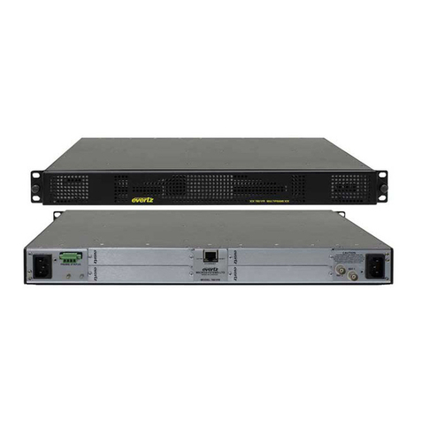
evertz 7700 Series User manual

7700 MultiFrame Manual
7700SRV-XRF System Controller
Revision 1.2
TABLE OF CONTENTS
1. OVERVIEW.......................................................................................................................................... 1
1.1. INTRODUCTION......................................................................................................................... 1
1.2. SYSTEM DIAGRAM................................................................................................................... 1
2. INSTALLATION................................................................................................................................... 3
2.1. FRAME ....................................................................................................................................... 3
2.2. BACKPANEL CONNECTIONS.................................................................................................. 3
2.2.1. Serial Control Port Connections............................................................................................ 3
2.2.2. Ethernet Connections............................................................................................................4
3. STATUS INDICATORS AND DISPLAY.............................................................................................. 5
3.1. CARD EDGE............................................................................................................................... 5
4. CONFIGURATION............................................................................................................................... 7
4.1. CONFIGURATION VIA CARD EDGE SERIAL CONNECTION................................................. 7
4.1.1. Network Configuration...........................................................................................................8
4.1.2. Serial Control Port Settings................................................................................................... 9
4.1.3. SNMP Settings...................................................................................................................... 9
4.1.4. Other Settings ..................................................................................................................... 10
4.1.5. Upgrading Firmware via Serial Connection......................................................................... 10
4.2. MATRIX CONFIGURATION USING SNMP ............................................................................. 10
4.2.1. Example 128x128 Configuration ......................................................................................... 11
5. X-NCP2 PANEL OPERATION ..........................................................................................................13
5.1. X-NCP2 CONTROL PANEL..................................................................................................... 13
5.1.1. Example 1: Pushbutton Control to Switch Input 2 to Output 5 ........................................... 14
5.1.2. Example 2: Rotary Knob Control to Switch Input 2 to Output 5 ......................................... 14
5.1.3. Example 3: Setting the Gain to +6dB in Manual Model on All Inputs................................. 15
5.1.4. Example 4: Executing a Salvo Command.......................................................................... 15

7700 MultiFrame Manual
7700SRV-XRF System Controller
Revision 1.2
Figures
Figure 1-1: Connection Diagram for System Controller with XRF6 Routers for a 128x128 System ................... 1
Figure 2-1: Rear Panel of 7700SRV-XRF ............................................................................................................. 3
Figure 3-1: 7700SRV-XRF card edge................................................................................................................... 5
Figure 4-1: Upgrade Cable and PCB Connector for Serial Connection. ..............................................................7
Figure 4-2: Connection Diagram for 128x128 Matrix Using Four XRF6-64x64 Routers .................................... 11
Tables
Table 2-1: SCP RS232 Pinout .............................................................................................................................. 3
Table 2-2: SCP RS422 Pinout .............................................................................................................................. 4
Table 4-1: Chassis Orientation Table.................................................................................................................. 12

7700 MultiFrame Manual
SRV-XRF System Controller
Revision 1.2
REVISION HISTORY
REVISION DESCRIPTION DATE
0.0 Preliminary Release Jul 06
1.1 Updates/corrections Aug 06
1.2 General format cleanup Sept 09
Information contained in this manual is believed to be accurate and reliable. However, Evertz assumes no responsibility for the use thereof nor for
the rights of third parties, which may be affected in any way by the use thereof. Any representations in this document concerning performance of
Evertz products are for informational use only and are not warranties of future performance, either expressed or implied. The only warranty offered
by Evertz in relation to this product is the Evertz standard limited warranty, stated in the sales contract or order confirmation form.
Although every attempt has been made to accurately describe the features, installation and operation of this product in this manual, no warranty is
granted nor liability assumed in relation to any errors or omissions unless specifically undertaken in the Evertz sales contract or order confirmation.
Information contained in this manual is periodically updated and changes will be incorporated into subsequent editions. If you encounter an error,
please notify Evertz Customer Service department. Evertz reserves the right, without notice or liability, to make changes in equipment design or
specifications.

7700 MultiFrame Manual
SRV-XRF System Controller
Revision 1.2
This page left intentionally blank

7700 MultiFrame Manual
SRV-XRF System Controller
Revision 1.2 Page - 1
1. OVERVIEW
1.1. INTRODUCTION
The 7700SRV-XRF is the system controller (SC) for multi frame L band matrices comprised of Evertz
Microsystems L band routers. A maximum matrix size of 512x512 is achievable with the XRF6 router.
The 7700SRV-XRF hardware consists of a maximum of two SC cards housed in a 1RU 7701 multiframe
with optional dual power supply. One card is designated the primary SC card and the other the
secondary SC card. The secondary is optional and provides redundancy. At any given time, one SC
card is deemed active. Only the active SC card initializes the individual XRF6 routers. If present, the
other SC card is deemed standby. Both SC cards monitor their communication paths to the XRF6
routers. By default, when the system controller is powered on, the primary SC card becomes active and
the secondary SC card becomes standby. Switchover between the active and standby system controller
cards is automatic and the conditions causing switchover are discussed in section 1.2.
1.2. SYSTEM DIAGRAM
Figure 1-1 illustrates the connection configuration for an XRF system controller.
VLPro / SNMP
Management
Software
Primary
System
Controller
Secondary
System
Controller
Primary Primary Primary Primary
Secondary Secondary Secondary Secondary
X-NCP2
#1
X-NCP2
#8
ETHERNET
FC FC
7700SRV-XRF
Chassis
X6RF-PS
FRAME
STATU S
PSU
STATUS
ON OFF
POWER SUPPL Y
XRF6-F C
XRF6-I16LB
XRF6-
O16LB64x64
XRF6-I16LB
XRF6-I16LB
XRF6-I16LB
XRF6-
O16LB64x64
XRF6-
O16LB64x64
XRF6-
O16LB64x64
XRF6-FC
X6RF-PS
FRAME
STATUS
PSU
STAT US
ON OFF
POWERSUPPLY
Power
Supply A
Power
SupplyB
Frame
Controller B
Frame
Controller A
SLOT 1 SLOT 2 SLOT 3 S LOT 4 SLOT 5 SLOT 6 SLOT 7 SLOT 8
INPUTS
1- 16 INPUTS
17 -32 INPUTS
33-48 INPUTS
49-64
OUTPUTS
17-32
OUTP UTS
1-16 OUTPUTS
33-48 OUTPUTS
49-64
X6RF-PS
FRAME
STAT US
PSU
STATUS
ON OFF
POWER SUPPLY
XRF6-F C
XRF6-I16LB
XRF6-
O16LB64x64
XRF6-I16LB
XRF6-I16LB
XRF6-I16LB
XRF6-
O16LB64x64
XRF6-
O16LB64x64
XRF6-
O16LB64x64
XRF6-FC
X6RF-PS
FRAME
STATUS
PSU
STATUS
ON OFF
POWERSUPPLY
Power
SupplyA
Power
SupplyB
Frame
Controller B
Frame
Controller A
SLOT 1 SLO T 2 SLOT 3 SLOT 4 SLOT 5 SLOT 6 S LOT 7 SLOT 8
INPUTS
1-16 INPUTS
17- 32 INPUTS
33-48 INPUTS
49-64
OUTPUTS
17- 32
OUTPUTS
1-16 OUTPUTS
33-48 OUTPUTS
49-64
X6RF-PS
FRAME
STATU S
PSU
STATUS
ON OFF
POWER SUPPL Y
XRF6-F C
XRF6-I16LB
XRF6-
O16LB64x64
XRF6-I16LB
XRF6-I16LB
XRF6-I16LB
XRF6-
O16LB64x64
XRF6-
O16LB64x64
XRF6-
O16LB64x64
XRF6-FC
X6RF-PS
FRAME
STATUS
PSU
STAT US
ON OFF
POWERSUPPLY
Power
Supply A
Power
SupplyB
Frame
Controller B
Frame
Controller A
SLOT 1 SLOT 2 SLOT 3 S LOT 4 SLOT 5 SLOT 6 SLOT 7 SLOT 8
INPUTS
1- 16 INPUTS
17 -32 INPUTS
33-48 INPUTS
49-64
OUTPUTS
17-32
OUTP UTS
1-16 OUTPUTS
33-48 OUTPUTS
49-64
X6RF-PS
FRAME
STAT US
PSU
STATUS
ON OFF
POWE R SU P PLY
XRF6-FC
XRF6-I16LB
XRF6-
O16LB64x64
XRF6-I16LB
XRF6-I16LB
XRF6-I16LB
XRF6-
O16LB64x64
XRF6-
O16LB64x64
XRF6-
O16LB64x64
XRF6-FC
X6RF-PS
FRAME
STATUS
PSU
STATUS
ON OFF
POWER SUPPL Y
Power
Supply A
Power
SupplyB
Fram e
Controller B
Frame
Controller A
SLOT 1 SLOT 2 SLOT 3 SLOT 4 SLOT 5 SLOT 6 SLOT 7 SLOT 8
INPUTS
1-16 INPUTS
17-32 INPUTS
33- 48 INPUTS
49-64
OUTPUTS
17-32
OUTPUTS
1-16 OUTPUTS
33-48 OUTPUTS
49-64
Figure 1-1: Connection Diagram for System Controller with
XRF6 Routers for a 128x128 System
Four XRF6 routers are illustrated for a 128x128 configuration (RF splitters and combiners not shown).
Each XRF6 router has two frame controller (FC) cards that are designated as either primary or
secondary via the chassis orientation table of the SC.
It is strongly recommended that all equipment involved with the router system be located on its own IP
network.

7700 MultiFrame Manual
SRV-XRF System Controller
Page - 2 Revision 1.2
The SC uses SNMP (Simple Network Management Protocol) to communicate with the FCs of each
router. The primary SC card communicates with the primary FCs and the secondary SC card
communicates with the secondary FCs.
Control of the router system can be accomplished by using any combination of SNMP manager software
(such as VL-Pro), X-NCP2 panels, or Evertz Router Control (ERC) protocol over the SC’s Serial Control
Port (SCP). The control system(s) must interface with the active SC card.
Automatic switchover from the active SC to standby occurs under the following situations:
•The active SC fails to communicate with one of its router FC cards.
•The active SC is removed from its chassis.
•The active SC fails to provide a watchdog handshake response to the standby SC.
Manual changeover can be forced using:
•SNMP (VL-Pro)
•A serial console connected to the upgrade port of one of the SC cards.
For any switchover to take place:
•The standby SC must be present within the chassis.
•The standby SC must provide a watchdog handshake response to the active SC.
•The standby SC must be able to communicate with all of its router FC cards.
Up to 8 X-NCP2 network control panels can be connected to the active SC card. If switchover occurs
between the SC cards, the operator must have the X-NCP2 panel initiate a communications session with
the new active SC card.

7700 MultiFrame Manual
SRV-XRF System Controller
Revision 1.2 Page - 3
2. INSTALLATION
The 7700SRV-XRF comes with a 1RU 7701 Evertz Microsystems Multiframe with rear panel. There are
three slots available on this chassis. The second and third slots from the left (facing the front of the
frame) are used for the 7700SRV-XRF cards.
2.1. FRAME
The 7701 Evertz Microsystems multiframe has a door at the front which can be opened by loosening the
two screws at the far sides of the door.
2.2. BACKPANEL CONNECTIONS
The rear panel of the 7700SRV-XRF is illustrated in Figure 2-1.
Figure 2-1: Rear Panel of 7700SRV-XRF
There are serial and ethernet connections for both the primary and secondary cards. The pinout for the
12 pin strip connector is illustrated on the back panel. There are two ports available on each connector
and are labelled (1) and (2).
2.2.1. Serial Control Port Connections
Table 2-1 illustrates the pinout for the serial control port (SCP) when operating in RS232 mode.
Pin Number Signal
1 TX (1)
3 RX (1)
5 GND
7 TX (2)
9 RX (2)
11 GND
Table 2-1: SCP RS232 Pinout

7700 MultiFrame Manual
SRV-XRF System Controller
Page - 4 Revision 1.2
Table 2-2 illustrates the pinout for the SCP when operating in RS422 mode.
Pin Number Signal
1 TX- (1)
2 TX+ (1)
3 RX- (1)
4 RX+ (1)
5 GND
6 GND
7 TX- (2)
8 TX+ (2)
9 RX- (2)
10 RX+ (2)
11 GND
12 GND
Table 2-2: SCP RS422 Pinout
2.2.2. Ethernet Connections
There are two ethernet connections on the rear panel of the 7700SRV-XRF. One connection is for the
primary SC card and the other for the secondary SC card. Use a ‘straight-thru’ network cable to connect
this device to an Ethernet switch.
It is strongly recommended that all equipment involved with the router system be located on its own IP
network.

7700 MultiFrame Manual
SRV-XRF System Controller
Revision 1.2 Page - 5
3. STATUS INDICATORS AND DISPLAY
The 7700SRV-XRF includes a number of status LEDs, a toggle switch and 4 character dot matrix display
for monitoring and diagnostics. The large green and red LEDs next to the toggle switch are used to
indicate the overall health of the card. The three small LEDs on the card edge illustrated in Figure 3-1
indicate the current operating mode of the card and information on the peer card in the frame.
3.1. CARD EDGE
Red Gr
Toggle
X R F S
LED 1 LED 2 LED 3
Figure 3-1: 7700SRV-XRF card edge
LED Off On
1 SC is in secondary slot. SC is in primary slot.
2 SC does not detect its
peer physically within the
chassis.
SC detects its peer
physically within the
chassis.
3 SC is active. SC is standby.

7700 MultiFrame Manual
SRV-XRF System Controller
Page - 6 Revision 1.2
Status LED: The large green and red LEDs at the top of the board indicate the card status. Only
one of these LEDs will be on at any time after power up. The Red LED ON indicates
an error has occurred and has been logged in the event log. Reading the event log
returns the status LED to green. The green LED ON indicates the system controller is
operating normally.
Toggle Switch: The toggle switch is used to display either the active / standby status of the SC card or
the IP address of the SC card. Moving the switch to the left will display ACTIVE or
STANDBY on the dot matrix display to indicate the current operating status of the card.
Moving the switch to the right will display the IP address of the card on the dot matrix
display.

7700 MultiFrame Manual
SRV-XRF System Controller
Revision 1.2 Page - 7
4. CONFIGURATION
The serial port console of the SC can be used to configure the network settings, serial port control
settings and SNMP settings of the card.
4.1. CONFIGURATION VIA CARD EDGE SERIAL CONNECTION
The basic steps in configuring the 7700SRV-XRF are:
"Note: The following steps are to be repeated on any secondary SC card.
1. Connect a PC serial cable to the 4 pin 7700SRV-XRF connector J1 using the Evertz
Microsystems upgrade cable ( female DB9 serial connector to 2x3 strip connector ) as illustrated
in Figure 4-1.
Figure 4-1: Upgrade Cable and PCB Connector for Serial Connection.
2. Open a HyperTerminal session with settings baud rate=115200bps, Data bits=8, Parity=None,
Stop bits=2, Flow Control=None.
3. Insert card into frame. Make sure the RUN / UPGRADE jumper is installed in the RUN position.

7700 MultiFrame Manual
SRV-XRF System Controller
Page - 8 Revision 1.2
The following menu will be displayed in the HyperTerminal session:
------------------------------------------------
| Main Menu |
| (7700SRV-XRF v1.00 b56) |
------------------------------------------------
(1) Network Configuration
(2) SNMP Setup
(3) Database
(4) Card status
(5) Serial Control Port Configuration
(6) Event log
(7) Engineering/Debug
(X) Exit
>
"
For detailed instructions on configuring serial and Ethernet connections, please
see Chapter 4.
4.1.1. Network Configuration
Menu item (1) allows configuration of the network settings of the card. The following menu is displayed:
------------------------------------------------
| Network Configuration |
| (7700SRV-XRF v1.00 b56) |
------------------------------------------------
------------------------------------------------
MAC: 00:02:c5:fe:f1:63
ip address: 192.168.9.18
netmask address: 255.255.255.0
gateway: 0.0.0.0
broadcast address: 192.168.9.255
DHCP enabled: False
------------------------------------------------
(1) Set IP Address
(2) Set Netmask
(3) Set Gateway
(4) Set Broadcast Address
(5) Use DHCP
(S) Save and Exit
(X) Exit
>
Make sure to save any changes to the network configuration prior to exiting. The current Internet
Protocol ( IP ) settings of the card can be displayed on the 4 character dot matrix display by pushing the
toggle switch to the right.

7700 MultiFrame Manual
SRV-XRF System Controller
Revision 1.2 Page - 9
4.1.2. Serial Control Port Settings
The 7700SRV-XRF can be controlled via the proprietary Evertz Router Control ( ERC ) protocol. To
configure the settings of this port, use menu item (5). The following selections are displayed for each
serial port connection of the card (Two per card, each configurable independently):
------------------------------------------------
| Serial Control Port 1 Configuration |
| (7700SRV-XRF v1.00 b56) |
------------------------------------------------
------------------------------------------------
Baud Rate: 57600
Data Bits: 8
Parity: None
Stop Bits: 1
Standard: RS 232
Protocol: Evertz Router Control
------------------------------------------------
(1) Set baud rate
(2) Set number of data bits
(3) Set parity
(4) Set number of stop bits
(5) Set standard
(6) Set protocol
(S) Save and Exit
(X) Exit
>
4.1.3. SNMP Settings
Menu item ( 2 ) allows configuration of the SNMP settings for the card. The following menu is displayed:
------------------------------------------------
| SNMP Setup |
| (7700SRV-XRF v1.00 b56) |
------------------------------------------------
(1) Trap Setup
(2) Community Setup
(X) Exit
>
Menu item ( 1 ) allows the user to enter trap destinations for the server. Any SNMP alarms will be
broadcast to the IP addresses set in this section.

7700 MultiFrame Manual
SRV-XRF System Controller
Page - 10 Revision 1.2
------------------------------------------------
| Trap Setup |
| (7700SRV-XRF v1.00 b56) |
------------------------------------------------
----------------------------------
No Trap Destinations Assigned
----------------------------------
(1) Set Trap IP Address
(2) Remove Trap IP Address
(S) Save and Exit
(X) Exit
>
Menu item ( 2 ) of the SNMP setup menu allows the user to set the read only and read – write
community.
4.1.4. Other Settings
The main menu items ( 3 ) Database, ( 4 ) Card Status, ( 6 ) Event Log and ( 7 ) Engineering / Debug are
used for status monitoring and diagnostics. All user functionality contained in these items is available via
SNMP.
4.1.5. Upgrading Firmware via Serial Connection
To upgrade the firmware on the card using the serial connection, switch the RUN / UPGRADE jumper to
the UPGRADE position. Power up the card and in the HyperTerminal session the prompt:
PPCBOOT>
Will appear. Type ‘upload’ and the card will be ready for file transfer.
PPCBOOT> upload
Upload product firmware now
Use the Send File command on HyperTerminal with the Xmodem protocol. The card will reboot after the
file transfer.
4.2. MATRIX CONFIGURATION USING SNMP
This section outlines an example configuration of a 128x128 router using four XRF6-64x64 frames via
SNMP. It is assumed that the system controller has been configured. Details on configuring the system
controller card can be found in the MIB file. (Please contact Evertz Microsystems for this information).
Information on each router in the system is contained in the chassis orientation table. To configure a
matrix, data on all the frames in the system must be entered and then applied in SNMP by performing a
set (set to ‘true’) on the MIB parameter xrf6ApplyOrientationData.
For each frame, the required information includes the primary and secondary ( if available ) IP
addresses, the input start and end values and the output start and end values.

7700 MultiFrame Manual
SRV-XRF System Controller
Revision 1.2 Page - 11
4.2.1. Example 128x128 Configuration
X6RF-PS
FRAME
STATUS
PSU
STATUS
ON OFF
POWER SUPPLY
XRF6-FC
XRF6-I16LB
XRF6-
O16LB64x64
XRF6-I16LB
XRF6-I16LB
XRF6-I16LB
XRF6-
O16LB64x64
XRF6-
O16LB64x64
XRF6-
O16LB64x64
XRF6-FC
X6RF-PS
FRAME
STATUS
PSU
STATUS
ON OFF
POWER SUPPLY
Power
Supply A
Powe r
Supply B
Frame
Controller B
Frame
Cont ro l le r A
SLOT1SLOT2SLOT3SLOT4SLOT5SLOT6SLOT7SLOT8
INPUTS
1- 16 INPUTS
17 -32 INPUTS
33-48 INPUTS
49-64
OUTPUTS
17- 32
OUTPUTS
1-16 OUTPUTS
33-48 OUTPUTS
49-64
X6RF-PS
FRAME
STATUS
PSU
STATUS
ON OFF
POWER SUPPLY
XRF6-FC
XRF6-I16LB
XRF6-
O16LB64x64
XRF6-I16LB
XRF6-I16LB
XRF6-I16LB
XRF6-
O16LB64x64
XRF6-
O16LB64x64
XRF6-
O16LB64x64
XRF6-FC
X6RF-PS
FRAME
STATUS
PSU
STATUS
ON OFF
POWER SUPPLY
Power
Supply A
Power
Supply B
Frame
Controll er B
Frame
Controll er A
SLOT 1 SLOT2 SLOT 3 SLOT4 SLOT 5 SLOT6 SLOT 7 SLOT 8
INPUTS
1-16 INPUTS
17- 32 INPUTS
33-48 INPUTS
49-64
OUTPUTS
17- 32
OUTPUTS
1-16 OUTPUTS
33- 48 OUTPUTS
49-64
X6RF-PS
FRAME
STATUS
PSU
STATUS
ON OFF
POWER SUPPLY
XRF6-FC
XRF6-I16LB
XRF6-
O16LB64x64
XRF6-I16LB
XRF6-I16LB
XRF6-I16LB
XRF6-
O16LB64x64
XRF6-
O16LB64x64
XRF6-
O16LB64x64
XRF6-FC
X6RF-PS
FRAME
STATUS
PSU
STATUS
ON OFF
POWER SUPPLY
Power
Supply A
Powe r
Supply B
Frame
Controller B
Frame
Cont ro l le r A
SLOT1SLOT2SLOT3SLOT4SLOT5SLOT6SLOT7SLOT8
INPUTS
1- 16 INPUTS
17 -32 INPUTS
33-48 INPUTS
49-64
OUTPUTS
17- 32
OUTPUTS
1-16 OUTPUTS
33-48 OUTPUTS
49-64
X6RF-PS
FRAME
STATUS
PSU
STATUS
ON OFF
POWER SUPPLY
XRF6-FC
XRF6-I16LB
XRF6-
O16LB64x64
XRF6-I16LB
XRF6-I16LB
XRF6-I16LB
XRF6-
O16LB64x64
XRF6-
O16LB64x64
XRF6-
O16LB64x64
XRF6-FC
X6RF-PS
FRAME
STATUS
PSU
STATUS
ON OFF
POWER SUPPLY
Power
Supply A
Power
Supply B
Frame
Controll er B
Frame
Controll er A
SLOT 1 SLOT2 SLOT 3 SLOT4 SLOT 5 SLOT6 SLOT 7 SLOT 8
INPUTS
1-16 INPUTS
17- 32 INPUTS
33-48 INPUTS
49-64
OUTPUTS
17- 32
OUTPUTS
1-16 OUTPUTS
33- 48 OUTPUTS
49-64
SCRF3-64-1x2
Inputs 1 - 64
Inputs 65 - 128
Output 1A
Output 1B
Input 1
FRAME #1
FRAME #2
FRAME #3
FRAME #4
Output 64A
Output 64B
Input 64
Input 1
Input 64
SCRF3-64-1x2
Input 1
Input 64
Input 1
Input 64
Output 65A
Output 65B
Output 128A
Output 128B
Bank 1
Bank 2
SCRF3-64-1x2
Output 1 Input 1A
Output 1
Input 1B
Output 1
Output 64
Output 64
Output 64
Input 64A
Input 64B
SCRF3-64-1x2
Input 1A
Input 1B
Output 65
Output 128
Input 64A
Input 64B
Output 1
Output 64
Output 1
Output 64
Monitoring Output 1
Monitoring Output 64
Monitoring Output 65
Monitoring Output 128
Figure 4-2: Connection Diagram for 128x128 Matrix Using Four XRF6-64x64 Routers
Step1: Enter the primary frame controller IP addresses for each frame.
Step 2: Enter the secondary frame controller IP addresses for each frame.
Step 3 Enter the start and stop values for inputs and outputs of each frame. In this example,
Frame #1 is assigned inputs 1-64 and outputs 1-64. Frame #2 is assigned inputs 65-128 and
outputs 1-64. Frame #3 is assigned inputs 1-64 and outputs 65-128. Frame #4 is assigned
inputs 65-128 and outputs 65-128.
Step 4: Set the xrf6ApplyOrientationData MIB parameter to true and the data applied to the orientation
table will be updated and applied to the system controller.

7700 MultiFrame Manual
SRV-XRF System Controller
Page - 12 Revision 1.2
Table 4-1 describes the Chassis Orientation Table.
Number Description Primary IP Secondary
IP IN Start IN End OUT
start OUT
End Valid Clear
1 Frame#1 192.168.9.5 192.168.9.7 1 64 1 64 Y N
2 Frame#2 192.168.9.8 192.168.9.10 65 128 1 64 Y N
3 Frame#3 192.168.9.44 192.168.9.55 1 64 65 128 Y N
4 Frame#4 192.168.9.66 192.168.9.77 65 128 65 128 Y N
Table 4-1: Chassis Orientation Table
The valid bit is an indicator of the validity of the data in the table. The frame information is not valid if the
start and end values overlap or are not contiguous. The Clear bit is used to clear the information
contained for this frame index.
The MIB file contains all the information regarding the parameters. Please consult this file for further
information on controlling a multi frame matrix.

7700 MultiFrame Manual
SRV-XRF System Controller
Revision 1.2 Page - 13
5. X-NCP2 PANEL OPERATION
5.1. X-NCP2 CONTROL PANEL
Figure 5: X-NCP2 Control Panel
The Evertz X-NCP2 control panel is a multi-function control panel used to control the 7700SRV-XRF
system controller or XRF6 and XRF1 routers, as well as other Evertz products. When connected to the
7700SRV-XRF system controller, the panel can be used to set crosspoints, execute salvos or configure
parameters associated with inputs and/or outputs. The panel communicates with the active SC card
using TCP.
To configure the IP addresses of the SC cards on the X-NCP2 panel:
1. Use the rotary knob to highlight <setup> on the LCD and push the SETUP key.
2. Highlight add frame and push SETUP.
3. Use the rotary knob to select Non SNMP as the frame type.
4. Use the rotary knob, SETUP key, and PANEL LOCK key to set the IP address of the primary SC
card.
5. Repeat step 4 for any secondary SC card.
6. Highlight <back> and push SETUP.
7. The IP address(es) of the primary (and secondary) SC card(s) should appear on the LCD.
To establish a communications session with the 7700SRV-XRF:
1. Use the rotary knob to highlight the IP address of the active SC card.
2. Press the SETUP key.
Once established, the communications session will remain active until:
1. Switchover occurs between the active and standby SC cards.
2. It is terminated manually by the X-NCP2 panel.
To manually terminate the communications session using the X-NCP2:
1. Simultaneously press the [↑] and [↓] keys.
Once a session is initiated, the panel is in destination ( output ) selection mode. This is the home or root
mode of the panel. An output can be selected using the scroll knobs or numeric keys. Press [Input
Select] to select an input destination. Press the [TAKE] button to apply the crosspoint to the system
controller.

7700 MultiFrame Manual
SRV-XRF System Controller
Page - 14 Revision 1.2
The examples listed below illustrate two different methods of initiating a crosspoint take with the router
and also configuring the gain setting on the inputs. To move up one level in the menus when in
configuration mode, press the [ESC] key.
5.1.1. Example 1: Pushbutton Control to Switch Input 2 to Output 5
1. Initiate a panel session by highlighting the IP address (or router name) of the router in the display
area of the panel. This is done using the leftmost scroll knob. When the frame IP address (or
name) is highlighted, press [SETUP].
2. Press [OUTPUT SELECT] to put the panel into output selection mode. The numeric buttons 0-9
will illuminate.
3. Use the numeric buttons to select the desired output (i.e. 5) by pressing [5], followed by
[OUTPUT SELECT] to exit output selection mode.
4. Press [INPUT SELECT] to put the panel into input selection mode. The numeric buttons 0-9 will
illuminate.
5. Use the numeric buttons to select the desired input (i.e. 2) by pressing [2], followed by [INPUT
SELECT] to exit the input selection mode.
6. Press [TAKE]. The panel display will display the input and output selected, plus a “take
successful” message. The router does not perform the input to output connection until the
[TAKE] button is pressed.
In short, the steps are [SETUP], [OUTPUT SELECT], [2], [OUTPUT SELECT], [INPUT SELECT], [2],
[INPUT SELECT], [TAKE].
5.1.2. Example 2: Rotary Knob Control to Switch Input 2 to Output 5
1. Initiate a panel session by highlighting the IP address (or router name) of the router in the display
area of the panel. This is done using the leftmost scroll knob. When the frame IP address (or
name) is highlighted, press [SETUP].
2. Use the left scroll knob (of the right side display area) to select an output. As you scroll through
the system outputs, the current input connection is displayed.
3. Use the right knob to select the desired input.
4. To make the crosspoint selection, press [TAKE]. A “take successful” message should appear in
the display.

7700 MultiFrame Manual
SRV-XRF System Controller
Revision 1.2 Page - 15
5.1.3. Example 3: Setting the Gain to +6dB in Manual Model on All Inputs
1. Initiate a panel session by highlighting the IP address (or router name) of the router in the display
area of the panel. This is done using the leftmost scroll knob. When the frame IP address (or
name) is highlighted, press [SETUP].
2. Press the [SETUP] to access the configuration options.
3. Scroll through the menu items using the scroll knob and select CONFIGURE INPUT, press the
[ENTER] key.
4. Select ALL INPUTS, press the [ENTER] key.
5. Select GAIN MODE, press the [ENTER] key and select MANUAL GAIN MODE, press the
[ENTER] key to save changes.
6. Scroll to the GAIN selection, press the [ENTER] key.
7. Use the scroll knob or numeric keypad to display +3 dB. Press the [ENTER] key to save the
changes. The gain on all input channels is in manual mode and set to +3dB.
5.1.4. Example 4: Executing a Salvo Command
1. Initiate a panel session by highlighting the IP address (or router name) of the router in the display
area of the panel. This is done using the leftmost scroll knob. When the frame IP address (or
name) is highlighted, press [SETUP].
2. Press the [SALVO] key in Output Destination Select Mode and the display will show ‘Salvo
Selection’ with a number indicating the currently selected salvo.
3. Use the scroll knob or numeric key to select the salvo command to execute. There are 32 salvo
commands that can be saved on the 7700SRV-XRF. Press the [TAKE] button to execute the
salvo command. The display will show ‘TAKE SUCCESSFUL’ and return to the Output
Destination Select Mode.

7700 MultiFrame Manual
SRV-XRF System Controller
Page - 16 Revision 1.2
This page left intentionally blank
Other manuals for 7700 Series
127
This manual suits for next models
1
Table of contents
Other evertz Controllers manuals
Popular Controllers manuals by other brands

Rain Bird
Rain Bird E-6C Manual for use

CVS Controls
CVS Controls P37 instruction manual

Hearth and Home Technologies
Hearth and Home Technologies Multifunction Wall Control WSK300 Installation and operating instructions

micro-trak
micro-trak MT-3405F II Reference manual

AL-KO
AL-KO ATC operating instructions

SWARCO
SWARCO McCain Omni eX quick start guide