evertz 7800 User manual

7800 MultiFrame Manual
7800FC VistaLINK® Frame Controller
Revision 1.0
TABLE OF CONTENTS
1. OVERVIEW.................................................................................................................................. 1
2. INSTALLATION............................................................................................................................ 2
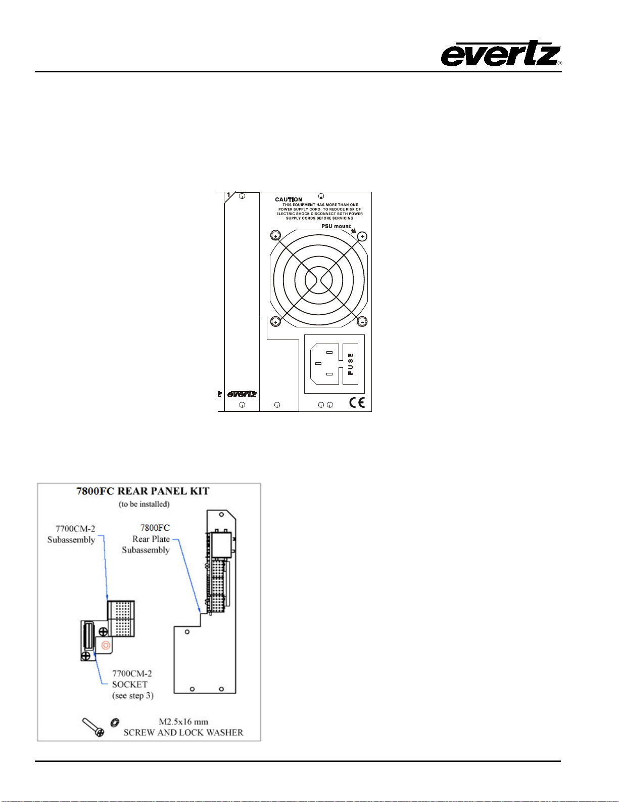
2.1. INSTALLING THE MODULE REAR PLATE .........................................................................2
2.2. INSTALLING AND REMOVING THE MODULE .................................................................... 4
2.3. REAR PANEL CONNECTIONS............................................................................................ 5
2.3.1. Ethernet Connection .................................................................................................. 5
2.3.2. GPI/O Connections....................................................................................................7
2.3.3. Serial I/O Connections...............................................................................................7
2.4. REPLACING THE BATTERY............................................................................................... 7
2.4.1. Safety Guidelines and Precautions Concerning the Use of 3V Lithium Batteries ...........8
3. SPECIFICATIONS........................................................................................................................ 9
3.1. ETHERNET ......................................................................................................................... 9
3.2. SERIAL I/O.......................................................................................................................... 9
3.3. ELECTRICAL ...................................................................................................................... 9
3.4. PHYSICAL (NUMBER OF SLOTS)....................................................................................... 9
4. STATUS INDICATORS............................................................................................................... 10
4.1. MODULE STATUS LEDS .................................................................................................. 10
4.2. DOT-MATRIX DISPLAY ..................................................................................................... 11
5. JUMPERS.................................................................................................................................. 12
5.1. SELECTING WHETHER LOCAL FAULTS WILL BE MONITORED BY THE GLOBAL
FRAME STATUS ............................................................................................................... 12
5.2. CONFIGURING THE MODULE FOR FIRMWARE UPGRADES........................................... 12
6. CONFIGURING THE FRAME CONTROLLER............................................................................. 13
6.1. ESTABLISHING COMMUNICATION WITH THE FRAME CONTROLLER........................... 13
6.1.1. Connecting the Computer to the Card Edge Serial Port............................................. 13
6.1.2. Terminal Program Setup.......................................................................................... 13
6.2.CONFIGURING THE NETWORK SETTINGS..................................................................... 14

7800 MultiFrame Manual
7800FC VistaLINK®Frame Controller
Revision 1.0
6.2.1. Network Setup .........................................................................................................15
6.2.2. SNMP Setup............................................................................................................17
6.2.2.1. SNMP V1 Setup..........................................................................................17
6.2.2.2. Community Strings......................................................................................17
6.2.2.3. Trap Setup ..................................................................................................18
6.2.2.4. SNMP V3 Setup..........................................................................................18
6.2.3. Exiting the Setup Menu.............................................................................................20
7. UPGRADING THE FRAME CONTROLLER IMAGE VISTALINK®................................................22
7.1. PROCEDURES FOR UPGRADING THE FRAME CONTROLLER IMAGE VISTALINK®.......22
7.2. REMOTE UPGRADE PROCEDURE USING VISTALINK®...................................................22
7.2.1. Downloading the 7800FC Frame Controller Image.....................................................22
7.2.2. Upgrading the Frame Controller Image using VistaLINK®...........................................23
7.3. SERIAL CARD EDGE UPGRADE PROCEDURE ................................................................24
7.3.1. Downloading Upgrade Files ......................................................................................25
7.3.2. Linking the Frame Controller to the Network Adapter .................................................25
7.3.3. Connecting the Computer to the Card Edge Serial Port..............................................25
7.3.4. Setting the 7800FC Frame Controller to Upgrade Mode.............................................25
7.3.5. Viewing Startup Information......................................................................................25
7.3.6. Upgrading the 7800FC Boot Loader ..........................................................................26
7.3.7. Upgrading the 7800FC Frame Controller...................................................................26
8. WEBEASY®WEB INTERFACE...................................................................................................29
8.1. UPGRADING CARDS USING WEBEASY®..........................................................................30
8.1.1. Upgrading Modules Using WebEASY®......................................................................30
8.1.2. Upgrading 7800FC Using WebEASY®......................................................................31

7800 MultiFrame Manual
7800FC VistaLINK®Frame Controller
Revision 1.0
Figures
Figure 1-1: 7800FC Block Diagram.................................................................................................... 1
Figure 2-1: 7800FR Rear Panel with Cover Plate Installed..................................................................2
Figure 2-2: 7800FR Rear Panel Kit Installation................................................................................... 3
Figure 2-3: 7800FC Rear Panel .........................................................................................................5
Figure 2-4: Crossover Cable Wiring Diagram...................................................................................... 7
Figure 4-1: 7800FC Status LED Location......................................................................................... 10
Figure 5-1: Location of Jumpers....................................................................................................... 12
Figure 7-1: FC shown in the Hardware Tree ..................................................................................... 23
Figure 7-2: Control Tab for the FC Configuration View ...................................................................... 24
Figure 7-3: Send File Window ......................................................................................................... 26
Figure 8-1: WebEASY®Home Page................................................................................................ 29
Figure 8-2: WebEASY®Firmware Upgrade Page............................................................................. 30
Figure 8-3: WebEASY®Firmware Upgrade Page for 7800FC ........................................................... 31
Tables
Table 2-1: Standard RJ45 Wiring Colour Codes for “Straight Through” Cables.....................................6
Table 2-2: Serial I/O Connector Pin Definitions................................................................................... 7
Table 6-1: 7700 Upgrade Cable (WA-S76)....................................................................................... 13
Table 6-2: Port Settings of the Terminal Program ............................................................................. 13

7800 MultiFrame Manual
7800FC VistaLINK®Frame Controller
Revision 1.0
This page left intentionally blank

7800 MultiFrame Manual
7800FC VistaLINK®Frame Controller
Revision 1.0
REVISION HISTORY
REVISION
DESCRIPTION
DATE
1.0
First Release
Feb 2014
Information contained in this manual is believed to be accurate and reliable. However, Evertz assumes no responsibility for the use thereof nor for the
rights of third parties, which may be affected in any way by the use thereof. Any representations in this document concerning performance of Evertz
products are for informational use only and are not warranties of future performance, either expressed or implied. The only warranty offered by Evertz
in relation to this product is the Evertz standard limited warranty, stated in the sales contract or order confirmation form.
Although every attempt has been made to accurately describe the features, installation and operation of this product in this manual, no warranty is
granted nor liability assumed in relation to any errors or omissions unless specifically undertaken in the Evertz sales contract or order confirmation.
Information contained in this manual is periodically updated and changes will be incorporated into subsequent editions. If you encounter an error,
please notify Evertz Customer Service department. Evertz reserves the right, without notice or liability, to make changes in equipment design or
specifications.

7800 MultiFrame Manual
7800FC VistaLINK®Frame Controller
Revision 1.0
This page left intentionally blank

7800 MultiFrame Manual
7800FC VistaLINK®Frame Controller
Revision 1.0 Page-1
1. OVERVIEW
The 7800FC VistaLINK® Frame Controller card provides a single point of access to communicate with
VistaLINK®-capable modules. The 7800FC VistaLINK®Frame Controller provides a 10BASE-T/100BASE-
TX/1000BASE-TX Ethernet port and communication is facilitated using Simple Network Management
Protocol (SNMP).
The 7800FC VistaLINK® Frame Controller handles all SNMP communications between the frame
(7800FR) and the network manager (NMS), and serves as a gateway to individual cards in the frame. The
7800FC VistaLINK®Frame Controller also provides an RS-232 serial port interface for customer
configurations.
Features:
•Complies with IEEE 802.3 10BASE-T, 100BASE-TX and 1000BASE-TX Ethernet standards
•1000Mb/s Gigabit Ethernet, 100Mb/s Fast Ethernet or 10Mb/s Ethernet data transfer, selected by
auto negotiation
•Full-duplex or half-duplex operation, selected by auto-negotiation
•RJ-45 connector for network cable connection
•RS-232 serial control port for configuration
•Card edge LEDs indicate module fault, microprocessor state, activity and link status
•Rear panel LEDs indicate Ethernet link, activity and speed
•Supports “ftp” upgrades for frame-wide firmware upgrades (product specific)
•Includes VistaLINK®PRO (VLPRO-C) module software configuration tool
•Provides frame/chassis status information through VistaLINK®including power supply status, frame
status, card insertion/removal counters, 7800FC software version number and LED control
•Provides an onboard web interface to directly control modules that support WebEASY®
Figure 1-1: 7800FC Block Diagram

7800 MultiFrame Manual
7800FC VistaLINK®Frame Controller
Page-2 Revision 1.0
2. INSTALLATION
The 7800FC Frame Controller module can only be installed into 7700FR-C, 7800FR and 7800FR-QT
frames that have been fitted with the proper module interconnect circuit board. These frames have an ‘L’
shaped cover plate installed, adjacent to the IEC power inlet connector as shown in Figure 2-1. If your
frame does not have this L shaped cover plate then the 7800FC Frame controller card cannot be installed
in this frame.
Figure 2-1: 7800FR Rear Panel with Cover Plate Installed
2.1. INSTALLING THE MODULE REAR PLATE
The 7800FC rear panel kit consists of a screw and lock
washer, and two sub-assemblies, the 7700CM-2
connector module and the 7800FC rear panel plate
which houses the appropriate connectors for the module
.
To install the 7800FC rear panel kit, locate slot 1 at the
right side of the frame’s rear panel. Remove the filler
plates from the slot as shown in step 1 of Figure 2-2.
Install the 7700CM-2 subassembly first. Remove the
screw PART 1 as shown in Step 2. Carefully align the
7700CM-2 socket with the frame header and press firmly
into place as shown in step 3. Secure the 7700CM-2
sub-
assembly with the M2.5x16 mm screw and M2.5
lock washer as shown in Step 4.
Orient the 7800FC plate so that the labeling is visible
when the plate is installed (see Step 5). Loosely fasten
the plate to the extrusions using the mounting screws
you removed in Step 1. You will tighten the screws after
the main module is installed.

7800 MultiFrame Manual
7800FC VistaLINK®Frame Controller
Revision 1.0 Page-3
Figure 2-2: 7800FR Rear Panel Kit Installation

7800 MultiFrame Manual
7800FC VistaLINK®Frame Controller
Page-4 Revision 1.0
2.2. INSTALLING AND REMOVING THE MODULE
In order to insert or remove modules you will have to open the front panel. Turn the two captive screws
located on the front panel counter clockwise several turns until they release completely from the front
extrusions. Carefully lower the front panel door so that the front edge of the door is lower than the rear of
the door.
To install the frame controller module, orient the module vertically such that the white card ejector is on the
bottom. Align the card with the card guide corresponding to the slot number where you installed the rear
panel plate. Carefully slide the module into the frame and press it completely into the rear panel
connectors. Make sure that the connectors are fully seated in the rear panel. When this is done, close the
front panel and then tighten the screws that hold the rear panel in place.
To remove the frame controller module, press the card ejector down to release the module from the back
panel connectors. Grasp the card using the card ejector and pull the module out from the frame. As the
card ejector goes past the front extrusion, you will have to pull it with slightly more force. Carefully place
the module in a safe place, free from static discharge.

7800 MultiFrame Manual
7800FC VistaLINK®Frame Controller
Revision 1.0 Page-5
2.3. REAR PANEL CONNECTIONS
Figure 2-3: 7800FC Rear Panel
2.3.1. Ethernet Connection
The 7800FC is designed to be used with either 10Base-T (10 Mbps), 100Base-TX (100 Mbps) also known
as Fast Ethernet, or 1000Base-TX (1000 MBps) twisted pair Ethernet cabling systems. When connecting
for 10Base-T systems, category 3, 4, or 5 UTP cable as well as EIA/TIA – 568 100ΩSTP cable may be
used. When connecting for 100Base-TX systems, category 5 UTP cable is required. When connecting
for 1000Base-T system, category 5, 5e, 6, or 7 UTP cable is required. The cable must be “straight-
through” with a RJ-45 connector at each end (See Table 2-1). Make the network connection by plugging
one end of the cable into the RJ-45 receptacle of the 7800FC and the other end into a port of the
supporting hub. When connecting a 7800FC directly to the Ethernet port on a computer you will have to
use a “crossover” cable as shown in Figure 2-4.

7800 MultiFrame Manual
7800FC VistaLINK®Frame Controller
Page-6 Revision 1.0
The straight-through RJ-45 cable can be purchased or can be constructed using the pinout information in
Table 2-1. A colour code wiring table is provided in Table 2-1 for the current RJ-45 standards (AT&T 258A
or EIA/TIA 258B colour coding shown). Also refer to the notes following the table for additional wiring
guide information.
Pin 1
Pin # Signal EIA/TIA 568A
AT&T 258A or
EIA/TIA 568B
10BaseT
or 100BaseT
1
Transmit +
White/Green
White/Orange
X
2
Transmit –
Green/White or White
Orange/White or Orange
X
3
Receive +
White/Orange
White/Green
X
4
N/A
Blue/White or Blue
Blue/White or Blue
Not used (required)
5
N/A
White/Blue
White/Blue
Not used (required)
6
Receive –
Orange/White or Orange
Green/White or Green
X
7
N/A
White/Brown
White/Brown
Not used (required)
8
N/A
Brown/White or Brown
Not used (required)
Table 2-1: Standard RJ45 Wiring Colour Codes for “Straight Through” Cables
Note the following cabling information for this wiring guide:
•Only two pairs of wires are used in the 8-pin RJ-45 connector to carry Ethernet signals
•Even though pins 4, 5, 7 and 8 are not used, it is mandatory that they be present in the cable
•10Base-T, 100Base-TX and 1000Base-TX use the same pins, a crossover cable made for one will also
work with the other
•Pairs may be solid colours and not have a stripe
•Category 5 cable must use Category 5 rated connectors
The maximum cable run between the 7800FC and the supporting hub is 300 ft (100 m). The maximum
combined cable run between any two end points (i.e. 7800FC and PC/laptop via network hub) is 675 feet
(205 m).
Devices on the Ethernet network continually monitor the receive data path for activity as a means of
checking that the link is working correctly. When the network is idle, the devices also send a link test
signal to one another to verify link integrity. The 7800FC rear panel is fitted with two LEDs to monitor the
Ethernet connection.
10/100/1000:This LED is ON and amber when a 1000Base-TX link is last detected. This LED is ON
and green when a 100Base-TX link is last detected. The LED is OFF when a 10Base-T
link is last detected (the LINK LED is ON). Upon power-up the LED is OFF as the last
detected rate is not known and therefore defaults to the 10Base-T state until rate detection
is completed.
LN/ACT:This dual purpose Green LED indicates that the 7800FC has established a valid linkage to
its hub, whether the 7800FC is sending or receiving data. This LED will be ON when the
7800FC has established a good link to its supporting hub. This gives you a good indication
that the segment is wired correctly. The LED will BLINK when the 7800FC is sending or
receiving data. The LED will be OFF if there is no valid connection.

7800 MultiFrame Manual
7800FC VistaLINK®Frame Controller
Revision 1.0 Page-7
If you are building a “crossover” cable you must wire it according to Figure 2-4:
Figure 2-4: Crossover Cable Wiring Diagram
2.3.2. GPI/O Connections
GP I/O: A 9 pin female ‘D’ connector for connection to external devices. (Currenlty this port is not used.)
2.3.3. Serial I/O Connections
SERIAL I/O:A 9 pin female 'D' connector for connection to a computer. (Currently this port is not used.)
Pin # Name Description
1
GND
Chassis ground
2
Tx
RS-232 Transmit Output
3
Rx
RS-232 Receive Input
4
5
Sig Gnd
RS-232 Signal Ground
6
7
RTS
RS-232 RTS Input
8
CTS
RS-232 CTS Output
9
Table 2-2: Serial I/O Connector Pin Definitions
2.4. REPLACING THE BATTERY
The Frame Controller is fitted with a 3V Lithium battery type CR2032. This battery is used to power non-
volatile memory of some of the frame controller’s parameters while power is removed from the frame.
Before attempting to change the battery remove power from the 7800FC card.
CAUTION
Danger of explosion if battery is incorrectly replaced.
Replace only with the same or equivalent type.

7800 MultiFrame Manual
7800FC VistaLINK®Frame Controller
Page-8 Revision 1.0
CAUTION
Danger of explosion if battery is exposed to excessive heat such as direct
sunlight, fire, etc.
2.4.1. Safety Guidelines and Precautions Concerning the Use of 3V Lithium Batteries
Please observe the following warnings strictly. If misused, the batteries may explode or leak, causing injury
or damage to the equipment.
•The batteries must be inserted into the equipment with the correct polarity (+ and -)
•Do not attempt to revive used batteries by heating, charging or other means
•Do not dispose of batteries in fire. Do not dismantle batteries
•Do not short circuit batteries
•Do not expose batteries to high temperatures, moisture or direct sunlight
•Do not place batteries on a conductive surface (anti-static work mat, packaging bag or form trays)
as it can cause the battery to short

7800 MultiFrame Manual
7800FC VistaLINK®Frame Controller
Revision 1.0 Page-9
3. SPECIFICATIONS
3.1. ETHERNET
Network Type: IEEE 802.3 (10BASE-T)
IEEE 802.3u (100BASE-TX)
IEEE 802.3ab (1000BASE-TX)
Connector: RJ-45
3.2. SERIAL I/O
Standard: RS-232
Connector: Female DB-9
Baud Rate: 115,200
Format: 8 bits, no parity, 2 stop bits, no flow control
3.3. ELECTRICAL
Voltage: + 12VDC
Power: 8 Watts
EMI/RFI: Complies with FCC Part 15
Class A and EU EMC directive
3.4. PHYSICAL (NUMBER OF SLOTS)
350FR: 1
7700FR-C: 1
7800FR: 1

7800 MultiFrame Manual
7800FC VistaLINK®Frame Controller
Page-10 Revision 1.0
4. STATUS INDICATORS
The 7800FC has 5 LED Status indicators on the front card edge to show operational status of the card at a
glance. Figure 4-1 shows the location of the LEDs and card edge controls.
7800FC
Shaft
Encoder
Module OK
LED
Status Display
USB Port
Serial Upgrade
Port
Diagnostic
LEDs
1
2
3
Local Fault
LED
Figure 4-1: 7800FC Status LED Location
4.1. MODULE STATUS LEDS
Two large LEDS on the front of the main board indicate the general health of the module:
LOCAL FAULT: This Red LED indicates poor module health or if a local input power fault exists (i.e.:
a blown fuse). The LOCAL FAULT indication can also be reported to the frame
through the FRAME STATUS jumper.
MODULE OK: This Green LED indicates good module health. It will be ON when the board power
is good.
The remaining LEDs have no functionality at this time.

7800 MultiFrame Manual
7800FC VistaLINK®Frame Controller
Revision 1.0 Page-11
4.2. DOT-MATRIX DISPLAY
Additional signal status monitoring of the card’s parameters is provided via the 4-character alphanumeric
status display located on the card edge.
When the card is initially inserted, it will display the message BOOT and then the message EXEC. This
indicates that the 7800FC is running through its bootup sequence and executing the application code.
Once the application code is completely loaded and ready to use, it will display the message FC.
If the shaft encoder is pressed in, the display will cycle through the firmware version and the IP address of
the 7800FC.

7800 MultiFrame Manual
7800FC VistaLINK®Frame Controller
Page-12 Revision 1.0
5. JUMPERS
MODULE STATUS +12V
UPGRADE
J4
J9
J8
ON
EVERTZ (1) 7800FC
GND
OFF
BUS
RUN
Figure 5-1: Location of Jumpers
5.1. SELECTING WHETHER LOCAL FAULTS WILL BE MONITORED BY THE GLOBAL
FRAME STATUS
BUS:The BUS jumper J8 located near the top middle of the module determines whether local
faults (as shown by the Local Fault indicator) will be connected to the 7700FR-C, 7800FR
or 7800FR-QT frame's global status bus.
To monitor faults on this module with the frame status indicators (on the Power Supply
FRAME STATUS LEDs and on the Frame's Fault Tally output) install this jumper in the On
position. (Default)
When this jumper is installed in the Off position, local faults on this module will not be
monitored.
5.2. CONFIGURING THE MODULE FOR FIRMWARE UPGRADES
UPGRADE:The UPGRADE jumper J4 located behind the serial port header J9 is used when firmware
upgrades are being done to the module. For normal operation it should be installed in the
RUN position. See the Upgrading Firmware section 7 for more information.

7800 MultiFrame Manual
7800FC VistaLINK®Frame Controller
Revision 1.0 Page-13
6. CONFIGURING THE FRAME CONTROLLER
The 7800FC Frame Controller is configured by connecting its serial port to a computer running a readily
available terminal program such as HyperTerminal. The following procedure will guide you through each
step of the configuration process.
You will need the following equipment in order to configure the 7800FC Frame Controller:
•PC with available communications port. The communication speed is 115200 baud
•“Straight-thru” serial extension cable (DB9 female to DB9 male) or (DB25 female to DB9 male)
•Terminal program such as HyperTerminal
•Special upgrade cable supplied with the 7700FR-C, 7800FR or 7800FR-QT frame. This cable is
normally in the vinyl pouch at the front of this manual. (Evertz part #WA S76).
6.1. ESTABLISHING COMMUNICATION WITH THE FRAME CONTROLLER
6.1.1. Connecting the Computer to the Card Edge Serial Port
Connect the supplied serial upgrade cable to the 2x3 header (J9) at the front edge of the 7800FC card.
Note that pins 1 and 5 on the header should be removed and pins 1 and 5 on the cable connector should
also be plugged. If the cable is not keyed, make sure that you install it so that the cable is towards the front
of the frame when the module is installed (i.e. so that it passes over the card ejector). Pin 1 of the ribbon
cable is brown and will be facing the bottom ejector side of the module when the cable is correctly
installed.
7800FC End
PC End
2 row X
3 pin Berg
Pin 6 Conductor
Ribbon Cable
9 pin D
Female
Pin
Key
1
Blue
1
Rx
2
Green
Tx
2
Tx
3
Yellow
Rx
3
Tx Gnd
4
Orange
Gnd
5
Key
5
Red
---
6
Brown
Table 6-1: 7700 Upgrade Cable (WA-S76)
6.1.2. Terminal Program Setup
1. Start the terminal program and configure the port settings of the terminal program as follows:
Baud
115200
Data bits
8
Parity
no
Stop bits
2
Flow Control
no
Table 6-2: Port Settings of the Terminal Program

7800 MultiFrame Manual
7800FC VistaLINK®Frame Controller
Page-14 Revision 1.0
2. Install the 7800FC card into the frame. After the card powers up and the boot-up messages are
finished, a “login” prompt will appear in the terminal window. (For future reference 7800FC
software version information is displayed prior to the “login” prompt and should be quoted to Service
staff when required.)
For example:
Kernel Build Date : Jan 28, 2013
Software : v1.2 Build 2
Tag : 7801FC_r1-2-2
Software Build Date : Jan 30, 2013
Wed Jan 30 11:05:46 GMT 2013
NetBSD/evbppc (780xfc) (console)
login:
3. If the prompt does not appear, the following is a list of possible reasons for failed communications:
•Defective Serial Upgrade cable.
•Wrong communications port selected in the terminal program.
•Improper port settings in the terminal program. (Refer to step 1 for settings).
4. At the “login” prompt, enter:
•“customer” for user name <Enter>
•“customer” for password <Enter>
NOTE - Neither username nor password can be modified at the time of this manual
revision release.
5. A menu for Network, SNMP and FC Upgrade Setup Configuration appears and is detailed in the
next section.
6.2. CONFIGURING THE NETWORK SETTINGS
From main menu, three selections are available - Network Setup, SNMP Setup.
•Network Setup is used to set network IP addresses as well as broadcasting and routing instructions
•SNMP Setup is used to identify up to ten trap destination IP addresses.
**** Main Menu ****
<1> Network Setup
<2> SNMP Setup
<X> Exit
<W> Exit without saving to flash
>
Other manuals for 7800
5
This manual suits for next models
1
Table of contents
Other evertz Controllers manuals
Popular Controllers manuals by other brands

Rockwell Automation
Rockwell Automation MagneMotion 700-0871-00 user manual

Digital Equipment
Digital Equipment DEC WANcontroller 622 Problem Solving

Colorlight
Colorlight X16 user manual

Yudian
Yudian AI-516 operation instruction

Bibby Sterilin
Bibby Sterilin Techne TU-20D Operator's manual

LED World
LED World WiFi-103 installation instructions