evertz MultiFrame EMX3 User manual

EMX3/EMX6/3000FR/3700 MultiFrame Manual
3080IPG-HD High Density IP Gateway
Revision 1.0 Page i
TABLE OF CONTENTS
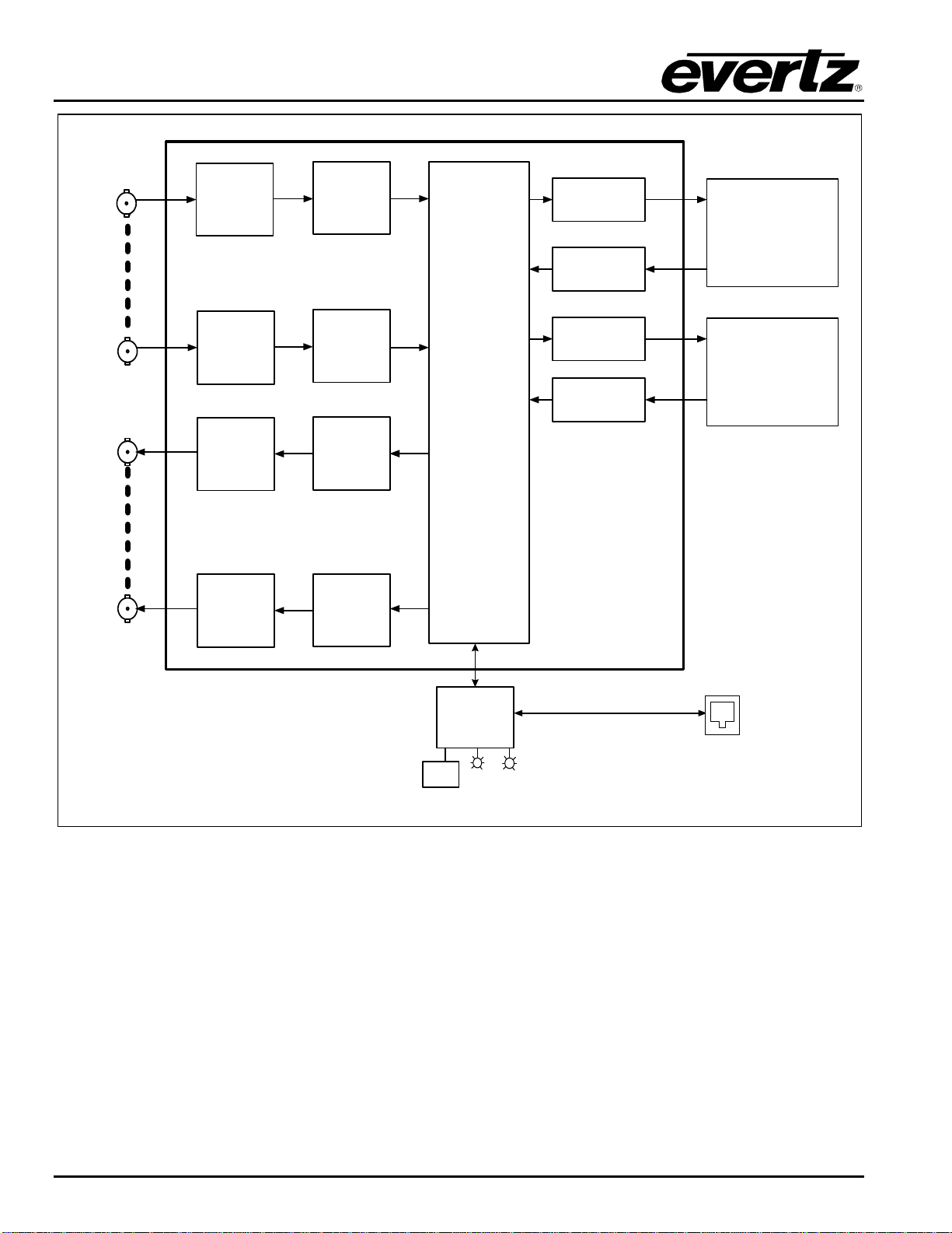
1. OVERVIEW ...................................................................................................................................1
2. SPECIFICATIONS.........................................................................................................................3
2.1. INPUTS AND OUTPUS.........................................................................................................3
2.2. ENCAPSULATION PARAMETERS......................................................................................3
2.3. DE-ENCAPSULATION PARAMETERS................................................................................3
2.4. TSM LITE MONITORED PARAMETERS..............................................................................3
2.5. PHYSICAL (MAXIMUM NUMBER OF CARDS)....................................................................3
3. INSTALLATION.............................................................................................................................4
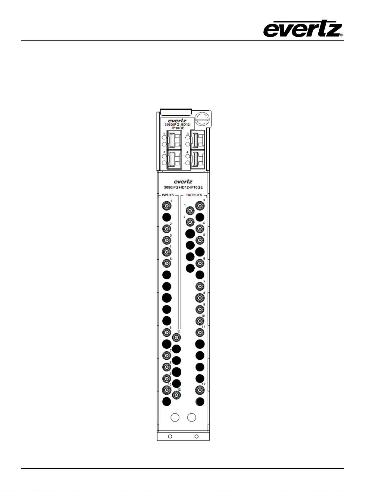
3.1. REAR PLATE DESCRIPTION..............................................................................................4
3.1.1. Video Connections.....................................................................................................5
3.1.2. Frame Controller Ethernet Connection.......................................................................5
3.2. HARDWARE INSTALLATION..............................................................................................6
3.3. CONFIGURING THE BASIC NETWORK SETTINGS...........................................................8
4. CARD CONFIGURATION ...........................................................................................................10
4.1. CONNECTING TO VLPRO.................................................................................................10
4.2. MAIN CONTROL TAB........................................................................................................11
4.3. INPUT TO IP CONTROL.....................................................................................................13
4.3.1. IP Output Control Tab..............................................................................................13
4.3.2. SDI Input Monitor Tab..............................................................................................14
4.3.3. Misc. Faults Tab ......................................................................................................15
4.3.4. Port Control Panel ...................................................................................................15
4.3.5. Monitor Tab .............................................................................................................16
4.3.6. Input to IP Redundancy ...........................................................................................17
4.4. IP TO OUTPUT CONTROL.................................................................................................17
4.4.1. Redundancy Control Tab.........................................................................................17
4.4.2. Port Clarification ......................................................................................................18
4.4.3. Port Control Tab ......................................................................................................18
4.4.4. Monitor Tab .............................................................................................................19
4.4.5. IP to Output Redundancy.........................................................................................20
4.5.
DEVICE REDUNDANCY.....................................................................................................21
5. TROUBLESHOOTING.................................................................................................................23
5.1. UPDATING VLPRO SERVER JAR FILE............................................................................23

EMX3/EMX6/3000FR/3700 MultiFrame Manual
3080IPG-HD High Density IP Gateway
Page ii Revision 1.0
Figures
Figure 1-1: 3080IPG-HD Block Diagram..........................................................................................................2
Figure 3-1: Rear Plate for 3080IPG-HD12-IP10GE.........................................................................................4
Figure 3-2: Serial Connection for 3080IPT-HD................................................................................................6
Figure 3-3: 3080IPG-HD TeraTerm Main Menu...............................................................................................7
Figure 3-4: Network Configuration for 3080IPG-HD ........................................................................................8
Figure 4-1: Ethernet Data Port Parameters ...................................................................................................11
Figure 4-2: Ethernet Monitor Main/Redundant...............................................................................................12
Figure 4-3: SNMP Trap Destination...............................................................................................................13
Figure 4-4: Input to IP Redundancy Control...................................................................................................13
Figure 4-5: Misc. Monitor Tab ........................................................................................................................14
Figure 4-6: Misc. Fault Tab ............................................................................................................................15
Figure 4-7: Input to IP Port Control ................................................................................................................15
Figure 4-8: Input to IP Monitoring...................................................................................................................16
Figure 4-9: Input to IP Port Redundancy Block Diagram...............................................................................17
Figure 4-10: IP to Output Redundancy Control..............................................................................................18
Figure 4-11: IP to Output Port Control ...........................................................................................................18
Figure 4-12: IP to Output Monitoring..............................................................................................................20
Figure 4-13: IP to Output Redundancy Block Diagram..................................................................................21
Figure 4-14: Unit Redundancy Block Diagram...............................................................................................22
Figure 6-1: VistaLINK®PRO Server...............................................................................................................23
Figure 6-2: VistaLINK®PRO – Applying JAR Updates..................................................................................24
Tables
Table 3-1: Standard RJ-45 Wiring Colour Codes............................................................................................. 5

EMX3/EMX6/3000FR/3700 MultiFrame Manual
3080IPG-HD High Density IP Gateway
Revision 1.0 Page iii
REVISION HISTORY
REVISION DESCRIPTION DATE
1.0 First Release Apr 2014
Information contained in this manual is believed to be accurate and reliable. However, Evertz assumes no responsibility for the use thereof nor for
the rights of third parties, which may be affected in any way by the use thereof. Any representations in this document concerning performance of
Evertz products are for informational use only and are not warranties of future performance either express or implied. The only warranty offered by
Evertz in relation to this product is the Evertz standard limited warranty, stated in the sales contract or order confirmation form.
Although every attempt has been made to accurately describe the features, installation and operation of this product in this manual, no warranty is
granted nor liability assumed in relation to any errors or omissions unless specifically undertaken in the Evertz sales contract or order confirmation.
Information contained in this manual is periodically updated and changes will be incorporated into subsequent editions. If you encounter an error,
please notify Evertz Customer Service department. Evertz reserves the right, without notice or liability, to make changes in equipment design or
specifications.

EMX3/EMX6/3000FR/3700 MultiFrame Manual
3080IPG-HD High Density IP Gateway
Page iv Revision 1.0
This page left intentionally blank

EMX3/EMX6/3000FR/3700 MultiFrame Manual
3080IPG-HD High Density IP Gateway
OVERVIEW Revision 1.0 Page - 1
1. OVERVIEW
The 3080IPG-HD is a complete high density hardware solution for 3G/HD/SD SDI video to IP conversion,
and vice-versa. As more providers are delivering contribution and distribution quality video over IP
networks, the 3080IPG-HD is capable of effectively bridging the traditional SDI video world with IP
networks.
Controlled by the industry leading VistaLINK®PRO, the 3080IPG-HD offers signal providers the capability
to encapsulate any HD SDI video payloads to a unicast or multicast standardized IP stream. The
3080IPG-HD is also capable of receiving IP streams and de-encapsulating to 3G/HD/SD SDI.
The 3080IPG-HD supports several forms of redundancy scenarios in accordance to today’s broadcasters
needs. With these features, the 3080IPG-HD can be used in conjunction with any other Evertz equipments
like Audio/Video Routers, and Multiplexers in a fully redundant System. The failover features are
implemented when a link loss, or a UDP loss occur.
Coupled with the 3080IPX 640Gb/s Multicast tunnels switching fabric, in LAN applications the 3080IPG-
HD allows users to build a large scale distributed routing solution over 10GE with the benefits of direct
conversion to optics and reduction in cable count by a factor of 6x.
The 3080IPG-HD platform provides 3G/HD/SD SDI inputs and outputs over DIN connectors and network
interfaces via SFP+ cages each capable of 10GigE.
The 3080IPG-HD occupies two card slots and can be housed in a 3RU frame which will hold up to 2
modules, 6RU frame which will hold up to 7 modules, and 3000/3700 frame which will hold up to 3
modules.
Applications include:
•Bridging traditional coaxial networks with emerging video over 10GigE IP networks
•3G/HD/SD SDI to IP encapsulation
•IP to 3G/HD/SD SDI de-encapsulation
•UDP or RTP input/output
•IP network with QoS, VLAN and DiffServ
•10GbE Port, Device Redundancy
Features:
•Fully integrated with the Industry leading Evertz VistaLINK®Pro NMS system
•2x 10GigE IP Ports for 3080IPG-HD6-IP10GE or 4x 10GigE IP ports for 3080IPG-HD12-IP10GE
•12xSDI Input and 12xSDI Output Ports for 3080IPG-HD12-IP10GE (6 for the 3080IPG-HD6-
IP10GE)
•3G/HD/SD SDI to IP conversion, and vise versa
•Direct module control via SNMP (separate IP port)
•Auto fail-over to the redundant incoming Transport Streams over IP

EMX3/EMX6/3000FR/3700 MultiFrame Manual
3080IPG-HD High Density IP Gateway
Page - 2 Revision 1.0 OVERVIEW
CPU
Controller VistaLINK
Control
10/100 RJ45
Card
Edge
Input
Present
Module
Status
Cross
Point
Switch
3G/HD/SD
SDI
Input 1 Equalizer Input
Monitor
3G/HD/SD
SDI
Input 12 Equalizer Input
Monitor
3G/HD/SD
SDI
Output 1
Cable
Driver
3G/HD/SD
SDI
Output 12
Cable
Driver
Output
Monitor
Output
Monitor
IP
Encapsulators
IP
Decapsulators
IP
Encapsulators
IP
Decapsulators
10GE – SFP+ Cage
10GE – SFP+ Cage
Figure 1-1: 3080IPG-HD Block Diagram

EMX3/EMX6/3000FR/3700 MultiFrame Manual
3080IPG-HD High Density IP Gateway
SPECIFICATIONS Revision 1.0 Page - 3
2. SPECIFICATIONS
2.1. INPUTS AND OUTPUS
•6xSDI or 12xSDI SD, HD, or 3G input
•6xSDI or 12xSDI SD, HD, or 3G output
•Min SDI input bitrate 270Mb/s
•Max SDI input bitrate 2.97Gb/s
•2xSFP+ (3080IPG-HD6-IP10GE), or 4xSFP+ (3080IPG-HD12-IP10GE) 10GigE I/O for transport
stream over IP
2.2. ENCAPSULATION PARAMETERS
•IP encapsulation for each SDI input:
oMAC 802.3>IPV4>UDP>RTP>Transport Stream (RTP can be turned on and off)
o7 Transport Stream packets per IP frame
•IP address (IP, Subnet mask, Gateway) for the source
•IP address for the destination (Unicast and Multicast)
•Selection of the source port and destination port
•Set Local MAC address of the equipment
2.3. DE-ENCAPSULATION PARAMETERS
•Join Multicast by providing correct messaging using IGMP V2/V3 (SSM Support)
•Selection of the UDP Ports
2.4. TSM LITE MONITORED PARAMETERS
•Total Bitrate
•Null Packet Bitrate
•TS_sync_loss
•Continuity count error
2.5. PHYSICAL (MAXIMUM NUMBER OF CARDS)
3000FR: 3
3700FR: 3
EMX3: 2
EMX6: 7

EMX3/EMX6/3000FR/3700 MultiFrame Manual
3080IPG-HD High Density IP Gateway
Page - 4 Revision 1.0 INSTALLATION
3. INSTALLATION
3.1. REAR PLATE DESCRIPTION
The 3080IPG-HD comes standard with a companion +6RU rear plate. Figure 2-1 provides an illustration of
the 3080IPG-HD rear plate.
Figure 3-1: Rear Plate for 3080IPG-HD12-IP10GE

EMX3/EMX6/3000FR/3700 MultiFrame Manual
3080IPG-HD High Density IP Gateway
INSTALLATION Revision 1.0 Page - 5
3.1.1. Video Connections
SDI IN: Each BNC connector input is compatible with SMPTE SDI standards.
SDI OUT: Each BNC connector output is compatible with SMPTE SDI standards
3.1.2. Frame Controller Ethernet Connection
The IPG Series uses 10Base-T (10 Mbps), 100Base-TX (100 Mbps) or Gigabit (1Gbps) twisted pair
Ethernet cabling systems. When connecting for 10Base-T systems, category 3, 4, or 5 UTP cable as well
as EIA/TIA – 568 100ΩSTP cable may be used. When connecting for 100Base-TX systems, category 5
UTP cable is required. The cable must be “straight-through” with an RJ-45 connector at each end.
Establish the network connection by plugging one end of the cable into the RJ-45 receptacle of the Frame
Controller of the chassis and the other end into a port of the supporting hub.
The straight-through RJ-45 cable can be purchased or can be constructed using the pin-out information in
Table 2-1. A colour coded wiring table is provided in Table 2-1 for the current RJ-45 standards (AT&T
258A or EIA/TIA 258B colour coding shown). Also refer to the notes following the table for additional
wiring guide information.
Pin
1
Pin # Signal EIA/TIA 568A
AT&T 258A or
EIA/TIA 568B
10BaseT
or 100BaseT
1
Transmit +
White/Green
White/Orange
X
2
Transmit –
Green/White or White
Orange/White or Orange
X
3
Receive +
White/Orange
White/Green
X
4
N/A
Blue/White or Blue
Blue/White or Blue
Not used (required)
5
N/A
White/Blue
White/Blue
Not used (required)
6
Receive –
Orange/White or Orange
Green/White or Green
X
7
N/A
White/Brown
White/Brown
Not used (required)
8
N/A
Brown/White or Brown
Not used (required)
Table 3-1: Standard RJ-45 Wiring Colour Codes
Note the following cabling information for this wiring guide:
•Only two pairs of wires are used in the 8-pin RJ-45 connector to carry Ethernet signals.
•Even though pins 4, 5, 7 and 8 are not used, it is mandatory that they be present in the cable.
•10BaseT and 100BaseT use the same pins (a crossover cable made for one will also work with the
other).
•Pairs may be solid colors and not have a stripe.
•Category 5 cable must use Category 5 rated connectors.
The maximum cable run between the router and the supporting hub is 300 ft (90 m). The maximum
combined cable run between any two end points (i.e. router and PC/laptop via network hub) is 675 feet
(205 m).
Devices on the Ethernet network continually monitor the receive data path for activity as a means of
checking that the link is working correctly. When the network is idle, the devices also send a link test
signal to one another to verify link integrity. The rear panel is fitted with two LEDs to monitor the Ethernet
connection.

EMX3/EMX6/3000FR/3700 MultiFrame Manual
3080IPG-HD High Density IP Gateway
Page - 6 Revision 1.0 INSTALLATION
1000: This Amber LED is ON when a 100Base-TX link is last detected. The LED is OFF when a
10Base-T link is last detected (the LINK LED is ON). Upon power-up the LED is OFF as the
last detected rate is not known and therefore defaults to the 10Base-T state until rate
detection is completed.
LN/ACT: This dual purpose Green LED indicates that the card has established a valid linkage to its
hub, and whether the module is sending or receiving data. This LED will be ON when the
module has established a good link to its supporting hub. This gives you a good indication
that the segment is wired correctly. The LED will BLINK when the module is sending or
receiving data. The LED will be OFF if there is no valid connection.
3.2. HARDWARE INSTALLATION
To successfully install the 3080IPG-HD, the following is required:
1. Unused IP address on the network or a DHCP server.
2. Evertz serial cable.
3. VistaLINK® PRO Server IP address.
Before handling the card it is important to minimize the potential effects of static electricity. It is therefore
recommended that an ESD strap be worn.
Locate on the chassis 2 adjacent vacant slots. Unpack the 3080IPG-HD and separate the rear panel from
the main card. Locate on the rear of the rack the two slots and remove the blanking panels. Insert the rear
panel into the back of the chassis and secure using the four screws provided.
Figure 3-2: Serial Connection for 3080IPT-HD

EMX3/EMX6/3000FR/3700 MultiFrame Manual
3080IPG-HD High Density IP Gateway
INSTALLATION Revision 1.0 Page - 7
Before inserting the front card, connect the serial cable to the board using the serial cable provided (See
Fig. 3-2 for reference). Now insert the 3080IPG-HD card into the corresponding front slots ensuring the
card lines up with the slot runners on the bottom and the top of the chassis. Push the card firmly into the
slot ensuring that when it mates with the rear card, and it has been firmly pushed into a seated position.
Do not connect any cables to the rear card (failure to do this could cause unwanted network issues) until
the initial configuration has been completed.
Connect the 9-pin d-type end of the serial cable to the serial port of your computer. Open a Terminal
session and configure the port for the following configuration:
Click OK to apply these settings and press the return key. The session should respond with the 3080IPG-
HD Main Menu (see Fig. 3-3):
Figure 3-3: 3080IPG-HD TeraTerm Main Menu
(1) Network Configuration
This sub-menu enables the user to configure the control network settings for the card. Configuring this
sub-menu allows the user to access the card through the VistaLINK®PRO Client interface.
(2) SNMP Configuration
This sub-menu enables the user to configure the Simple Network Management Protocol settings. In this
menu you can set or remove the SNMP trap IP address and the SNMP Read and Set community strings.
(3) Data Network Configuration
This sub-menu is used to configure the data port settings. This configuration is also performed via
VistaLINK®PRO will not be covered in this section.
Bits per second
115200
Data Bits
8
Parity
None
Stop Bits
2
Flow Control
None

EMX3/EMX6/3000FR/3700 MultiFrame Manual
3080IPG-HD High Density IP Gateway
Page - 8 Revision 1.0 INSTALLATION
(4) Input/Output Configuration
This sub-menu is used to configure and monitor the Unicast/Multicast IP input/output streams, as well as
the SDI input streams. This configuration is also performed via the VistaLINK®PRO client and will not be
covered in this section.
(5) Trace – Engineering Only
This menu is for Evertz personnel only. You may be requested to access and execute options within this
menu when seeking technical support from Evertz. Guidance will be given should this be required.
(6) Engineering/Debug
This menu is for Evertz personnel only. You may be requested to access and execute options within this
menu when seeking technical support from Evertz. Guidance will be given should this be required.
Before it is possible to configure the card via VistaLINK® PRO it is first necessary to configure the initial
basic network settings via the serial cable. Refer to section 3.3.
3.3. CONFIGURING THE BASIC NETWORK SETTINGS
Select option (1) Network Configuration, the Network Configuration menu will be displayed as shown in
Fig 3-3. If you prefer to use DHCP then you may select option (5) Set DHCP/Hotswap mode, and then
continue from step 4:
1. Select option (1) Set IP Address and configure the IP address for the 3080IPG-HD ensuring that
the IP address is not already in use on the network.
2. Now select option (2) Set Netmask and configure the correct subnet mask for your network.
3. If required also configure option (3) Set Gateway and (4) Set Broadcast Address.
4. Exit from the Network Configuration menu using (S) Save and Exit, NOT (X) Exit.
Figure 3-4: Network Configuration for 3080IPG-HD

EMX3/EMX6/3000FR/3700 MultiFrame Manual
3080IPG-HD High Density IP Gateway
INSTALLATION Revision 1.0 Page - 9
From the Main Menu, select option (2) SNMP Configuration. Select option (1) Set IP Address and enter
the IP address of your VistaLINK®PRO Server. Exit using option (S) Save and Exit, now extract the card
from the rack, remove the serial cable and re-insert it.
NOTE: These changes will not take effect unless the 3080IPG-HD is power cycled.
You have now completed the minimum necessary network configuration and can connect the cables to the
rear card when ready.

EMX3/EMX6/3000FR/3700 MultiFrame Manual
3080IPG-HD High Density IP Gateway
Page - 10 Revision 1.0 CARD CONFIGURATION
4. CARD CONFIGURATION
4.1. CONNECTING TO VLPRO
This chapter assumes that the VistaLINK®PRO server and client are already configured for your network
and you have basic knowledge of the VistaLINK®PRO interface. It also assumes that the user or network
administrator has already added the appropriate jar file to the server, and both the client and server
applications have been restarted. Please refer to the VistaLINK®PRO manual for instruction on how to
load a jar file. If you are the network administrator refer to section 5.1 for information on updating the
VistaLINK®PRO Server Jar File.
Open VistaLINK®PRO and click on the refresh tree icon. Expand the hardware tree by clicking on the “+”
button. Your card should appear as a newly listed device with its IP address used to configure the card in
Step 3.2 above. It may take up to a minute to appear while the card and switch negotiate network settings
(this can be verified directly on the switch if necessary). Please note that the 3080IPG-HD will identify two
items under the IP address in the navigation tree: Input to IP and IP to Output sub menu. Select the “+”
button beside “Inputs to IP” to expand the IP output list. Select the “+” button beside the “IP to Outputs”
option to expand the IP input list. Ensure that these tabs are present to confirm that the proper jar file is
loaded. The user will be required to individually select each item to configure the appropriate function.
Note: If after a couple of minutes the card has still not appeared, try selecting Add
Agent from the Tree> Add/Update Agent menu. Enter the IP address and select
OK. The card should now be listed and will remain grayed out for a moment while
VistaLINK®PRO finds the card and confirms its configuration.
Please consult your network administrator if you continue to have problems connecting the card with
VistaLINK®PRO, alternatively contact Evertz Microsystems Ltd. or your authorized reseller for technical
support.
Right click the IP address or the sub-modules of the 3080IPG-HD to access and configure their
parameters. Select “View Configuration” from one of the modules available (Input to IP, or IP to Output).
The configuration page will open, enabling the user to toggle the configuration tabs in order to configure
the parameters of the 3080IPG-HD. See sections 4.2 to 4.4 to provide an explanation of the functions and
features of the 3080IPG-HD card.

EMX3/EMX6/3000FR/3700 MultiFrame Manual
3080IPG-HD High Density IP Gateway
CARD CONFIGURATION Revision 1.0 Page - 11
4.2. MAIN CONTROL TAB
Right click the IP address and select “View Configuration” to open the configuration dialogue box (see Fig.
4-1) and set Ports 1, 2, 3, and 4’s Data Port IP parameters.
Figure 4-1: Ethernet Data Port Parameters
Note: The physical SDI input/output DIN connectors 1-6 are used with physical IP
slots “SFP1 & SFP2”, while SDI DIN connectors 7-12 are used with IP slots “SFP3
& SFP4”. These name assignments are shown on the rear-plate.
Selecting the tab entitled “Ethernet Monitor Main/Redundant” (see Fig. 4-2) shows the 10GigE link status
as well as multiple monitoring options for each individual port:
•Received/Transmitted Bandwidth: The incoming/outgoing transport stream bandwidth on the
specific port

EMX3/EMX6/3000FR/3700 MultiFrame Manual
3080IPG-HD High Density IP Gateway
Page - 12 Revision 1.0 CARD CONFIGURATION
•Error-Free Frames Received/Transmitted: The total number of error-free frames
received/transmitted from the transport stream.
•Erroneous Frames Received/Transmitted: The total number of frames with errors
received/transmitted from the transport stream.
•Broadcast Frames Received/Transmitted: The total number of broadcast frames
received/transmitted on the transport stream.
•Unicast Frames Received/Transmitted: The total number of Unicast frames
received/transmitted on the transport stream.
•Multicast Frames Received/Transmitted: The total number of Multicast frames
received/transmitted on the transport stream.
Figure 4-2: Ethernet Monitor Main/Redundant
Selecting the “SNMP Trap Destination” tab allows the User to add the IP address of the SNMP monitoring
agent. This will inform the user of any traps that triggered.

EMX3/EMX6/3000FR/3700 MultiFrame Manual
3080IPG-HD High Density IP Gateway
CARD CONFIGURATION Revision 1.0 Page - 13
•Add Trap Destination: Input for the IP address of the SNMP monitoring agent
•Current Trap Destination: Displays the currently used IP address’ of the SNMP monitoring agent
Figure 4-3: SNMP Trap Destination
4.3. INPUT TO IP CONTROL
Select the “+” option beside the “Input to IP” submenu to expand this view to see the numbered physical
SDI input ports (6 or 12 dependant on your 3080IPG-HD model). These numbered inputs coincide with the
same numbered SDI input ports on the 3080IPG-HD rear-plate. Open the desired SDI input by right
clicking and selecting “View Configuration”, which will allow for IP output configuration for this SDI input
stream.
4.3.1. IP Output Control Tab
Figure 4-4: Input to IP Redundancy Control
•IP Tx Redundancy Mode: This feature allows the user to set which Tx Redundancy mode is active
for the outgoing IP stream:

EMX3/EMX6/3000FR/3700 MultiFrame Manual
3080IPG-HD High Density IP Gateway
Page - 14 Revision 1.0 CARD CONFIGURATION
oOff – Allows both ports to simultaneously stream the same content with different destination
IP addresses (when both ports are enabled)
oManual – Allows the user to select which port will stream the content
oRevertive – If both ports are enabled, Main will be used to stream the content until a link
loss occurs. The content will be streamed from the Redundant port until the link is returned
to the Main port. The link restoration to the Main port will automatically switch the stream to
transmit from Port 1
oNon-Revertive – If both ports are enabled, Main will be used to stream the content until a
link loss occurs. The content will be streamed from the Redundant port until a link failure
occurs on the Redundant port and the link is restored on to the Main port without errors.
•IP Tx Active Ethernet Port: Control to select which port will be used to stream content when the
Redundancy Mode is set to Manual.
•IP Tx Redundancy Port Loss Timeout: Sets the amount of time (in seconds) that will cause a
port failover if the port status is lost.
4.3.2. SDI Input Monitor Tab
Figure 4-5: Misc. Monitor Tab
•Presence: Displays if the SDI input is Locked (available) or Lost (unavailable)
•Input Video Standard: Displays the Video standard of the incoming Stream
•IP Tx Active Ethernet Port: Displays the active port that is currently streaming content (valid
when IPTx Redundancy mode is set to “on”)

EMX3/EMX6/3000FR/3700 MultiFrame Manual
3080IPG-HD High Density IP Gateway
CARD CONFIGURATION Revision 1.0 Page - 15
4.3.3. Misc. Faults Tab
Figure 4-6: Misc. Fault Tab
•Input Presence Trap: Selecting this trap enables a notification if the input SDI stream is Lost. This
notification will be sent to the IP address defined in the SNMP Trap Destination IP Address (see
Fig. 4-3)
4.3.4. Port Control Panel
Each physical IP output port can stream one copy of the incoming SDI stream. The 3080IPG-HD has the
ability to create a main and backup IP stream, which can be used as a fail over redundancy measure with
equipment further down the network path.
Figure 4-7: Input to IP Port Control
•Enable: Control to enable or disable the Port output
•Sources IP Address: Enter the source IP address associated with this stream. This address can
be the physical IP address of your data port, or any other address that you may want to be
encapsulated within the IP packets.

EMX3/EMX6/3000FR/3700 MultiFrame Manual
3080IPG-HD High Density IP Gateway
Page - 16 Revision 1.0 CARD CONFIGURATION
•Sources UDP Port (0 to 65535): Enter the source UDP port number for the IP address entered
above.
•Destination IP Address: Enter the Unicast or a Multicast (Destination) IP address. Multicast
addresses should be in the range of 224.0.0.0 through 239.255.255.255.
•Destination UDP Port (0 to 65535): Enter the destination UDP port number for the destination IP
address entered above.
•Type of Service (ToS): Enter the ToS value, if your network does not support ToS, use zero as
default.
•TTL: Use this slider to set the Time to Live (TTL) value. Using the Multicast IP protocol, the TTL
value indicates the scope or range in which a packet may be forwarded. By convention:
0 is restricted to the same host
1 is restricted to the same subnet
32 is restricted to the same site
64 is restricted to the same region
128 is restricted to the same continent
255 is unrestricted
•RTP Mode: Use this drop down box to enable (On) or disable (Off) the use of RTP. The use of
RTP is recommended as it provides services such as time stamping, sequence numbering and
delivery monitoring, which can be beneficial for real-time delivery systems.
•TS Packets/ IP Frame: This field enables the user to enter the number of transport stream packets
to be encapsulated per IP packet. The range of packets per IP packet is from 1 to 7. Long-length
packets are undesirable due to the excessive impact from losing each IP packet. Short packets
cause a high overhead so a value chosen will be a compromise between these two factors.
•TS Packets Size: Use this drop down box to set the size of the TS packet. The size options
include Auto, 204 bytes or 188 bytes.
4.3.5. Monitor Tab
The tab displays the output status of the IP streams configured in the previous section. The IP Packets
Sent monitor will not change unless a valid SDI signal is present, and the output IP stream is “Enabled”
with a correct destination IP address, and UDP port configuration. Using the auto refresh button can aid
troubleshooting of the connectivity issues. The monitoring fields can be reset at any time by clicking on the
“Clear Stats” button. There are no user configurable items on this page. This page is for information
purposes only.
Figure 4-8: Input to IP Monitoring
Other manuals for MultiFrame EMX3
1
This manual suits for next models
4
Table of contents
Other evertz Gateway manuals