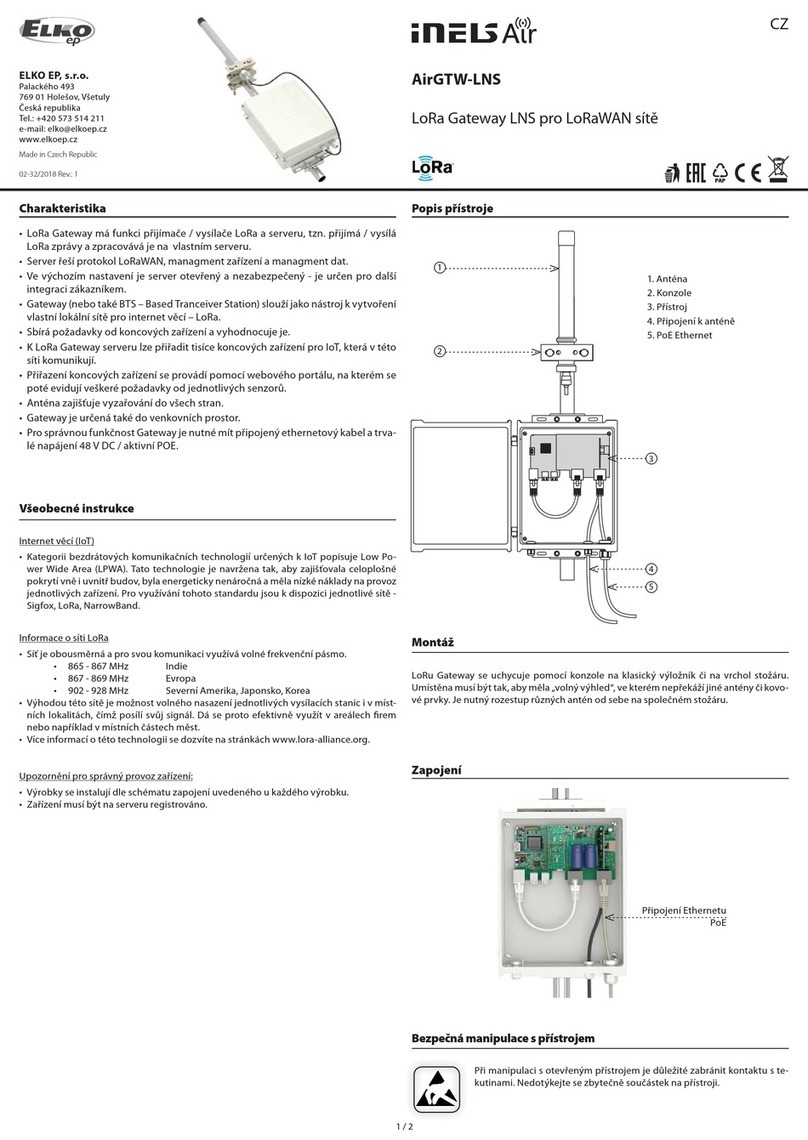
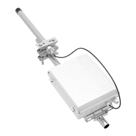
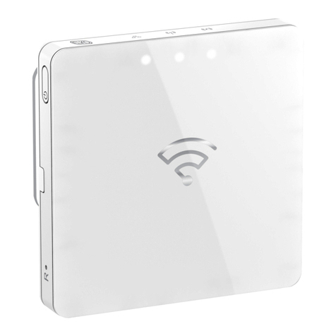
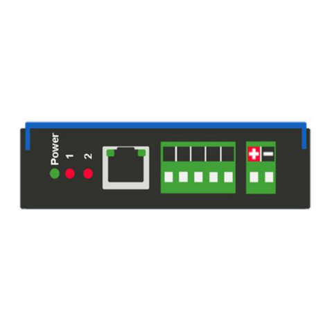
Elko iNELS RFPM-2M User manual

02-5/2018 Rev.0
RFPM-2M
Made in Czech Republic
1/7
60 - 90 % 80 - 95 % 20 - 60 % 0 - 10 % 80- 90 %
☺
☺
☺
☺
☺
RFRP-20
PULS 1 PULS 2
S0+
S0-
TARIF
TARIF
router
1
2
3
4
5
6
7
8
10
11
12
13
9
15
7
14
STORAGE
ELKO EP, s.r.o. | Palackého 493 | 769 01 Holešov, Všetuly | Czech republic | e-mail: [email protected]
EN Support: +420 778 427 366
www.elkoep.com
Energy gateway
EN
Charakteristika
• The energy gateway is a central device for assessing energy consumption (electricity, water, gas).
• • It acts as an interface between the pulse converter RFTM-1 and your smartphone.The Energy
Gateway allows you to connect up to 8 pulse transducers.
• Connection to the data network is made by means of LAN Ethernet connector or wirelessly via a
Wi-Fi network.
• The monitored data is stored inside the unit (it can also be sent to external storage - cloud).
• By means of the application iHC and cloud connection, it is possible to maintain online access to
data and monitoring history.
• Up to 4 tariff meter readings of electricity consumption, which can be displayed in the form of kWh
or financial costs.
• Option of setting reaction to specific consumption to switch the output on or off (RFSA-6x and
CU3).
• The unit enables connecting up to three current transformers CT50 to each other for measuring
electricity.
• Direct connection to iNELS BUS using integrated CIB terminals.
• 3-module design, mounted on a DIN rail into the switchboard.
• The supply includes an internal antenna AN-I, if the unit is installed in a metal switchboard, you can
use the external antenna AN-E to enhance the signal.
• The device supply voltage is provided from monitored phases.
• Range up to 100 m (in open space), if the signal between the controller and the user is weak, use
the signal repeater RFRP-20 or protocol component RFIO2 that support this feature.
• Communication frequency with bidirectional protocol iNELS RF Control.
• In order to communicate with the gateway, it must be connected to the local network using the
RJ45 Ethernet connector or wirelessly over the WiFi network.
• The Energy Gateway stores the measured data directly on the internal memory storage. Online
data and history can be viewed through iHC applications (MAIRF and MIIRF) or cloud connections
on the ELKO Cloud site. The last option is to display the measured values directly on the RFPM-2
web interface.
• Measurement of power consumption can be distinguished by up to four tariffs that can be
displayed in kWh or financial costs.
• Other benefits include the ability to set the response to a specific consumption. An example may
be to switch off or on the RFSA - 6x and CU3 outputs.
• The energy gate takes usually 10 minutes, but not more than 1 hour.
Assembly
mounting into switchboard
Connection
connection to the tariff
(potential free contact)
CAUTION! Do not connect the HDO contact)
Description, Indication
1. Terminals for connection of current
measuring probes
2. Connect Ethernet
3. Storage operation indication
4. WiFi antenna
5. Relay switch indication
6. RESET button:
- Enter the bootloader - turn off the power,
press the button and hold the button> 2s
when the power is on
- Return to factory settings - power off, press
button and hold power button> 10s
7. Voltage and voltage terminals
8. Relay output
9. Supply voltage indication / unit status:
- Lit - STOP status
- Flashes - RUN status
10. Pulse and tariff inputs
11. RF communication indication
12. RF antenna
13. Tariff indication:
- TARIFF 1: red
- TARIFF 2: green
- TARIFF 3: blue
- TARIFF 4: Yellow
14. RF, LAN and WLAN addresses
15. Phase status indication L1, L2, L3:
- Failure (redundancy): red
- Phase active: green
- Unmonitored phase: LED off
Radio frequency signal penetration through various construction materials
brick walls wooden structures
with plaster boards
reinforced
concrete metal partitions common glass

02-5/2018 Rev.0
RFPM-2M
Made in Czech Republic
TARIF 1/2
router
N
16
18
L1
L2
L3
I1
I1*
I2
I2*
I3
I3*
N
L1
L2
L3
max.
F16A / 250 V
RF
00000, 006
RFPM-2MRFTM-1
N
16
18
L1
L2
L3
I1
I1*
I2
I2*
I3
I3*
N
L1
L2
L3
max.
F16A / 250 V
N
16
18
L1
L2
L3
I1
I1*
I2
I2*
I3
I3*
N
L
max.
F16A / 250 V
CT50
CT50
CT50
CT50
2/7
ELKO EP, s.r.o. | Palackého 493 | 769 01 Holešov, Všetuly | Czech republic | e-mail: [email protected]
EN Support: +420 778 427 366
www.elkoep.com
Energy gateway
EN
Tariff
Example of wiring for two-wire connection
TARIF
TARIF 1
TARIF 2
TARIF 3
TARIF 4
Indication
illuminated red LED
illuminated green LED
illuminated blau LED
illuminated yellow LED
Linking
Without wiring
TARIF 1-COM
TARIF 2-COM
TARIF 1-COM, TARIF 2-COM
An example of using the output relay
- phase failure monitoring
- Excessive consumption
- Undercover ....
Contactor
Methods of sensing meters
1-phase wiring 3-phase wiring
Note: The arrow inside the CT50 current transformer must be directed to the appliance.
I1, I2, I3 - red wire
I1*, I2*, I3* - black wire
I1 - red wire
I1* - black wire
• LS - LED sensor
- The LED sensor scans LED impulses on the meter, which indicates consumption by flashing.
- The LED sensor is particularly suitable for power meters that support LED pulse sensing (the LED on the meter is
marked “imp”).
- The sensor‘s scanner is affixed with glue above the LED diode of the meter signaling indication of consumption.
- The sensor is connected to the internal terminal of the RFTM-1 converter.
• MS - Magnetic sensor
- The magnetic sensor scans movement of the numeral, upon which a permanent magnet is placed.
- The MS sensor is particularly suitable for gas meters that support magnetic sensing.
- The device sensor is fastened by gluing over the last number of the dial unit measured (it may be designated on the
silver reflective element number 6).
- The sensor is connected to the internal terminal of the RFTM-1 converter.
• WS - Magnetic sensor water meter
- A magnetic sensor that detects the pulse that is created by each rotation of the magnet placed on the unit dial meter.
- The WS sensor is especially suitable for water meters that support magnetic sensing.
- The sensing sensor is glued over the circular unit face of the gauge (the scanning dial is different from the other
indicators, e.g. the white arrow wheel).
- The sensor is connected to the internal terminal of the RFTM-1 converter.
Note: The standard supplied length of 1.5 m can be custom ordered in an extended version of up to 5 m.
Sensor
•Scanning with sensor (MS / WS / LS) and device RFTM-1
•Scanning with the current transformer CT50

02-5/2018 Rev.0
RFPM-2M
Made in Czech Republic
00000,00
RFPM-2M
S0+ S0 -
RF
00000,00
RFTM-1 RFPM-2M
3/7
ELKO EP, s.r.o. | Palackého 493 | 769 01 Holešov, Všetuly | Czech republic | e-mail: [email protected]
EN Support: +420 778 427 366
www.elkoep.com
Energy gateway
EN
•Scanning with output "S0" and RFTM-1 •Scanning with output "S0"
Impulse output
• S0 - contact, open collector, reed magnetic contact
- Impulse output meters marked "S0" connected to the GND and DATA1 terminals on the RFTM-1 sensor.
- When polarization is indicated on the meter, the terminals S0 + and S0- must be distinguished when
connected to the "S0" impulse output.
Impulse output
Notice
- RFTM-1 / RFPM-2M / sensors (LS, MS, WS) do not affect the consumption meter and do not affect the measurement of the measured quantity.
- Electricity meters, water meters and gas meters are the property of energy suppliers. Without their knowledge and permission, they are not allowed to interfere with internal connections (seals, supply
lines, etc.).
Installation of RFPM-2M
Connect the RFPM-2M to the power supply (can be powered from the monitored phase).
Use an Ethernet cable to connect it to your PC / Router. By default, static IP address 192.168.1.2 is set on RFPM-2M.
If you do not have the same IP range on the router, you need to set the same IP address range in your PC (Control Panel \
Network and Internet \ Network Connections \ Local Area Connection \ Properties \ Version 4 Protocol \ Use the following IP
address \ 192.168.1.10 - to make RFPM-2M available for configuration.
After this, open a web browser. Enter the IP address 192.168.1.2.
The RFPM-2M Web Environment opens, where you can configure your device.
RFPM-2 will require login through your username and password, which are set by default:
Name: admin
Password: admin
Pro úspěšné nastavení času z NTP serveru je nutné RFPM-2 po nastavení jeho sítě restartovat.
Note: Press and hold the RFPM-2 button for 10 seconds on the front panel of the instrument (RESET). The IP address and login
information will return to the factory settings.
Once logged in, you'll see an interface for managing and displaying measured data in your browser.
There are four tabs in the top bar:
Displaying current statuses
Graphical display of measured values
Setting the RFPM-2M
System Settings

02-5/2018 Rev.0
RFPM-2M
Made in Czech Republic
4/7
ELKO EP, s.r.o. | Palackého 493 | 769 01 Holešov, Všetuly | Czech republic | e-mail: [email protected]
EN Support: +420 778 427 366
www.elkoep.com
Energy gateway
EN
Settings - set RFPM-2M
The entire RFPM2-M is divided into several parts:
- Set up a network interface that allows network communication.
- setting of RFTM-1 pulse transducers
- External RFPM-2 inputs and security settings.
Device mode - RFPM-2M can be set as:
• Access Point Bridge – RFPM-2M is an Ethernet cable connected to a home router that assigns IP to all devices that connect
to RFPM-2M.
• Access Point LAN – RFPM-2M creates a custom network that is separate from the home network. Devices can only be
accessed from this network.
• Client LAN – RFPM-2M is connected to a home router using DHCP or static IP. RFPM-2M acts as a terminal device and
cannot be accessed directly through it.
Use DHCP - Network settings
• Yes – IP address is set automatically
• No – IP address needs to be set in the appropriate range of the connected router (filling the IP address of RFPM-2, masks,
gateways and DNS).
WLAN Access Point Settings - WiFi network setup RFPM-2M
• ESSID – the name of WiFi created
• Encryption – type of security
• Password – must be filled in the required form for that security
• Channel – WiFi broadcast channel
LAN Network Address Server Settings (DHCP) - setting assigned ranges of connected devices.
Network interface settings
• Signal – display the RFTM-1 signal strength
• Name – RFTM-1 name optionally chosen
• Address – The RF address that is listed on RFTM-1
• Unit of measurment – Unit of measurement (kW / h - for electricity measurement or m3 - for water or gas measurement)
• Interval minutes – After the set time interval has elapsed, RFTM-1 sends information about the magnitude of the
measured value (minimum interval is 1 minute).
• Treshold (pulse) – the pulse value pulse interval - after recording the set number of pulses RFTM-1 sends information
on the size of the measured value (the minimum number of pulses is 1) - the RFTM-1 can send this information at most
once per minute
• Pulses – Pulse value for the measured value (the value that translates the number of pulses per unit of a given quantity)
- this is given on the meter, gas meter or water meter (e.g.: 800 meters / kWh on the meter).
• Edit / Delete / Add device – buttons to add / edit / delete settings for RFTM-1
Setting the RFTM-1 pulse converter
L1, L2, L3 setup - settings for each phase
Voltage monitoring (overvoltage, under-voltage) - sets the upper level in the range of 138-276V (overvoltage) and the
lower level in the range of 35-99% of the upper level. If the phase moves from this set band, the output relay switches on
/ off the contact (if this function is indicated).
• L1, L2, L3 – Setting for Phase 1, Phase 2, and Phase 3
• –– setting the limit value of the quantities
• HYS – fixed deviation attributed to the limit value when returning to the supervised zone
• WARN – Activating this button activates the Warning function
• RELAY – by activating this button it is possible to switch the relay when the defined value is exceeded
• Over Voltage (V) – overvoltage
• Under Voltage (V) – Under-voltage
• Phase Loss (V) – monitors loss of voltage on individual phases
• THD Voltage (%), THD Current (%) – percentage deviation expressing distortion from ideal harmonic flow.
• Asymmetry (%) – the asymmetry rate between the phases is set at 5-20%. If the set asymmetry is exceeded, the relay
can be switched on / off.

02-5/2018 Rev.0
RFPM-2M
Made in Czech Republic
5/7
ELKO EP, s.r.o. | Palackého 493 | 769 01 Holešov, Všetuly | Czech republic | e-mail: [email protected]
EN Support: +420 778 427 366
www.elkoep.com
Energy gateway
EN
External setup - setting for external inputs
In the first column - external inputs
• Name
• Unit of measurment – measured quantity
• Pulses – number of pulses per unit of measured quantity
External RFPM-2 inputs and security settings
Services - set up a new password and access to iMM
Web interface
• Admin password – set a new password for web access
iMM (iNELS Multimedia)
• Admin password – password for the Administrator account
• User password – the password for the user account
After all the changes you made, you must save the entire settings with the Save button and apply the changes made by
clicking Apply settings.
System - System settings
This tab is primarily used to update the firmware.
The current firmware is available at https://www.elkoep.com/energy-brana-rfpm-2m.
Download the firmware by selecting a file on your computer and upload it to RFPM-2. After the new firmware is loaded, the power
can be retrieved for several minutes.
Bootloader
Serves for FW updates.
Bootloader input - power off, press button, and hold button> 2s when the power is on.
After the FW update, the RFPM-2M will run within 30-60 minutes.

02-5/2018 Rev.0
RFPM-2M
Made in Czech Republic
L1+L2+L3
currentRms0
-
-
-
-
frequency
activePowerT
reactivePowerT
apparentPowerT
powerFactorT
fundamentalPowerT
harmonicPowerT
-
L1
currentRmsL1
voltageRmsL1
asymmetryL1
thdnVoltageL1
thdnCurrentL1
-
activePowerL1
reactivePowerL1
apparentPowerL1
powerFactorL1
fundamentalPowerL1
harmonicPowerL1
L2
currentRmsL2
voltageRmsL2
asymmetryL2
thdnVoltageL2
thdnCurrentL2
-
activePowerL2
reactivePowerL2
apparentPowerL2
powerFactorL2
fundamentalPowerL2
harmonicPowerL2
L3
currentRmsL3
voltageRmsL3
asymmetryL3
thdnVoltageL3
thdnCurrentL3
-
activePowerL3
reactivePowerL3
apparentPowerL3
powerFactorL3
fundamentalPowerL3
harmonicPowerL3
voltageAngleB voltageAngleC
6/7
ELKO EP, s.r.o. | Palackého 493 | 769 01 Holešov, Všetuly | Czech republic | e-mail: [email protected]
EN Support: +420 778 427 366
www.elkoep.com
Energy gateway
EN
Mobile App
Measured data can also be displayed in iHC applications. These are available for both Android and iOS platforms.
• For an Android mobile phone: You download the current version on iGo-MAIRF on Google Play.
https://play.google.com/store/apps/details?id=en.elkoep.ihc_marf_us&hl=en
• For IOS mobile phones: Download the current version of the iHC-MIIRF app store.
https://itunes.apple.com/en/app/inels-home-control-rf-for-iphone/id1189384684?mt=8
For more information about RFPM-2 settings in mobile applications, see the manual of these applications, which can be found on www.elkoep.com or directly in the applications.
View measured data
Actual data - displays current statuses
Phase current
Phase voltage
Asymmetry
Distortion of the sine
wave signal
Distortion sine wave
signal ow
Frequency
Active performance
Reactive power
Apparent performance
Power factor
Power fundamental
harmonic
Performance of other
harmonics
Phase voltageshift
between phases
Graph - graphical display of measured values

02-5/2018 Rev.0
RFPM-2M
Made in Czech Republic
7/7
ELKO EP, s.r.o. | Palackého 493 | 769 01 Holešov, Všetuly | Czech republic | e-mail: [email protected]
EN Support: +420 778 427 366
www.elkoep.com
Energy gateway
EN
230VAC/ 50-60 Hz, 1f / 3f +N
+15/-20%
5VA
140V, +10/-20%
1NO/NCswitches L1
16 A / AC1
4000 VA (AC1)
3 x 10
7
0.7 x 10
5
two-way addressed message, see manuals
RF Touch Compatible
866 MHz, 868 MHz, 916 MHz
two-way addressed message
SMA -FEMALE*
1dB (part of suply)
up to 100 m
WEB/ MobileApplications
Blootloader (stisk >2s) / Unit reset (press >10 s)
AP Bridge/ AP LAN / Client
IEEE 802.11 b/g/n/ 2.4 GHz
WEP, WPA-PSK, WPA2-PSK
RP -SMA -FEMALE*
1dB (part of suply)
up to 20 m
static IP / DHCP Client
10 / 100 Mbit / s
RJ45
192.168.1.2
PULS1(S0), PULS2(S0)
TARF1, TARF2-binary combination
switching by contact/opening by collector
reinforced Insulation
(Cat. II surges by EN 60664-1)
3 x CT-50
RFTM-1
1f-3f
50 -60 Hz/±10 %
Class 1.0
max.50 A (current transformer CT50)
max.16 mm
-20 .. + 35°C
-30.. +70°C
vertical
DIN rail EN60715
IP20 from front panel / IP40in cover
II.
2
max.1x 2.5, max.2x 1.5 / with ahollow max.1.5
90 x 52 x 65 mm
125 g
Technical parameters
Supply/ measured voltage:
Supplyvoltagetolerance:
Closed relay power input:
Switching voltagelevel:
Output RELE
Number of contacts:
Max.current:
Switching power:
Mechanical service life:
Electrical service life:
Relay reaction:
Interface RF Control
Communication protocol:
Broadcasting frequency
Signal transfer method:
Output for antenna:
Antenna RF:
Rangein open space:
Controlling
Controlling:
Button Reset:
Interface Wi-Fi
Wi-Fimode:
Standard:
Wi-FiSecurity:
Frequency rangeWi-Fi:
Antenna Wi-Fi:
Range:
Interface Ethernet
Network settings:
Transfer speed:
Connector:
DefaultIP address / IP address of
bootloader:
Measuring
Pulse inputs:
Tari inputs:
Option of switching inputs:
Separation by isolation of power and
control circuits:
Probes measuring current:
Wireless consumption sensor:
Measuring circuit
Network:
Frequency:
Accuracy:
Current measuring coil:
Wire diameter:
Other data
Working temperature:
Storagetemperature:
Operating position:
Mounting:
Protection:
Overvoltagecategory:
Degree of pollution:
Cross-section of connecting wires (mm2):
Dimension:
Weight:
* Max Tightening Torque for antenna connector is 0.56 Nm.
Attention:
When you instal iNELS RF Control system, you have to keep minimal distance 1 cm between each units.
Between the individual commands must be an interval of at least 1s.
Warning
Instruction manual is designated for mounting and also for user of the device. It is always a part of its
packing. Installation and connection can be carried out only by a person with adequate professional
qualification upon understanding this instruction manual and functions of the device, and while
observing all valid regulations. Trouble-free function of the device also depends on transportation,
storing and handling. In case you notice any sign of damage, deformation, malfunction or missing
part, do not install this device and return it to its seller. It is necessary to treat this product and its
parts as electronic waste after its lifetime is terminated. Before starting installation, make sure that all
wires, connected parts or terminals are de-energized. While mounting and servicing observe safety
regulations, norms, directives and professional, and export regulations for working with electrical
devices. Do not touch parts of the device that are energized – life threat. Due to transmissivity of RF
signal, observe correct location of RF components in a building where the installation is taking place.
RF Control is designated only for mounting in interiors. Devices are not designated for installation
into exteriors and humid spaces. The must not be installed into metal switchboards and into plastic
switchboards with metal door – transmissivity of RF signal is then impossible. RF Control is not
recommended for pulleys etc. – radiofrequency signal can be shielded by an obstruction, interfered,
battery of the transceiver can get flat etc. and thus disable remote control.
Table of contents
Other Elko Gateway manuals
