2400PSUA-4 Quad 2405/2407LTA DC Power Supply
2400PSUA-4 - 4Revision 1.1
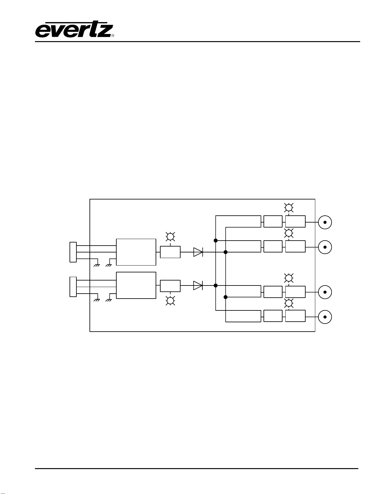
2.1. 2400PSUA-4 CONNECTIONS
AC IN 1+2 100-240VAC, 50/60 Hz, auto-ranging AC inputs. Each input is separately connected to one
of the internal, redundant AC/DC power supplies. The dual connectors permit connection to
independent, redundant AC sources if available.
Two cable assemblies with mating connectors on one and male IEC320 connectors on the
other end are included. The IEC320 connectors permit the use of standard IEC320 line cords
with plug type appropriate for the particular area of the world where the 2400PSUA-4 is to be
used.
!
These cable assemblies are not suitable for exposure to the elements, and are
designed to be used only when the 2400PSUA-4 is to be mounted indoors or inside
of an enclosure.
Also included are two mating connectors, without cable assemblies attached. This permits
customer connection of appropriate cable for hard-wired or other specific applications.
Connections are via solder-cup, using stranded 18 AWG (0.823 mm2) wire. The assembled
connector will provide a waterproof seal.
!
Use properly rated cable for the application and observe local electrical code.
"Maximum cable outside diameter for use with supplied connectors is 0.25”
(6.4mm).
When viewed from the rear of the connector where wiring connections are made (as opposed
to the mating end) wire connections should be made as follows:
Figure 2-3: Power Connector Pinout
UNIT 1-4 Output F-Type connector for DC power connections to 2405/2407LTA’s. Each output features
active short-circuit and overload protection.
"It is recommended that unused outputs be appropriately caped off or taped to
protect them if installed in an environment exposed to the elements.