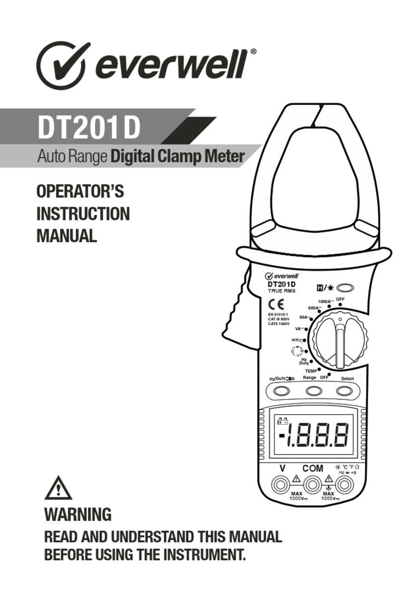
Everwell 266 User manual

INSTRUCTION
MANUAL
266
Digital Clamp Meter
WARNING
READ AND UNDERSTAND THIS MANUAL
BEFORE USING THE INSTRUMENT.

Warning
To avoid possible electric shock or personal injury, and to
avoid possible damage to the meter or to the equipment
under test, adhere to the following rules:
• Before using the meter inspect the case. Do not use the
meter if it is damaged or the case (or part of the case) is
removed. Inspect for cracks or missing plastic pieces. Pay
attention to the insulation around the connectors.
• Inspect the test leads for damaged insulation or exposed
metal. Check the test leads for continuity.
• Do not apply more than the rated voltage, as marked on the
meter, between the terminals or between any terminal and
grounding.
• The rotary switch should be placed in the right position and
no changeover of range shall be made during measurement
to prevent damage of the meter.
• When the meter is working at an effective voltage over 60V
in DC or 36V rms in AC, special care should be taken for
there is danger of electric shock.
• Use the proper terminals, function, and range for your
measurements.
• Do not use or store the meter in an environment of high
temperature, humidity, explosive, inflammable and strong
magnetic field. The performance of the meter may
deteriorate after dampened.
• When using the test leads, keep your fingers behind the
finger guards.
• Disconnect circuit power and discharge all high-voltage
capacitors before testing resistance, continuity or diodes.
• Replace the battery as soon as the battery indicator
appears. With a low battery, the meter might produce false
readings that can lead to electric shock and personal injury.
-2-

Warning
To avoid possible electric shock or personal injury, and to
avoid possible damage to the meter or to the equipment
under test, adhere to the following rules:
• Before using the meter inspect the case. Do not use the
meter if it is damaged or the case (or part of the case) is
removed. Inspect for cracks or missing plastic pieces. Pay
attention to the insulation around the connectors.
• Inspect the test leads for damaged insulation or exposed
metal. Check the test leads for continuity.
• Do not apply more than the rated voltage, as marked on the
meter, between the terminals or between any terminal and
grounding.
• The rotary switch should be placed in the right position and
no changeover of range shall be made during measurement
to prevent damage of the meter.
• When the meter is working at an effective voltage over 60V
in DC or 36V rms in AC, special care should be taken for
there is danger of electric shock.
• Use the proper terminals, function, and range for your
measurements.
• Do not use or store the meter in an environment of high
temperature, humidity, explosive, inflammable and strong
magnetic field. The performance of the meter may
deteriorate after dampened.
• When using the test leads, keep your fingers behind the
finger guards.
• Disconnect circuit power and discharge all high-voltage
capacitors before testing resistance, continuity or diodes.
• Replace the battery as soon as the battery indicator
appears. With a low battery, the meter might produce false
readings that can lead to electric shock and personal injury.
• Remove the connection between the testing leads and the
circuit being tested, and turn the meter power off before
opening the Meter case.
• When servicing the meter, use only the same model
number or identical electrical specifications replacement
parts.
• The internal circuit of the meter shall not be altered at will to
avoid damage of the meter and any accident.
• Soft cloth and mild detergent should be used to clean the
surface of the meter when servicing. No abrasive and
solvent should be used to prevent the surface of the meter
from corrosion, damage and accident.
• The meter is suitable for indoor use.
• Turn the meter power off when it is not in use and take out
the battery when not using for a long time. Constantly check
the battery as it may leak when it has been using for some
time, replace the battery as soon as leaking appears.
-3-

-4-

➀Transformer Jaws
Pick up the AC Current flowing through the conductor
➁Trigger
Press the level to open the transformer jaws when the finger
press on the level is released the jaws will close again.
➂Data Hold Switch
A push switch (pushes on, push off, do not pull to select
function). All function and ranges with this feature.
➃Rotary Switch
A rotary switch is used to select measurement Function and
Range switch.
➄Display
3 ½ digits (1999 counts), decimal point, minus polarity, Over
range and “ ” indicators.
➅EXT Input Connect
Used for accept insulation tester unit EXT banana plugs,
when measurement insulation resistance.
➆COM Input Connect
Low input for all voltage, resistance, and continuity
measurement will accept banana plugs. When
measurement insulation resistance, used for accept
insulation tester unit COM banana plugs.
➇ VΩ Input Connect
High input for all voltage, resistance, and continuity
measurement will accept banana plugs. When
measurement insulation resistance, used for accept
insulation tester unit VΩ banana plugs.
➈Drop-Proof Wrist Strap
Prevents the instrument from slipping off the hand while in
use.
-5-

1. GENERAL SPECIFICATIONS
•Max display: LCD 3 ½ digits, 1999 counts, 0.5” high
•Polarity: Automatic, indicated minus, assumed plus.
•Measure method: double integral A/D switch implement
•Sampling speed: 2 times per second
•Over-load indication: “1” is displayed
•Operating Environment: 0°C~40°C, at <80%RH
•Storage Environment: -10°C~50°C, at <85%RH
•Power: 9V NEDA 1604 or 6F22
•Low battery indication: “ ”
•Static electricity: about 4mA
•Product Size: 230×68×37mm
•Product net weight: 240g (including battery)
2. TECHNICAL SPECIFICATIONS
Accuracies are guaranteed for 1 year, 23°C±5°C, less than
80%RH
2-1. DC Voltage
Overload Protection: 1000V DC or 750V rms for all ranges.
2-2. Audible Continuity
Overload Protection: 15 second maximum 220V rms.
-6-
2-3. AC Voltage
RESPONSE: Average responding, calibrated in rms of a sine
wave.
FREQUENCY RANGE: 45Hz ~ 450Hz
OVERLOAD PROTECTION: 1000V DC or 750V rms for all
ranges.
2-4. AC Current (Average sensing, calibrated to rms of
sine wave)
Overload Protection: 1200A within 60 seconds. Jaw
Opening: 2.09” (53mm)
2-5. Insulation Test (With option 500V insulation tester
unit)
Range Resolution Accuracy
1000V 1V ±(1.0% of rdg + 5D)
Range Description
Built-in buzzer sounds if resistance
is less than 30±20Ω

1. GENERAL SPECIFICATIONS
•Max display: LCD 3 ½ digits, 1999 counts, 0.5” high
•Polarity: Automatic, indicated minus, assumed plus.
•Measure method: double integral A/D switch implement
•Sampling speed: 2 times per second
•Over-load indication: “1” is displayed
•Operating Environment: 0°C~40°C, at <80%RH
•Storage Environment: -10°C~50°C, at <85%RH
•Power: 9V NEDA 1604 or 6F22
•Low battery indication: “ ”
•Static electricity: about 4mA
•Product Size: 230×68×37mm
•Product net weight: 240g (including battery)
2. TECHNICAL SPECIFICATIONS
Accuracies are guaranteed for 1 year, 23°C±5°C, less than
80%RH
2-1. DC Voltage
Overload Protection: 1000V DC or 750V rms for all ranges.
2-2. Audible Continuity
Overload Protection: 15 second maximum 220V rms.
-7-
2-3. AC Voltage
RESPONSE: Average responding, calibrated in rms of a sine
wave.
FREQUENCY RANGE: 45Hz ~ 450Hz
OVERLOAD PROTECTION: 1000V DC or 750V rms for all
ranges.
2-4. AC Current (Average sensing, calibrated to rms of
sine wave)
Overload Protection: 1200A within 60 seconds. Jaw
Opening: 2.09” (53mm)
2-5. Insulation Test (With option 500V insulation tester
unit)
Range Resolution Accuracy
750V 1V ±(1.2% of rdg + 5D)
Range
200A 100mA
±(2.5% + 8)
for 800A and below
±(2.5% + 13)
The reading is only for reference
for more than 800A
Resolution Accuracy(50Hz ~ 60Hz)
1A
1000A
Range
20MΩ 10KΩ
±(4% + 2)
for 500Ω and below
±(2% + 2)
±(5% + 2)
for others
Resolution Accuracy(50Hz ~ 60Hz)
1MΩ
2000MΩ

-8-
2-6. Resistance
Maximum Open Circuit Voltage: 3V.
Overload Protection: 15 seconds maximum 220Vrms.
3. OPERATING INSTRUCTIONS
3-1. AC Current Measure
1. Make sure that “Data Hold” Switch is not pressed.
2. Set Range Switch to the ACA 1000A range. If the display
indicates one or more leading zeros. Shift to the 200A range
to improve the resolution of the measurement.
3. Press the trigger to open the transformer jaws
and clamp one conductor only it is impossible to make
measurements when two or three conductors are clamped at
the same time.
4. Display reading is flow the conductorAC current.
3-2. Insulation Resistance Tester
1. Set Range Switch to the insulation tester 2000MΩ range.
This condition the display value is unstable that is normal.
2. The insulation tester unit VΩ-COM-EXT three banana
plugs insert to clamp meter VΩ-COM-EXT three input
connector.
3. Set the insulation tester unit range switch to the 2000MΩ
position.
4. Use the insulation tester unit of the test leads.
5. Set the insulation tester power switch to the ON position.
6. Depress the PUSH 500V push-push switch, the 500V on
red LED lamp will light. Clamp meter display reading is the
insulation resistance value if the reading is below 19MΩ,
change clamp meter and insulation tester unit to 20MΩ
range, can be increase the accuracy.
7. If the insulation tester unit is not use the power switch
must shift to power OFF position, and the test leads must
leave the E-L input connect, that can be increase battery life
and prevent electrical shock hazard.
3-3. DC & AC Voltage Measurement
1. Connect red test lead to “VΩ” jack, Black lead to “COM” jack.
2. Set RANGE switch to desired VOLTAGE position, if the
voltage to be measured is not known beforehand, set switch
to the highest range and reduce it until satisfactory reading is
obtained.
3. Connect test leads to device or circuit being measured.
4. Turn on power of the device or circuit being measured
voltage value will appear on Digital Display along with the
voltage polarity.
3-4. Resistance Measurement
1. Red lead to “VΩ”. Black lead to “COM”.
2. RANGE switch to desired Ω position.
3. If the resistance being measured is connected to a circuit,
turn off power and discharge all capacitors before
measurement.
4. Connect test leads to circuit being measured.
5. Read resistance value on Digital Display.
3-5. Audible Continuity Test
1. Red lead to “VΩ”,Black lead to “COM”.
2. RANGE switch to “ ” position.
3. Connect test leads to two points of circuit to be
tested. If the resistance is lower then 30Ω±20Ω, the buzzer
will sound.
4. BATTERY REPLACEMENT
If “ ” appears in display, it indicates that the battery should
be replaced.
5. ACCESSORIES
• Operator’s instruction manual
• Set of test leads
• Gift box
• 9-volt battery, NEDA 1604 6F22 type.
Range Resolution Accuracy
200Ω 0.1Ω ±(1.0% of rdg + 10D)
20KΩ 10Ω ±(1.0% of rdg + 4D)

-9-
2-6. Resistance
Maximum Open Circuit Voltage: 3V.
Overload Protection: 15 seconds maximum 220Vrms.
3. OPERATING INSTRUCTIONS
3-1. AC Current Measure
1. Make sure that “Data Hold” Switch is not pressed.
2. Set Range Switch to the ACA 1000A range. If the display
indicates one or more leading zeros. Shift to the 200A range
to improve the resolution of the measurement.
3. Press the trigger to open the transformer jaws
and clamp one conductor only it is impossible to make
measurements when two or three conductors are clamped at
the same time.
4. Display reading is flow the conductorAC current.
3-2. Insulation Resistance Tester
1. Set Range Switch to the insulation tester 2000MΩ range.
This condition the display value is unstable that is normal.
2. The insulation tester unit VΩ-COM-EXT three banana
plugs insert to clamp meter VΩ-COM-EXT three input
connector.
3. Set the insulation tester unit range switch to the 2000MΩ
position.
4. Use the insulation tester unit of the test leads.
5. Set the insulation tester power switch to the ON position.
6. Depress the PUSH 500V push-push switch, the 500V on
red LED lamp will light. Clamp meter display reading is the
insulation resistance value if the reading is below 19MΩ,
change clamp meter and insulation tester unit to 20MΩ
range, can be increase the accuracy.
7. If the insulation tester unit is not use the power switch
must shift to power OFF position, and the test leads must
leave the E-L input connect, that can be increase battery life
and prevent electrical shock hazard.
3-3. DC & AC Voltage Measurement
1. Connect red test lead to “VΩ” jack, Black lead to “COM” jack.
2. Set RANGE switch to desired VOLTAGE position, if the
voltage to be measured is not known beforehand, set switch
to the highest range and reduce it until satisfactory reading is
obtained.
3. Connect test leads to device or circuit being measured.
4. Turn on power of the device or circuit being measured
voltage value will appear on Digital Display along with the
voltage polarity.
3-4. Resistance Measurement
1. Red lead to “VΩ”. Black lead to “COM”.
2. RANGE switch to desired Ω position.
3. If the resistance being measured is connected to a circuit,
turn off power and discharge all capacitors before
measurement.
4. Connect test leads to circuit being measured.
5. Read resistance value on Digital Display.
3-5. Audible Continuity Test
1. Red lead to “VΩ”,Black lead to “COM”.
2. RANGE switch to “ ” position.
3. Connect test leads to two points of circuit to be
tested. If the resistance is lower then 30Ω±20Ω, the buzzer
will sound.
4. BATTERY REPLACEMENT
If “ ” appears in display, it indicates that the battery should
be replaced.
5. ACCESSORIES
• Operator’s instruction manual
• Set of test leads
• Gift box
• 9-volt battery, NEDA 1604 6F22 type.

-10-
2-6. Resistance
Maximum Open Circuit Voltage: 3V.
Overload Protection: 15 seconds maximum 220Vrms.
3. OPERATING INSTRUCTIONS
3-1. AC Current Measure
1. Make sure that “Data Hold” Switch is not pressed.
2. Set Range Switch to the ACA 1000A range. If the display
indicates one or more leading zeros. Shift to the 200A range
to improve the resolution of the measurement.
3. Press the trigger to open the transformer jaws
and clamp one conductor only it is impossible to make
measurements when two or three conductors are clamped at
the same time.
4. Display reading is flow the conductorAC current.
3-2. Insulation Resistance Tester
1. Set Range Switch to the insulation tester 2000MΩ range.
This condition the display value is unstable that is normal.
2. The insulation tester unit VΩ-COM-EXT three banana
plugs insert to clamp meter VΩ-COM-EXT three input
connector.
3. Set the insulation tester unit range switch to the 2000MΩ
position.
4. Use the insulation tester unit of the test leads.
5. Set the insulation tester power switch to the ON position.
6. Depress the PUSH 500V push-push switch, the 500V on
red LED lamp will light. Clamp meter display reading is the
insulation resistance value if the reading is below 19MΩ,
change clamp meter and insulation tester unit to 20MΩ
range, can be increase the accuracy.
7. If the insulation tester unit is not use the power switch
must shift to power OFF position, and the test leads must
leave the E-L input connect, that can be increase battery life
and prevent electrical shock hazard.
3-3. DC & AC Voltage Measurement
1. Connect red test lead to “VΩ” jack, Black lead to “COM” jack.
2. Set RANGE switch to desired VOLTAGE position, if the
voltage to be measured is not known beforehand, set switch
to the highest range and reduce it until satisfactory reading is
obtained.
3. Connect test leads to device or circuit being measured.
4. Turn on power of the device or circuit being measured
voltage value will appear on Digital Display along with the
voltage polarity.
3-4. Resistance Measurement
1. Red lead to “VΩ”. Black lead to “COM”.
2. RANGE switch to desired Ω position.
3. If the resistance being measured is connected to a circuit,
turn off power and discharge all capacitors before
measurement.
4. Connect test leads to circuit being measured.
5. Read resistance value on Digital Display.
3-5. Audible Continuity Test
1. Red lead to “VΩ”,Black lead to “COM”.
2. RANGE switch to “ ” position.
3. Connect test leads to two points of circuit to be
tested. If the resistance is lower then 30Ω±20Ω, the buzzer
will sound.
4. BATTERY REPLACEMENT
If “ ” appears in display, it indicates that the battery should
be replaced.
5. ACCESSORIES
• Operator’s instruction manual
• Set of test leads
• Gift box
• 9-volt battery, NEDA 1604 6F22 type.

This Instrument is warranted to be free from defects in
material and workmanship for a period of one year.
Any instrument found defective within one year from
the delivery date and returned to the factory with
transportation charges prepaid, will be repaired,
adjusted, or replaced at no charge to the original
purchaser. This warranty does not cover expandable
items such as batteries & fuses. If the defect has been
caused by a misuse or abnormal operating conditions,
the repair will be billed at a nominal cost.
WARRANTY
-11-

www.everwellparts.com
Phone: +1 (305) 406-2331
Fax: +1 (305) 406-2338
Email: [email protected]
10914 NW 33rd St, Miami, FL 33172
Table of contents
Other Everwell Measuring Instrument manuals
Popular Measuring Instrument manuals by other brands

Thermo Scientific
Thermo Scientific Nicolet Summit user guide
Elenco Electronics
Elenco Electronics TT-400K Assembly and instruction manual
Fowler
Fowler mini-Mag Protractor Operating instructions and parts manual
ATP Electronics
ATP Electronics LX-1301 instruction manual
toscano
toscano T-500 user manual

IFM Electronic
IFM Electronic efector 200 OJ50 Series operating instructions
