Young 27106 User manual

PROPELLER ANEMOMETER
MODEL 27106
METEOROLOGICAL INSTRUMENTS
INSTRUCTIONS
R.M. YOUNG COMPANY 2801 AERO PARK DRIVE, TRAVERSE CITY, MICHIGAN 49686, USA
TEL: (231) 946-3980 FAX: (231) 946-4772 WEB: www.youngusa.com
PN: 27106-90
REV: G062819

Page 1
27106-90(G)
MODEL 27106
GILL PROPELLER ANEMOMETER
INTRODUCTION
The Gill Propeller Anemometer is a low threshold precision air
velocity sensor employing a fast response helicoid propeller. The
instrument uses a high quality tach-generator transducer which
converts propeller rotation to a DC voltage that is linearly proportional
to air velocity. The output signal is suitable for a wide range of signal
translators and data logging devices.
Airow from any direction may be measured, however, the propeller
responds only to the component of the air ow which is parallel to the
axis of its rotation. Off-axis response closely approximates a cosine
curve (see accompanying graphs) with appropriate polarity. With
perpendicular air ow the propeller does not rotate.
For detailed studies of low air speeds, optional propeller shaft
extensions improve response in the 90° stall region by improving
symmetry and reducing the stall angle.
The instrument mounts to 3/4 inch standard pipe. A rugged cable
connector provides both electrical and mechanical connection. A
dust cap is provided to protect the connector when the instrument
is removed.
INITIAL CHECKOUT
When the instrument is unpacked it should be carefully checked
for any signs of shipping damage. The propeller shaft should rotate
easily without friction.
Using the WIRING DIAGRAM as a guide, connect the instrument
to an oscilloscope or frequency meter and check for proper signals
from the sensor. The calibration may be checked using the methods
outlined in the CALIBRATION section of this manual.
INSTALLATION
Generally, the instrument should be oriented with the propeller
facing the predominant ow of air being measured. In some
cases it is appropriate to orient the instrument so the predominant
air ow is perpendicular to the propeller such as in applications
measuring the vertical component of wind. Keep in mind that off-axis
response increases the effective threshold and distance constant.
For vertical measurements mount the instrument so the propeller
faces upward. This helps prevent moisture or dirt from entering
around the propeller hub and potentially contaminating the bearings.
If the instrument is used to measure high air velocity or left for extended
periods without attention, tape the threaded cable connector collar
to eliminate the possibility of loosening from vibration. The threaded
joint between the generator and shaft housings may also be taped.
For some applications commutator ripple from the tach-generator
may need to be reduced. Use a 500 uF 10 VDC non-polarized
capacitor connected across the sensor leads as shown in the wiring
diagram. Given the low internal resistance of the tach-generator
the effective time constant of this lter is approximately 15 mS and
will not degrade measurement accuracy to any signicant degree.
The instrument measures both forward and reverse air ow. Signal
polarity relative to the connection pins is shown in the wiring
diagram. In applications measuring horizontal air ow, most users
connect the sensor to produce a positive signal with flow from
the front (counterclockwise propeller rotation). In applications
measuring vertical air flow, the sensor is usually connected so
downdrafts produce a negative signal, updrafts a positive signal.
Output from the tach-generator should be connected to a load
impedance of 10k ohms or higher.
SPECIFICATION SUMMARY
Range, Axial Flow: 0 to 30 m/s (70 mph)
Range, All Angles: 0 to 25 m/s (55 mph)
Propeller: Ø 22cm 4-blade Expanded Polystyrene
(EPS) helicoid propeller
Pitch: 29.4 cm air passage per revolution
Distance Constant*: 1.0 m (3.2 ft.) for 63% recovery
Threshold Sensitivity*: 0.3 m/s (0.6 mph)
Signal Output: Analog DC voltage proportional
to axial wind component. Polarity
reverses with reverse rotation.
1800 rpm (500 mV) =8.8 m/s (19.7 mph)
Power Requirement: Anemometer is self powered
( *Threshold and Distance Constant values are for axial ow.)
GENERAL
Operating Temp: -50 to 50°C (-58 to 122°F)
Specications represent nominal values determined in accordance
with ASTM standard procedures.

Page 2
27106-90(G)
CALIBRATION
Calibration is determined by propeller pitch and the output
characteristics of the tach-generator.
The Model 08274 Expanded Polystyrene (EPS) Propeller has a
29.4 cm/rev pitch. This is equivalent to 0.0049 m/s per rpm and
is accurate to ±1%. Zero offset is insignicant. Formulas for other
units of measurement appear on the calibration chart included with
this manual.
The tach-generator output is set at the factory for 500 ±2 mV at
1800 rpm. Check the output by removing the propeller from the
anemometer and coupling an Anemometer Drive to the shaft. Check
linearity by taking measurements at several different speeds. If
the tach-generator is out of calibration it must be replaced. See
the following MAINTENANCE section for details on replacement
procedure.
Information on checking bearing and transducer torque, which
can affect propeller threshold, also appear in the MAINTENANCE
section.
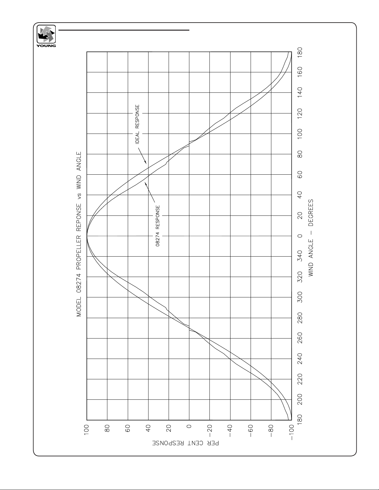
When the propeller is used for measuring vertical wind component,
users may want to apply a 1.25 multiplier to the output signal.
This may be done numerically in data processing operations or
electronically in the signal conditioning. Using the multiplier brings
the anemometer output signal within ±3% of the cosine response for
elevation angles between -30 and +30 degrees. Since the standard
deviation of wind elevation angle in open terrain rarely exceeds
12 degrees, 98% (2.5 standard deviations) of observations will be
within ±30 degrees. Using the multiplier is NOT necessary when the
anemometer is used in a UVW conguration with YOUNG Model
26800 Programmable Translator.
MAINTENANCE
Given proper care the Gill Propeller Anemometer should provide
years of service. Components are conservatively rated and require
little maintenance. The only parts likely to need replacement due to
normal wear are the precision ball bearings and the tach-generator.
The replacement procedures are best performed in a service
facility and only by qualied technicians. If service facilities are not
available return the instrument to the factory.
Refer to the accompanying drawings to become familiar with part
names and locations.
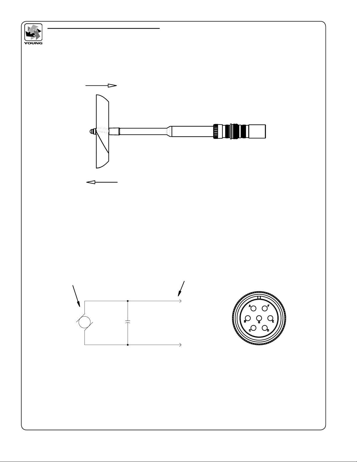
PROPELLER
The Model 08274 Expanded Polystyrene (EPS) Propeller can be
easily damaged by careless handling, high winds, hail, or birds.
Damage from these causes is not covered by warranty. If the
EPS propeller is repeatedly damaged, consider using the more
durable though slightly less sensitive Model 08254 Carbon Fiber
Thermoplastic (CFT) Propeller.
FLANGE BEARING REPLACEMENT
If anemometer bearings become noisy or wind speed threshold
increases above an acceptable level, bearings may need replace-
ment. Check bearing condition using a Model 18310 Anemometer
Bearing Torque Disk. If, after replacing bearings, the torque is still
too high, check the tach-generator for any misalignment.
Replace bearings as follows:
1. REMOVE OLD BEARINGS
a) Remove propeller from anemometer.
b) Unthread and separate shaft housing assembly from
generator housing.
c) Loosen set screw on shaft collar/coupling disk and remove
from propeller shaft.
d) Slide propeller shaft through both bearings and out of
housing.
e) Pull front bearing dust shield off housing.
f) Using the edge of a pocket knife, gently pry front and rear
bearings out of housing.
2. INSTALL NEW BEARINGS
a) Gently insert front bearing into housing.
b) Push front bearing dust shield back onto housing.
c) Carefully slide propeller shaft through front bearing and into
housing.
d) Slide rear bearing over propeller shaft and gently push it into
housing.
e) Place shaft collar/coupling disk on propeller shaft.
f) Allow 0.010 inch (0.25 mm) end play gap between shaft
collar/coupling disk and bearing. Tighten set screw (80 oz
in, 5600 gm-cm max torque).
9) Thread shaft housing assembly into generator housing.
Tighten rmly.
h) Check bearing torque to conrm it is within specications.
TACH-GENERATOR REPLACEMENT
When the tach-generator output becomes erratic (usually due
to brush failure) or begins to show signs of bearing failure (high
torque), the entire generator assembly should be removed and
replaced. If replacing the tach-generator due to excessive torque
make certain it is indeed caused by a worn tach-generator, not the
anemometer ange bearings.
Replace the tach-generator as follows:
1. REMOVE OLD GENERATOR ASSEMBLY
a) Remove propeller from anemometer.
b) Unthread generator housing collar. Pull generator housing
away from sensor connector and generator assembly.
c) Note position of generator wires on sensor connector
pins. Unsolder wires from pins and remove old generator
assembly.
2. INSTALL NEW GENERATOR ASSEMBLY
a) Solder wires from new generator assembly onto proper
sensor connector pins. Verify correct polarity: CCW rotation
produces negative output voltage.
b) Slide generator housing over generator assembly. Firmly
tighten housing collar onto connector threads.
c) Check bearing torque to conrm it is within specication.

Page 3
27106-90(G)
WARRANTY
This product is warranted to be free of defects in materials and
construction for a period of 12 months from date of initial purchase.
Liability is limited to repair or replacement of defective item. A copy
of the warranty policy may be obtained from R. M. Young Company.
CE COMPLIANCE
This product has been tested and shown to comply with European
CE requirements for the EMC Directive. Please note that shielded
cable must be used.
ADDITIONAL REFERENCES
References containing additional information about the Gill Propel-
ler Anemometer are listed below in chronological order:
Holmes, R. M., Gill, G. C., and Carson, H. W., “A Propeller Type
Vertical Anemometer”, Journal of Applied Meteorology,
Vol 3, 1964, pp. 802-804.
Drinkow, R., “A Solution to the Paired Gill-Anemometer Response
Function”, Journal of Applied Meteorology, Vol 11, 1972,
pp. 7-80.
Hicks, B. B., “Propeller Anemometers as Sensors of Atmospheric
Turbulence”, Boundary-Layer Meteorology, Vol 3,1972,
pp. 214-228.
Fichtl, G. H., and Kumar, P., “The Response of Propeller Anemometer
to Turbulent Flow with the Mean Wind Vector Perpendicular to
the Axis of Rotation”, Boundary-Layer Meteorol ogy, Vol 6,1974,
pp. 363-379.
McMichael, J. M., and Klebanoff, P. S., “The Dynamic
Response of Helicoid Anemometers”, NBSIR 75-772,
National Bureau of Standards, 1975.

Page 4
27106-90(G)
PROPELLER CALIBRATION TABLE
08274 PROPELLER

Page 5
27106-90(G)
PROPELLER RESPONSE - WIND ANGLE
OFF AXIS RESPONSE DATA 08274 PROPELLER

Page 6
27106-90(G)
27106 CABLE CONNECTOR WIRING
TACH-GENERATOR POLARITY SHOWN FOR
WIND FLOW DIRECTION.
GENERATOR OUTPUT: 500 mV AT 1800 rpm
ARMATURE RESISTANCE: 32 OHMS
+
-
CABLE CONNECTOR / MOUNT
(PIN DESIGNATIONS)
6.3 V
470 uF
NON-POLARIZED
-
+
B
A
TACH-GENERATOR
CABLE CONNECTOR
R. M. YOUNG COMPANY
2801 Aero-Park Drive , Traverse City, Michigan 49686 U.S.A.
TEL (231) 946-3980 FAX (231) 946-4772
MODEL 27106 PROPELLER ANEMOMETER
WIRING INFORMATION
DWG: W27106(E)
REV: E021318
DRW: JMT
DATE: 02/13/18
CHK:

Page 7
27106-90(G)
08274 22cm X 30cm
EXPANDED POLYSTYRENE (EPS)
27124 SHAFT HOUSING
27111A PROPELLER NUT
27122 FLANGE BEARINGS (2)
27113A DUST SHIELD
27126 O-RING
27153A HOUSING THREADED COLLAR
27159A DUST CAP
27155 SENSOR CONNECTOR (MS 3106A-20-15P
27156A MOUNTING FITTING ASSY (3/4" PIPE)
WITH (MS-3101A-20-15S) RECEPTACLE
27130B HOUSING
27131B SHAFT COLLAR AND COUPLING DISK
27120C PROPELLER SHAFT
27150B D.C. GENERATOR ASSEMBLY
(500mV WITH COUPLING AND CELL)
R. M. YOUNG COMPANY
2801 Aero-Park Drive , Traverse City, Michigan 49686 U.S.A.
TEL (231) 946-3980 FAX (231) 946-4772
MODEL 27106
MANUAL REPLACEMENT PARTS DRAWING
DWG: E05106-90(B)
REV: B062819
DRW: JMT
DATE: 02/13/18
CHK:
27106 GENERAL ASSEMBLY & REPLACEMENT PARTS
Table of contents
Other Young Measuring Instrument manuals

Young
Young Wind Sentry 03002V User manual

Young
Young Wind Sentry Series User manual

Young
Young 06201 User manual

Young
Young ResponseONE 91000 User manual

Young
Young 09101 User manual

Young
Young 27106T User manual

Young
Young 81000 Reference manual

Young
Young 86000-SDI User manual

Young
Young 86004 User manual

Young
Young 86004-SDI User manual
Popular Measuring Instrument manuals by other brands

Siemens
Siemens Sitrans F Series quick start

PCB Piezotronics
PCB Piezotronics IMI Sensors 602D11 Installation and operating manual

Santacary
Santacary iU2-C user manual

PCB Piezotronics
PCB Piezotronics Shear ICP M350B01 Installation and operating manual

Kyoto
Kyoto DA-650 Operation manual

Beckman Coulter
Beckman Coulter LH 780 Instructions for use