Everwin PN70CL User manual
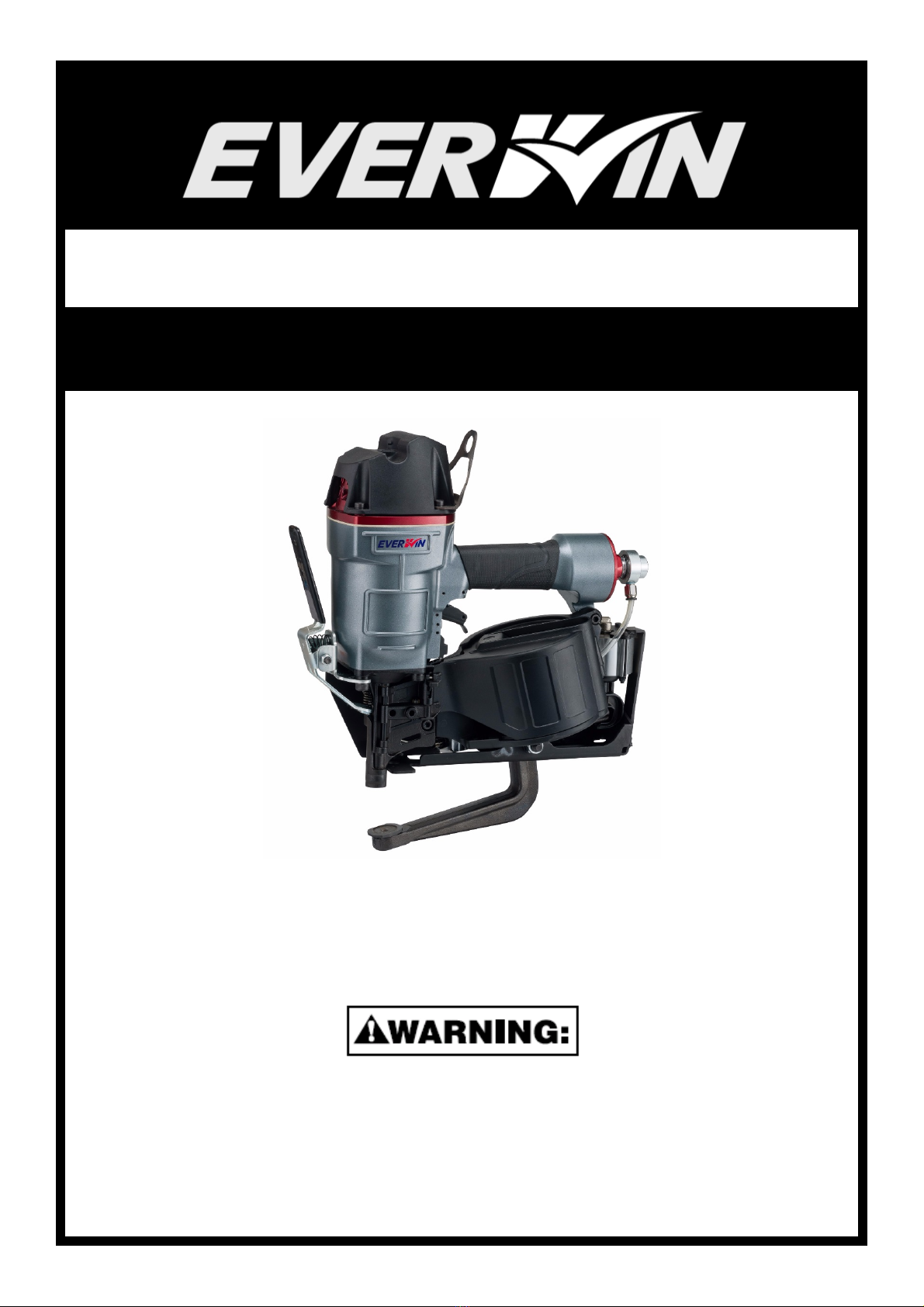
PN70CL
Pneumatic Industrial Clinch Nailer
OPERATIONS and MAINTENANCE MANUAL
CE DECLARATION OF CONFORMITY
20’/05/06
Everwin Pneumatic Corp.
BEFORE OPERATING THIS TOOL, ALL OPERATORS SHOULD READ AND STUDY
THIS MANUAL TO UNDERSTAND AND FOLLOW THE SAFETY WARNINGS AND
INSTRUCTIONS. KEEP THESE INSTRUCTIONS WITH THE TOOL FOR FUTURE
REFERENCE.
105380

2
INTRODUCTION
The tool is
designed for high speed, high volume nailing. These tools will deliver efficient,
dependable service when used correctly and with care. As with any fine power tool, the
manufacturer’s instructions must be followed for best performance. Please study this manual
before operating the tool and understand the safety warnings and cautions. The instructions on
installation, operation and maintenance should be read carefully, and the manuals kept for
reference. NOTE: Additional safety measures may be required because of your particular
application of the tool. Contact your EVERWIN representative or distributor with any questions
concerning the tool and its use. Everwin Pneumatic Corp., Taichung City, Taiwan 41353.
INDEX
1-Year Limited Warranty ----------------------------------------------------------------------------------------------------------- 3
CE Declaration of Conformity --------------------------------------------------------------------------------------------------- 4
Safety Instructions ------------------------------------------------------------------------------------------------------------------ 5
Specifications ------------------------------------------------------------------------------------------------------------------------ 6
Technical Data ----------------------------------------------------------------------------------------------------------------------- 6
Operating Pressure, Setting Correct Pressure ---------------------------------------------------------------------------- 6
Operation ------------------------------------------------------------------------------------------------------------------------------- 7
Air Supply and Connections: Fittings, Hoses, Filters,
Air Consumption, Regulators, Supply source------------------------------------------------------------------------------ 8
Lubrication ----------------------------------------------------------------------------------------------------------------------------- 8
Fastener Loading --------------------------------------------------------------------------------------------------------------------- 9
Tool Operation ------------------------------------------------------------------------------------------------------------------------ 10
Tool Operation Check --------------------------------------------------------------------------------------------------------- ------ 11
Maintaining the Pneumatic Tool ------------------------------------------------------------------------------------------- ------ 12
Driver Maintenance Instructions ------------------------------------------------------------------------------------------------ 12
Trouble Shooting / Repairs -------------------------------------------------------------------------------------------------------- 12

3
1-YEAR LIMITED WARRANTY
(U.S. and Canada Only)
EVERWIN products are designed and manufactured to the highest standards of both material and workmanship.
EVERWIN warrants to the original retail purchaser that the product purchased is free from defect in material and
workmanship and agrees to repair or replace at EVERWIN ‘s option any defective EVERWIN pneumatic stapler or nailer
for a period of one year, subject to the exclusions and limitations described hereunder. To honor a warranty claim,
EVERWIN and its authorized distributor need proof of purchase, may request the damaged tool, serial number of the
damaged tool, photos/videos of the defect for test and evaluation to determine whether the damaged tool is within
warranty conditions; your cooperation in this regard will be appreciated to expedite the claim process and to help with
EVERWIN’s continuous efforts in quality improvement.
THIS WARRANTY IS IN LIEU OF ALL OTHER WARRANTIES, EXPRESS OR IMPLIED, INCLUDING BUT NOT
LIMITED TO THE IMPLIED WARRANTIES OF MERCHANTABILITY OR FITNESS FOR A PARTICULAR PURPOSE.
EVERWIN SHALL NOT BE LIABLE FOR ANY INCIDENTAL OR CONSEQUENTIAL DAMAGES.
WARRANTY EXCLUSIONS
The following warranty exclusions apply:
a. Normal wear parts are not covered by this warranty. Examples of such parts include, o-rings and seals, driver
blades, bumpers, pistons and piston rings.
b. Failure due to normal wear, neglect, abuse, misuse, misapplication, accidents, over-pressure usage, improper
storage, shipping damages, improper maintenance, operation not within the operation manual’s specification
etc. are not covered by this warranty.
c. Labor charges, loss, repairs from improper maintenance and/or usage of non-EVERWIN parts are not covered
by this warranty.
d. This warranty does not apply to production or industrial tools as defined by EVERWIN; industrial or production
tools are covered on the following grounds.
GROUNDS FOR INDUSTRIAL / PRODUCTION TOOL COVERAGE
For high production industrial tools, coverage is limited to 90 days due to high volume usage; warranty on
production tools cannot be guaranteed due to unpredictable circumstances. Tools are subjected to abuse such as
hammering or usage of adjustment tools, especially true in loan tool programs. Upon receiving a report, EVERWIN and
its authorized distributor may request the damaged tool, serial number of the damaged tool (as a gauge for the tool’s
age) and photos/videos of the defect for test and evaluation to find root causes. EVERWIN’s analyst will judge the
issuance of defective parts and will replace at no charge if evaluation results show that the root cause is defect in
material and/or workmanship.
Note: all warranty services will be carried out by EVERWIN authorized repair centers,
please contact [email protected] for the location most convenient for you.

4
CE DECLARATION OF CONFORMITY
CE Declaration of conformity ENGLISH
EVERWIN PNEUMATIC CORP. declares that the product as described in attached documentation is in conformity
with the Machinery Directive 2006/42/EC and the European standard EN 792-13.
CE Dichiarazione di conformità ITALIANO
EVERWIN PNEUMATIC CORP. dichiara, assumendo la piena responsabilità, che questa fissatrice e conforme alla
Direttive Europee 2006/42/EC e alla norma armonizzata EN 792-13.
CE Konformitätserklärung DEUTSCH
EVERWIN PNEUMATIC CORP. erklärt hiermit in alleiniger Verantwortung das dieses Gerät ubereinstimmt mit den
Europäischen Richtlinien 2006/42/EC und den Europäischen Norm EN 792-13.
CE Déclaration de conformité FRANCAIS
EVERWIN PNEUMATIC CORP. déclare et prend sur soi toute la responsabilité de cette déclaration, que le produit est
en conformité avec les Directives Européennes 2006/42/EC et avec la norme harmonisée EN 792-13.
CE konformiteitsverklaring NEDERLANDS
EVERWIN PNEUMATIC CORP. verklaart hierbij onder eigen verant woordelijkheid dat deze machine in
overeenstemming is met de Europese Richtlijnen 2006/42/EC en de Europese norm EN 792-13.
CE Declaracion de conformidad ESPAGNOL
EVERWIN PNEUMATIC CORP. declaramos bajo nuestra sola responsabilidad que este producto esta en
conformidad con las Directivas Europeas 2006/42/EC y con la normativa EN 792-13.
Overensstemmelseserklæring / CE Deklaration
DANSK
EVERWIN PNEUMATIC CORP. erklærer herved, at produktet er i overenstemmelse med nedenstående normer eller
normative dokumenter 2006/42/EC i henhold til bestemmelserne i EU’s direktiv EN 792-13.
Överstämmelseförklaring / CE Deklaration SVENSK
EVERWIN PNEUMATIC CORP. förklarar härmed att produkten överensstämmer med följande normer och direktiv
2006/42/EC och SS-EN 792-13.
SAMSVARSERKLÆRING / CE Deklaration NORSK
EVERWIN PNEUMATIC CORP. erklærer herved att produktet er i samsvar med følgende normer og direktiv 2006/42
EC og NS-EN 792-13.
Todis tus CE standardi nmukaisuudes ta FINSK
EVERWIN PNEUMATIC CORP. vakuuttaa täten tuotteen vastaavan seuraavla standardeja ja direktiivejä: 2006/42/EC
ja EN 792-13.
Deklaracja zgodności CE POLSKIE
EVERWIN PNEUMATIC CORP. oświadcza, że produkty opisane w załączonej dokumentacji spełniają wymogi
Dyrektywy Maszynowej 2006/42/EC oraz Europejskiej normy EN 792-13.
Machine Type:
PN70CL
Machine Name:
Pneumatic Fastener Driving Tool
Place of Issue: No. 7, Wugong 7th Rd., Wufeng Dist., Taichung City 41353, Taiwan.
Date of Issue: May 06, 2020
Signature of Issuer: ______________________
Hung-Ming Chuang
General Manager
5
SAFETY INSTRUCTIONS
TO AVOID SEVERE PERSONAL INJURY OR PROPERTY DAMAGE
BEFORE OPERATING THIS TOOL, ALL OPERATORS SHOULD READ AND STUDY THIS MANUAL
TO UNDERSTAND AND FOLLOW THE SAFETY WARNINGS AND INSTRUCTIONS. FAILURE TO
FOLLOW WARNINGS COULD RESULT IN DEATH OR SERIOUS INJURY. KEEP THESE
INSTRUCTIONS WITH THE TOOL FOR FUTURE REFERENCE.
SAFETY INSTRUCTIONS:
EYE PROTECTION which conforms to ANSI
/
CE specifications and provides protection against
flying particles both from the FRONT and SIDE should ALWAYS be worn by the operator and others
in the work area when connecting to air supply, loading, operating or servicing this tool. Eye
protection is required to guard against flying fasteners and debris, which could cause severe eye
injury.
The employer and/or user must ensure that proper eye protection is worn. Eye protection
equipment must conform to the requirements of the ANSI Z87.1 and 89/686/EEC, and provide both
frontal and side protection. NOTE: Non-side shielded spectacles and face shields alone do not
provide adequate protection.
CAUTION: Additional Safety Protection will be required in some environments. For example, the
working area may include exposure to noise level which can lead to hearing damage. The
employer and user must ensure that any necessary hearing protection is provided and used by
the operator and others in the work area. Some environments will require the use of head
protection equipment. When required, the employer and user must ensure that head protection
conforming to ANSI Z89.1/ CE is used.
AIR SUPPLY AND CONNECTIONS
Do not use oxygen, combustible gases, or bottled gases as a power source for this tool as tool
may explode possibly causing injury.
Do not use supply sources which can potentially exceed 200 PSI (14 kg/cm2) as tool may burst,
possibly causing injury.
The connector on the tool must not hold pressure when air supply is disconnected. If a wrong
fitting is used, the tool can remain charged with air after disconnecting and thus will be able to
drive a fastener even after the air line is disconnected, possibly causing injury.
Do not pull trigger or depress contact arm while connected to the air supply as the tool may cycle,
possibly causing injury.
Always disconnect air supply: 1.) Before making adjustments; 2.) When servicing the tool; 3.)
When clearing a jam; 4.) When tool is not in use; 5.) When moving to a different work area, as
accidental actuation may occur, possibly causing injury.
NAIL LOADING
When loading tool: 1.) Never place a hand or any part of body in fastener discharge area of tool;
2.) Never point tool at anyone; 3.) Do not pull the trigger or depress the trip as accidental
actuation may occur, possibly causing injury.
OPERATION
Always handle the tool with care: 1.) Never engage in horseplay; 2.) Never pull the trigger unless
nose is directed toward the work; 3.) Keep others a safe distance from the tool while tool is in
operation as accidental actuation may occur, possibly causing injury.
The operator must not hold the trigger pulled on contact arm tools except during fastening
operation as serious injury could result if the trip accidentally contacts someone or something,
causing the tool to cycle.
Keep hands and body away from the discharge area of the tool. A contact arm tool may bounce
from the recoil of driving a fastener and an unwanted second fastener may be driven, possibly
causing injury.
Check operation of the contact-arm mechanism frequently. Do not use the tool if the arm is not
working correctly as accidental driving of a fastener may result. Do not interfere with the proper
operation of the contact-arm mechanism.
Do not drive fasteners on top of other fasteners or with the tool at an overly steep angle as this may
cause deflection of fasteners which could cause injury.
Do not drive fasteners close to the edge of the work piece as the wood may split, allowing the
fastener to be deflected possibly causing injury.
MAINTAINING THE TOOL
When working on air tools, note the warnings in this manual and use extra care when evaluating
problem tools.

6
SPECIFICATIONS
TOOL SPECIFICATIONS
HEIGHT
15.7" (398 mm)
WIDTH
5.5" (139 mm)
LENGTH
14.2" (360 mm)
WEIGHT
15.0 lbs. (6.8 kg)
RECOMMENDED OPER. PRESSURE
70 to 120 PSI (5 to 8 bar)
LOADING CAPACITY
225 Nails
AIR CONSUMPTION at 90 PSI (6 bar) pressure
3.6 cfm (1.7 liter/sec)
FASTENER SPECIFICATION
NAIL LENGTH
1-7/8" (47.6 mm)
SHANK DIA.
.113" (2.9 mm)
SHANK TYPE
Smooth
TOOL AIR FITTING
This tool uses a 1/4”-18 N.P.T. or 1/4”-19 P.T. male plug. The inside diameter should be .280” (7 mm) or larger. The
fitting must be capable of discharging tool air pressure when disconnected from the air supply.
OPERATING PRESSURE
70 to 120 PSI (5 to 8 kg/cm2). Select the operating pressure within this range for best fastener performance. DO
NOT EXCEED THIS RECOMMENDED OPERATING PRESSURE.
TECHNICAL DATA
AIR CONSUMPTION
Tool air consumption: 3.6 cfm (1.7 liter/sec.) of free air to operate at the rate of 100 nails per minute, at 90 PSI (6.0
kg/cm2). Take the actual rate at which the tool will be run to determine the amount of air required. For instance, if
your fastener usage averages 50 nails per minute, you need 50% of the tool air consumption in running at 100
nails per minute
NOISE
A-weighted single-event sound power level LWA, 1s, 115.7 dBA
A-weighted single-event emission sound pressure level at work station LpA 1s,d 112.4 dBA
These values are determined and documented in accordance to EN12549.
VIBRATION
Vibration characteristic value= 3.37 m/s2
These values are determined and documented in accordance to ISO 8662-11.
This value is a tool-related characteristic value and does not represent the influence to the hand-arm-system when
using the tool. An influence to the hand-arm-system when using the tool will, for example, depend on the gripping
force, the contact pressure force, the working direction, the adjustment of mains supply and the workpiece support.

7
OPERATION
Refer to Operation Instructions and warnings on pages before proceeding to use this tool.
IDENTIFIED BY BLACK
TRIGGER
The common operating procedure on tools is for the operator to place Contact Trip to the Work Piece surface and
depress Secondary Trigger, then pull the trigger to close Anvil and drive a fastener each time when trigger is pulled.
This will allow fastener placement on many jobs, such as pallet repair.
1. Slide tool into deck boards as shown, placing in between the contact arm and anvil.
2. Depress secondary trigger to free contact arm
3. Press tool into the deck board
4. Pull trigger to actuate tool.
a. Anvil will clamp into the deck boards.
b. Tool will operate and clinch the nail
5. Release trigger.
6. For the next nailing, slide into place and repeat items #2 to #5.
Anvil
Secondary
Trigger
Contact
Trip
Work
Piece
1
2
3
4
5
8
AIR SUPPLY AND CONNECTIONS
DO NOT USE OXYGEN, COMBUSTIBLE GASES, OR BOTTLED GASES AS A
POWER SOURCE FOR THIS TOOL AS TOOL MAY EXPLODE, POSSIBLY
CAUSING INJURY.
FITTINGS: Install a male plug on the tool which is free flowing and which will
release air pressure from the tool when disconnected from the supply source.
HOSES: Air hoses should have a minimum of 150 PSI (10.6 kg/cm2) working
pressure rating or 150 percent of the maximum pressure that could be produced in
the air system. The supply hose should contain a fitting that will provide “quick
disconnecting” from the male plug on the tool.
SUPPLY SOURCE: Use only clean, regulated compressed air as a power source for
this tool. NEVER USE OXYGEN, COMBUSTIBLE GASES, OR BOTTLED GASES
AS
A POWER SOURCE FOR THIS TOOL
AS TOOL MAY EXPLODE.
REGULATOR: A pressure regulator with an operating pressure of 0 - 125 PSI. (0 -
8.79 kg/cm2) is required to control the operating pressure for safe operation of this
tool. Do not connect this tool to air pressure which can potentially exceed 200 PSI.
(14 kg/cm2) as tool may fracture or burst, possibly causing injury.
OPERATING PRESSURE: Do not exceed recommended maximum operating
pressure as tool wear will be greatly increased. The air supply must be capable of
maintaining the operating pressure at the tool. Pressure drops in the air supply can
reduce the tool’s driving power. Refer to “TOOL SPECIFICATIONS” for setting the
correct operating pressure for the tool.
FILTER: Dirt and water in the air supply are major causes of wear in pneumatic
tools. A filter will help to get the best performance and minimum wear from the tool.
The filter must have adequate flow capacity for the specific installation. The filter
has to be kept clean to be effective in providing clean compressed air to the tool.
Consult the manufacturer’s instructions on proper maintenance of your filter. A dirty
and/or clogged filter will cause a pressure drop which will reduce the tool’s
performance.
LUBRICATION
Frequent, but not excessive, lubrication is required for best performance.
Air-tool oil
added through the air line connection will lubricate the internal parts. Do
not use detergent oil or additives as these lubricants will cause accelerated wear to
the seals and bumpers in the tool, resulting in poor tool performance and frequent
tool maintenance.
If no air line lubricator is used, add oil during use into the air fitting on the tool once
or twice a day. Only a few drops of oil at a time is necessary. Too much oil will only
collect inside the tool and will be noticeable in the exhaust cycle.
COLD WEATHER OPERATION
CAUTION:
NOTE:
For cold weather operation, near and below freezing, the moisture in the air line may
freeze and prevent tool operation. We recommend the use of permanent antifreeze
(ethylene glycol) as a cold weather lubricant.
Do not store tools in a cold-weather environment to prevent frost or ice
formation on the tools operating valves and mechanisms, which could cause
tool failure. Test tool without fasteners prior to operations to ensure no
malfunction on the tool due to ice formation.
Some commercial air line drying liquids are harmful to O-Rings and seals – do
not use these low temperature air dryers without checking compatibility.

9
FASTENER LOADING
EYE PROTECTION which conforms to ANSI/ CE specifications and provides
protection against
flying particles both from the FRONT and SIDE should
ALWAYS be worn by the operator and
others in the work area when
connecting to air supply, loading,
operating or servicing this
tool. Eye
protection is required to guard against flying fasteners and debris, which
could
cause severe eye injury.
The employer and/or user must ensure that proper eye protection is worn.
Eye protection
equipment must conform to the requirements of the ANSI
Z87.1 89/686/EEC, and provide both frontal and side protection. NOTE: Non-
side shielded
spectacles and face shields alone do not provide adequate
protection.
TO PREVENT ACCIDENTAL INJURIES:
l
Never place a hand or any other part of the body in nail discharge area of
tool while
the air supply is connected.
l
Never point the tool at anyone else.
l
Never engage in horseplay.
l
Never pull the trigger unless nose is directed at the work.
l
Always handle the tool with care.
l
Do not pull the trigger or depress the trip mechanism while loading the
tool.
LOADING THE TOOL:
Open the magazine: Pull down door latch and swing door
open. Open the magazine.
Nail length adjustment: The nail support can be moved
up and down to four settings. To change
setting pull up on the post and twist to
the correct step. The nail support should
be
adjusted correctly to the position
indicated in inches and millimeters inside
magazine.
Nail loading: Place a coil of nails over the post in the
magazine. Uncoil enough nails to reach
the feed
pawl, and place the second nail between the
teeth on the feed pawl. The
nail heads fit in slot
on nose.
Swing Cover Closed
Check that latch engages. (If it does not engage,
Close the door: check that the nail heads are in the
slot on the
nose.)
10
TOOL OPERATION
EYE PROTECTION which conforms to ANSI/ CE specifications and provides protection against
flying particles both from the FRONT and SIDE should ALWAYS be worn by the operator and others
in the work area when connecting to air supply, loading, operating or servicing this tool. Eye
protection is required to guard against flying fasteners and debris, which could cause severe eye
injury.
The employer and/or user must ensure that proper eye protection is worn. Eye protection
equipment must conform to the requirements of the ANSI Z87.1 and 89/686/EEC, and provide both
frontal and side protection. NOTE: Non-side shielded spectacles and face shields alone do not
provide adequate protection.
BEFORE HANDLING OR OPERATING THIS TOOL:
l READ AND UNDERSTAND THE WARNINGS CONTAINED IN THIS MANUAL.
l REFER TO “TOOL SPECIFICATIONS” IN THIS MANUAL TO IDENTIFY THE OPERATING SYSTEM ON YOUR
TOOL.
OPERATION
The common operating procedure on tools is for the operator to place Contact Trip to
the Work Piece surface and depress Secondary Trigger, then pull the trigger to close
Anvil and drive a fastener each time when trigger is pulled.
Release trigger and secondary trigger, so the tool can be shifted to another position.
Repeat the above sequences to driver fasteners.
The operator must not hold the trigger on contact trip tools except during
fastening operation, as serious injury could result if the trip accidentally
contacts someone or something, causing the tool to cycle.
Keep hands and body away from the discharge area of the tool. A contact trip
tool may bounce from the recoil of driving a fastener and an unwanted second
fastener may be driven, possibly causing injury.
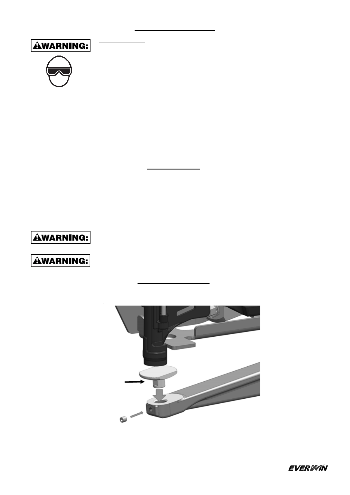
REPLACE ANVIL
Please be advised that the Anvil is replaceable, please see the explanation below.
Flat surface
face front
Add Loctite 243 or equivalent to
bolt before assembly

11
TOOL OPERATION CHECK
CAUTION: Remove all fasteners from tool before performing tool operation check.
a. With finger off the trigger, press the contact trip against the work surface.
THE TOOL MUST NOT CYCLE.
b. With finger off the trigger, press the secondary trigger.
THE TOOL MUST NOT CYCLE.
c. Hold the tool off the work surface without depressing second trigger, and pull the trigger.
THE TOOL MUST NOT CYCLE.
d. Hold the tool on the work surface, depress secondary trigger, and pull the trigger.
THE TOOL MUST CYCLE.
IN ADDITION TO THE OTHER WARNINGS CONTAINED IN THIS MANUAL OBSERVE THE FOLLOWING
FOR SAFE OPERATION
l
Use this pneumatic tool only for the purpose for which it was designed like pallet, crating,
sheathing, decking applications
l
Never use this tool in a manner that could cause a fastener to be directed toward the user or others
in the work area.
l
Do not use the tool as a hammer.
l
Always carry the tool by the handle. Never carry the tool by the air hose.
l
Do not carry this tool with the trigger depress when not in use
.
l
Do not alter or modify this tool from the original design or function.
l
Always be aware that misuse and improper handling of this tool can cause injury to yourself and
others.
l
Never clamp or tape the trigger or contact trip in an actuated position.
l
Never leave a tool unattended with the air hose attached.
l
Do not operate this tool if it does not contain a legible WARNING LABEL.
l
Do not continue to use a tool that leaks air or does not function properly. Notify your
distributor or representative if your tool continues to experience functional problems.
12
MAINTAINING THE PNEUMATIC TOOL
When working on air tools, note the warnings in this manual and use extra care
evaluating problem tools. Disconnect air supply and empty the magazine when
inspecting or maintaining the tool.
REPLACEMENT PARTS:
Use only genuine parts from the manufacturer or distributor. Do not use modified parts or parts which will not give
equivalent performance to the original equipment.
Tighten all screw.
Keep contact arm moving smoothly.
ASSEMBLY PROCEDURE FOR SEALS:
When repairing a tool, make sure the internal parts are clean and lubricated. Use Parker “O”-LUBE or equivalent
on all “O”-rings. Coat each “O”-ring with “O”-LUBE before assembling. Use a small amount of oil on all moving
surfaces and pivots. After reassembly add a few drops of Air Tool Lubricant through the air line fitting before testing.
AIR PRESSURE AND VOLUME:
Air volume is as important as air pressure. The air volume supplied to the tool may be inadequate because of undersize
fittings and hoses, or from the effects of dirt and water in the system. Restricted air flow will prevent the tool from
receiving an adequate volume of air, even though the pressure reading is high. The results will be slow operation,
misfeeds or reduced driving power. Before evaluating tool problems for these symptoms, trace the air supply from
the tool to the supply source for restrictive connectors, swivel fittings, low points containing water and anything else
that would prevent full volume flow of air to the tool.
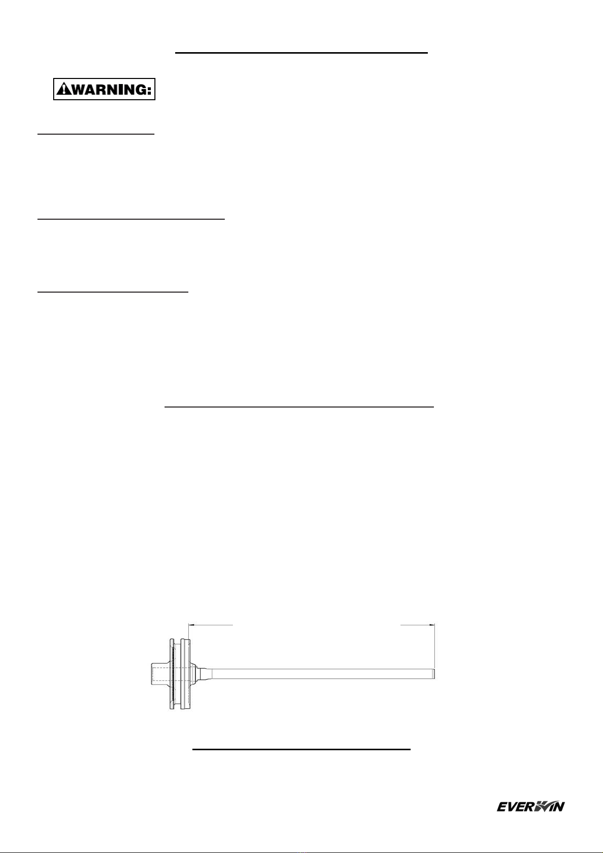
DRIVER MAINTENANCE INSTRUCTIONS
Worn driver causing poor quality or loss of power:
Wear on the driving tip will affect the nail drive, giving symptoms of bent and incompletely driven nails, and damaged
nail heads.
The driver length may be adjusted to allow the driving tip to be redressed to compensate for wear. Heat and precise
measurement are required. Contact a qualified service technician for this adjustment.
The length setting for a new driver is shown below. Measurement is from the bottom face of the main piston.
Note that the measurement from the top of the piston gives the maximum amount the driver may be adjusted to allow
redressing. Always extend the driver the minimum required to allow redressing to restore the driving end; several re-
dressings will be possible before this maximum depth is reached.
When using optional flangeless driver, see adjustment below. Be sure to use proper preparation and installation.
TROUBLESHOOTING / REPAIRS
The troubleshooting and / or repairs shall be carried out only by the authorized dealer / distributor
or
by other
pneumatic tool specialists.
Standard Length
5.630” – 5.654” (143.0 – 143.6 mm)
Table of contents
Other Everwin Nail Gun manuals

Everwin
Everwin ECAR-S User manual

Everwin
Everwin FSN130B User manual

Everwin
Everwin FN1850 User manual

Everwin
Everwin FSN130 User manual

Everwin
Everwin SCN65B-CM User manual

Everwin
Everwin CFN-15S User manual

Everwin
Everwin MCN40 User manual
 User manual")
Everwin
Everwin FSN2283A(AD) User manual

Everwin
Everwin AFN1565 User manual

Everwin
Everwin FSN2283 Series User manual


