EVGA X299 FTW-K User manual

EVGA X299 FTW - K (142-SX-E297)
- 1 -
User Guide
EVGA X299 FTW-K
Specs and Initial Installation

EVGA X299 FTW - K (142-SX-E297)
- 2 -
Table of Contents
User Guide ............................................................................................................... - 1 -
EVGA X299 FTW-K ................................................................................................. - 1 -
Specs and Initial Installation..................................................................................... - 1 -
Before You Begin… ................................................................................................. - 4 -
Parts NOT in the Kit............................................................................................................. - 5 -
Intentions of the Kit.............................................................................................................. - 5 -
Motherboard Specifications.................................................................................................. - 6 -
Unpacking and Parts Descriptions........................................................................................ - 8 -
Intel X299 FTW-K Motherboard LED reference ................................................................. - 9 -
Intel X299 FTW-K Motherboard Component Legend ....................................................... - 12 -
PCI-E Slot Breakdown ....................................................................................................... - 24 -
M.2 and U.2 Slot Breakdown ............................................................................................. - 25 -
Installing the CPU .................................................................................................. - 26 -
Installing the CPU Cooling Device .................................................................................... - 27 -
Installing System Memory.................................................................................................. - 28 -
Installing the I/O Shield and I/O Cover.............................................................................. - 29 -
Installing the Motherboard...................................................................................... - 29 -
Securing the Motherboard into a System Case................................................................... - 30 -
Installing M.2 devices......................................................................................................... - 32 -
Tested CPU......................................................................................................................... - 35 -
Tested U.2........................................................................................................................... - 35 -
Tested M.2 Key-M ............................................................................................................. - 36 -
Tested M.2 Key-E............................................................................................................... - 36 -
Connecting Cables.............................................................................................................. - 37 -
Onboard Buttons................................................................................................................. - 47 -
First Boot ................................................................................................................ - 48 -
M.2 SSD, PCI-E SSD, and NVMe SSD Installation steps ................................................. - 50 -

EVGA X299 FTW - K (142-SX-E297)
- 3 -
Internal RAID Controller ......................................................................................... - 52 -
Fan Header DC and PWM setup ........................................................................... - 87 -
Setting Up SLI and PhysX...................................................................................... - 91 -
Realtek HD Audio Manager ............................................................................................... - 95 -
Configuration of the Killer NIC Software .............................................................. - 113 -
Installing Drivers and Software ............................................................................ - 131 -
Windows 10 Driver Installation........................................................................................ - 131 -
Warranty and Overclocking.............................................................................................. - 132 -
Troubleshooting ................................................................................................... - 133 -
Replacing a BIOS chip ..................................................................................................... - 133 -
SSD / HDD is not detected ............................................................................................... - 136 -
System does not POST, and POST code indicator reads “C”........................................... - 138 -
System does not POST, and POST code indicator reads “55” ......................................... - 139 -
System does not POST, and POST code indicator reads “d7” ......................................... - 139 -
Have a question not covered above, or want some online resources? .............................. - 140 -
POST Beep codes ............................................................................................................. - 141 -
POST Port Debug LED .................................................................................................... - 142 -
POST Codes ........................................................................................................ - 143 -
EVGA Glossary of Terms ................................................................................................ - 148 -
Compliance Information ....................................................................................... - 151 -

EVGA X299 FTW - K (142-SX-E297)
- 4 -
Before You Begin…
EVGA welcomes you to the next generation of Intel Enthusiast performance:
the 299 FTW-K! The 299 platform supports the newest Skylake- and
Kaby Lake- processors. EVGA 299 motherboards further refine high-
performance with multiple options for all the latest SSD options with support
for U.2, M.2 and PCI-E drives and is Intel
®
Optane™ Memory Ready – a
revolutionary higher-density memory interface, based on 3D Point
Technology, delivers a new generation of SSDs designed to obliterate loading
times for gamers. However, the 299 platform also supports all the features
you’ve come to expect from EVGA, including up to 128GBs of Quad-Channel
DDR4 memory at maximum memory speeds of up to 4000MHz+for Skylake-
, and 4133MHz+ for Kaby Lake- (OC), Gigabit-NIC support, USB 3.0 and
USB 3.1 Type-A and Type-C support, an updated UEFI\BIOS GUI, PWM fan
control and a variety of SATA options to fit everyone’s needs. The 299 FTW-
K is built with a 8-layer PCB, featuring a CPU socket with 150% higher Gold
content powered by an Advanced 14-phase Digital VRM (10 Phase VCore, 4
Phase Memory PWM), providing industry-leading stability for all your
applications.
Furthermore, this board is designed not ONLY for overclockers, but also for
gamers with NVIDIA® 3-Way SLI + Phys Support without the need for PL
chips, blazing-fast networking featuring the Killer E2500 NIC and an Intel i219,
Dual M.2 Key-M, Dual U.2, 8 SATA 3/6g and much more!
Lastly, a motherboard is only as good as its BIOS, and the EVGA 299 FTW-
K features an updated UEFI\BIOS GUI with a focus on overclocking and
functionality in a lean, straight-forward package. You won’t need to be an
expert to configure your motherboard, but if you are, you’ll find features
unavailable anywhere else.
Combining the best of current technology with the latest innovations, EVGA is
further refining motherboard performance!

EVGA X299 FTW - K (142-SX-E297)
- 5 -
Parts NOT in the Kit
This kit contains all the hardware necessary to install and connect your new
EVGA 299 FTW-K Motherboard. However, it does NOT contain the
following items, which must be purchased separately in order to make the
system fully-functional and install an Operating System:
Intel Socket 2066 Processor
DDR4 System Memory
CPU Cooling Device
PCI xpress Graphics Card
Power Supply
Hard Drive or SSD
Keyboard / Mouse
Monitor
(Optional) Optical Drive
EVGA assumes you have purchased all the necessary parts needed to allow for
proper system functionality. For a full list of supported CPUs on this
motherboard, please visit www.evga.com/support/motherboard
Intentions of the Kit
When replacing a different model motherboard in a PC case, you may need to
reinstall your operating system, even though the current HDD/SSD may
already have one installed. Keep in mind, however, you may sometimes also
need to reinstall your OS after a RMA even if your motherboard remains the
same due to issues that occurred prior to replacing the motherboard.

EVGA X299 FTW - K (142-SX-E297)
- 6 -
Motherboard Specifications
Size:
EAT form-factor of 12 inches x 10.375 inches (304.8x276.7mm)
Microprocessor support:
Intel Socket 2066 Processor
Operating Systems:
Supports Windows 10 64bit only
System Memory support:
Supports Quad Channel DDR4 up to 4000MHz+ Skylake- , and 4133MHz+
Kaby Lake- (OC).
Supports up to 128GB of DDR4 memory.
USB 2.0 Ports:
4x from Intel 299 PCH – 4x internal via 2 FP headers
Supports transfer speeds up to 480 Mbps with full backwards compatibility
USB 3.0 Ports:
8x from Intel 299 PCH – 6x external, 2x internal via 1 FP headers
Supports transfer speeds up to 5Gbps with full backwards compatibility
USB 3.1 Ports:
2x from ASMedia ASM2142 – 2x external, 1x Type-C, 1x Type-A
Supports transfer speeds up to 10Gbps with full backwards compatibility
*Type-C will require a Type-A adapter for backwards compatibility
SATA Ports:
Intel 299 PCH Controller
8x SATA 3/6G (600 MB/s) data transfer rate
- Support for RAID0, RAID1, RAID5, AND RAID10
- Supports hot plug
Onboard LAN:
1x Intel i219v Gigabit (10/100/1000) Ethernet
1x Killer E2500 Gigabit (10/100/1000) Ethernet MAC+PHY
Ethernet Teaming NOT Supported
Killer Doubleshot Pro supported with Killer Wireless AC 1535 or 1525
* Killer Wireless AC is NOT included and must be purchased separately

EVGA X299 FTW - K (142-SX-E297)
- 7 -
Onboard Audio:
Realtek Audio (ALC1150)
Supports 8-channel (7.1) audio with Optical S/PDIF Out
Power Functions:
Supports ACPI (Advanced Configuration and Power Interface)
Supports S0 (normal), S3 (suspend to RAM), S4 (Suspend to disk - depends
on OS), and S5 (soft - off)
PCI- xpress xpansion Slots:
4x PCI-E x16 slot 2x16, 2x8*
1x PCI-E x4 slot
1x PCI-E x1 slot
*LANES PER SLOT CAN VARY BASED OFF OF CPU, PLEASE SEE
PAGE 24 FOR LANE BREAKDOWN BASED OFF OF CPU.
PCI- 3.0 Support:
Low power consumption and power management features
SLI and Crossfire Support:
3-Way SLI
3-Way Crossfire
Additional xpansion Slots:
1x M.2 Key-M 110mm slot PCI-E/NVMe
1x M.2 Key-M 80mm slot PCI-E/NVMe & SATA/Optane
Key-M 80mm Supports Intel Optane
1x M.2 Key-E slot (via vertical adapter)
2x U.2 slot
RGB L D Header:
4x 4-pin RGB LED header (For included RBG lit covers ONLY)
VROC Header:
1x 4-pin VROC header
Fan Headers:
2x 4-pin PWM controlled headers
5x 4-pin DC\PWM headers
-3pin(DC)\4pin(PWM) modes are selected and static RPM set in BIOS
ALL FAN H AD RS HAV A MAXIMUM POW R OF
1 AMP @ 12 VOLTS (12 WATTS) XC DING THIS LIMIT
WILL CAUS TH BOARD IRR PARABL DAMAG .
EVGA X299 FTW - K (142-SX-E297)
- 8 -
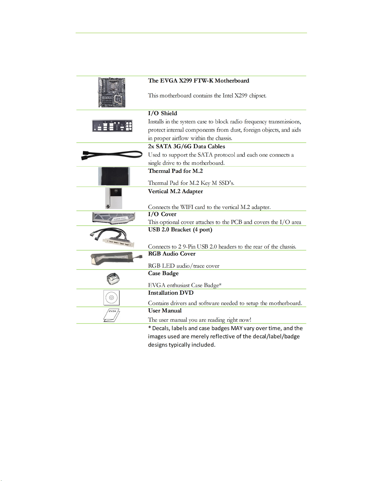
Unpacking and Parts Descriptions
The following accessories are included with the EVGA 299 FTW-K
Motherboard:
EVGA X299 FTW - K (142-SX-E297)
- 9 -
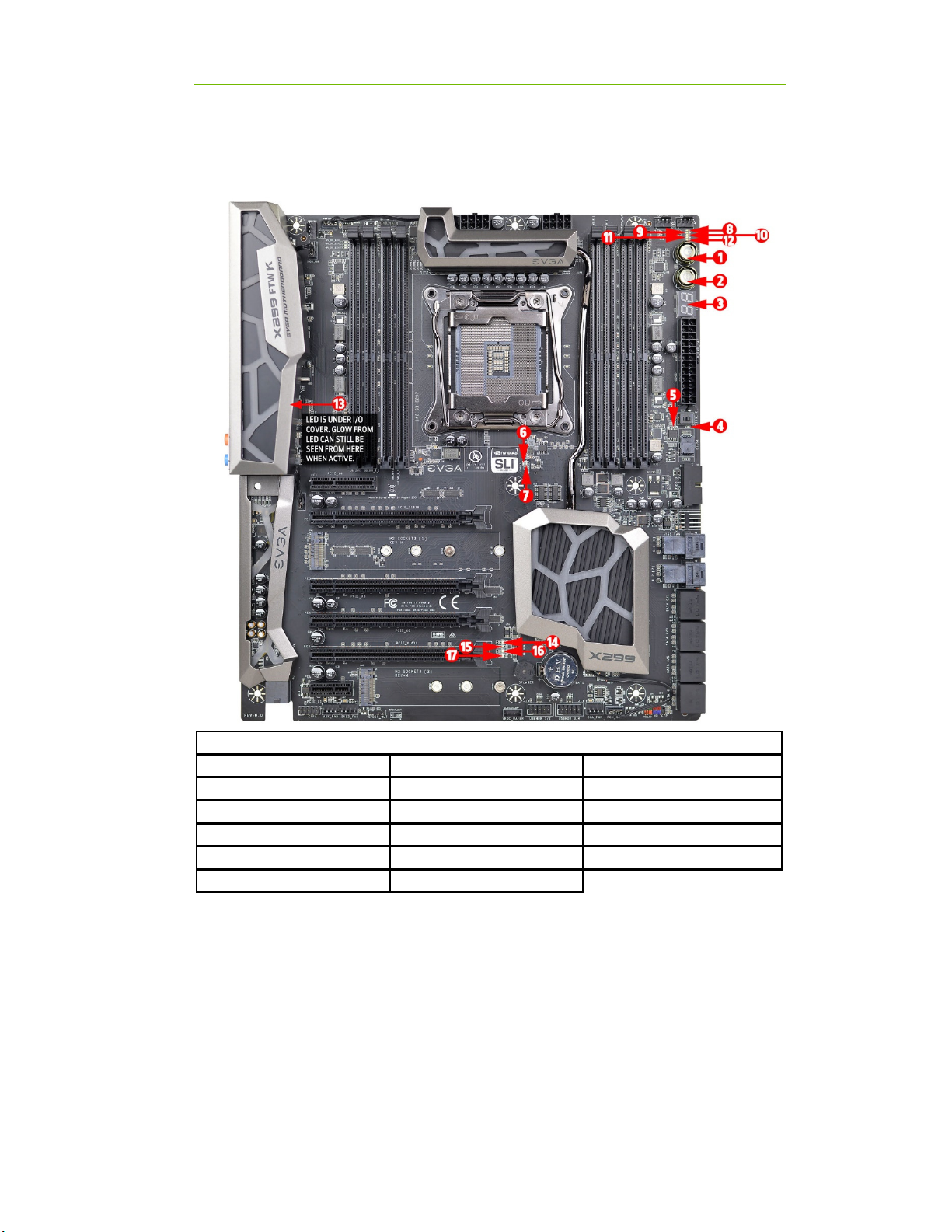
Intel X299 FTW-K Motherboard LED reference
The EVGA 299 FTW-K Motherboard has several LEDs indicating power, connectivity,
and activity. Below is the location of the LEDs and their function.
1.
Power Button
7.
CATERR
13.
CC_LED
2.
Reset Button
8.
VSM
14.
PE2 Status/Mo e
3.
POSTCODE In icator
9.
VCC
15.
PE3 Status/Mo e
4.
Removable BIOS LED 1
10.
5VSB
16.
PE4 Status/Mo e
5.
Non-Removable BIOS LED 2
11.
SKX Detect
17.
PE5 Status/Mo e
6.
FIVR
12.
KBX Detect
LED Legend

EVGA X299 FTW - K (142-SX-E297)
- 10 -
1. Power Button
a. RED: System is on
b. GREEN (blinking): System in Sleep mode
2. Reset Button
a. WHITE: blinks with storage access
3. POST Code indicator
a. After bootup, this will display the CPU temp.
b. During boot it will cycle many different hexadecimal post codes with a
range of 00-FF and this indicates what aspect of the Power On Self Test
(POST) is currently running.
i. *For list of POST Codes, please see Page 142.
4. Removable BIOS LED
a. RED: Active BIOS Chip (only 1 will be lit at a time)
b. This LED indicates the removable BIOS chip is active
5. Non-Removable BIOS LED
a. RED: Active BIOS Chip (only 1 will be lit at a time)
b. This LED indicates the non-removable BIOS chip is active
6. FIVR
a. RED: Indicates CPU integrated voltage regulation failure.
b. OFF: No issues detected on FIVR
7. CATERR
a. CATERR stands for Catastrophic Error on the processor.
b. RED: Processor error has occurred.
c. Off: No error state detected in the CPU.
8. VSM
a. YELLOW: Voltage detected (
Does not mean PSU is
outputting in-spec, only that this specific voltage is
detected
)
9. VCC
a. RED: Voltage detected (
Does not mean PSU is outputting in-
spec, only that this specific voltage is detected
)
10. 5VSB
a. WHITE: Voltage detected (
Does not mean PSU is outputting
in-spec, only that this specific voltage is detected
)
11. SK LED
a. YELLOW: Indicates a SkyLake- processor is installed into the socket.
12. KB LED
a. WHITE: Indicates a Kaby Lake- processor is installed into the socket.

EVGA X299 FTW - K (142-SX-E297)
- 11 -
13. CC_LED
a. USB 3.1 Type-C detection.
b. RED: Indicates device is attached and detected to USB Type-C.
c. OFF: No device detected.
14. PCI-Express LED for PE2. The LED will remain off when this PCI-E slot is
disabled or unpopulated.
a. GREEN: Operating at PCI-Express Gen1 speed
b. YELLOW: Operating at PCI-Express Gen2 speed
c. RED: Operating at PCI-Express Gen3 speed
15. PCI-Express LED for PE3. The LED will remain off when this PCI-E slot is
disabled or unpopulated.
a. GREEN: Operating at PCI-Express Gen1 speed
b. YELLOW: Operating at PCI-Express Gen2 speed
c. RED: Operating at PCI-Express Gen3 speed
16. PCI-Express LED for PE4. The LED will remain off when this PCI-E slot is
disabled or unpopulated.
a. GREEN: Operating at PCI-Express Gen1 speed
b. YELLOW: Operating at PCI-Express Gen2 speed
c. RED: Operating at PCI-Express Gen3 speed
17. PCI-Express LED for PE5. The LED will remain off when this PCI-E slot is
disabled or unpopulated.
a. GREEN: Operating at PCI-Express Gen1 speed
b. YELLOW: Operating at PCI-Express Gen2 speed
c. RED: Operating at PCI-Express Gen3 speed
EVGA X299 FTW - K (142-SX-E297)
- 12 -
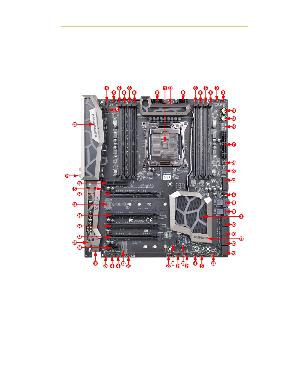
Intel X299 FTW-K Motherboard Component
Legend
The EVGA 299 FTW-K Motherboard with the Intel 299 and PCH Chipset.
Figure 1 shows the motherboard and Figure 2 shows the back panel connectors
FIGUR 1. X299 FTW-K Motherboard Layout
EVGA X299 FTW - K (142-SX-E297)
- 13 -
**For a FULL description of the above legend, please see Page 15.
1.
CPU Socket 2066
12.
M.2 Socket 3 Key-M 110mm
23.
RGB Backlit Component Covers
2.
Intel X299 PCH (Southbri ge)
13.
M.2 Socket 3 Key-M 80mm
24.
Front Panel Au io Connector
3.
CPU Fan Hea ers (1 amp PWM)
14.
PCI-E Slot 16x/8x
25.
Front Panel Connectors
4.
Fan Hea ers (1 amp DC/PWM)
15.
PCI-E Slot 4x
26.
S/PDIF Out
5.
RBG LED Controller Hea er
16.
PCI-E Slot 1x
27.
Removable BIOS Chip
6.
DDR4 Memory DIMM Slots 1-8
17.
Power Button
28.
BIOS Selector Switch
7.
24-pin ATX power connector
18.
Reset Button
29.
CMOS Battery
8.
8 pin EPS Connector
19.
Debug LED / CPU Temp Monitor
30.
PC Speaker
9.
Supplimental PCI-E 6 pin power
20.
USB 3.0 Hea ers
31.
Rear Panel Connectors (Figure 2)
10.
Intel Sata 6G RAID Ports
21.
USB 2.0 Hea ers
11.
U.2 (SFF-8639) Port
22.
VROC Hea er
Component Legend

EVGA X299 FTW - K (142-SX-E297)
- 14 -
Figure 2. Chassis Rear Panel Connectors
1.
USB 3.0
4.
BIOS/CMOS Reset
7.
M.2 Key-E Vertical Hea er
2.
USB 3.1 type A
5.
Killer E-2500 NIC
8.
Optical Out
3.
USB 3.1 type C
6.
Intel I 219 NIC
9.
Analog Au io Jacks
I/O Hub
Blue Line in Line In Line in * Rear Speaker Out
Pink Mic In Mic In Mic In Mic In
Black Si e Speaker Out Si e Speaker Out Si e Speaker Out
Orange Center/Sub Out Center/Sub Out
3.5mm Audio Jack Legend
Analog Audio
Port reakdown
* 7.1 output is enable via Realtek Software from within Win ows. (Page 95)
2/2.1 Channel 4.0/4.1 Channel 5.1 (6 Channel) 7.1 (8 Channel)
Green Front Speaker Out/
Front Speaker + Sub
Front Speaker Out/
Front Speaker + Sub
Front Speaker
Out Front Speaker Out

EVGA X299 FTW - K (142-SX-E297)
- 15 -
Component Legend Descriptions
1. CPU Socket 2066
This is the interface for the Central Processing Unit (CPU), and supports Core
i7 models compatible with the Intel 2066 Socket Skylake- and Kaby Lake-
architecture.
2. Intel 299 PCH (Southbridge)
The Platform Controller Hub (PCH) handles the role that was previously held
by the South Bridge. The PCH has 4 PCI-E Gen 3 lanes and allocates
bandwidth to smaller PCI-E slots, M.2 Key-E, USB, audio, etc. In simplified
terms, the PCH works as a hub for peripherals that are less bandwidth-
intensive.
3. CPU Fan Headers (PWM)
4-pin fan headers that control the fan speed based on a configurable curve or
static percentage. PWM (Pulse-Width Modulation) works by pulsing power to
the fan at a constant rate and sending the RPM signal to the fan’s controller via
a Sense cable, rather than adjusting fan speed by increasing and decreasing
voltage. This method is preferable because it eliminates voltage-based fan stall
points. Please see Page 87 for more in-depth PWM breakdown and PWM
controls within BIOS/UEFI.
4. Fan Headers DC/PWM
These ports are simply toggled between DC and PWM to be compatible with 3
pin and 4 pin fans. The fans will be set to a static percentage set in BIOS.
5. RGB Header
The RBG header is a 4 pin header that allows a software based control within
windows for RGB devices via ELEET- . Please see Page 42 for control
specifics.
6. DDR4 Memory Slots
The memory slots support up to four 288-pin DDR4 DIMMs in Quad-Channel
mode with Skylake- processors; and supports up to two 288-pin DDR4
DIMMs in Dual-Channel mode with Kaby Lake- processors.
Skylake- processors are certified for Quad-Channel mode, and will be enabled
only upon using four sticks of supported memory, according to the installation
guide on Page 28. Skylake- supports up to 128GB (8x16GB) up to
4000MHz+, 32GB modules are *NOT* supported on this platform. Some

EVGA X299 FTW - K (142-SX-E297)
- 16 -
Dual-Channel kits *may* work; however Skylake- is certified for Quad-
Channel operation, not Dual-Channel. Dual-Channel configurations will
substantially reduce the potential memory bandwidth of the Skylake-
processor.
Kaby Lake- processors are certified for Dual-Channel mode, and will be
enabled only upon using two sticks of supported memory, according to the
installation guide on Page 28. Kaby Lake- supports up to 64GB (4x16GB) up
to 4133MHz+. 32GB modules are *NOT* supported on this platform. Some
Quad-Channel kits *may* work, however Kaby Lake- is not certified for
Quad-Channel operation, only Dual-Channel, and will gain no benefit from
Quad-Channel over Dual-Channel.
Using an odd number of DIMMs (1,3,5,7) will lower the board to Single-
Channel mode, which may significantly lower performance depending on the
application.
The speeds listed above cannot be guaranteed as Intel
®
only certifies the speed
of the memory controller up to 2666/2400MHz for Kaby Lake- and Skylake-
platforms respectively, and all speeds above the speeds certified by Intel
®
require overclocking.
7. 24-pin AT power connector
The main power for the motherboard is located on the right side of the board
and perpendicular to the PCB; this is also described as a “Vertical” connector
(See Page 38 for more specifics to the connector itself, and associated
wiring/pinouts). The 24-pin connector IS directional and the connector needs
the tab on the socket to line up with the release clip located on the 24-pin
connector from the power supply. This connector pulls the bulk of the power
for all components; other connectors, such as EPS, PCI-E (video card AND
motherboard sides), have been added to reduce the load and increase longevity
due to wiring and trace limitations.
8. 8-pin EPS Connector
The EPS is dedicated power for the CPU (See Page 39 for more specifics to the
connector itself, and associated wiring/pinouts). Carefully choose the correct
power cable by consulting with the installation manual for your power supply.
This connector is designed only to work with an EPS or CPU cable. System
builders may make the mistake of plugging in a PCI-E 8-pin or 6+2-pin
connector, which will prevent the board from POSTing and possibly damage
the board; although the cables appear similar, they are wired differently and
attaching a PCI-E cable to an EPS connector may cause damage to the
motherboard.

EVGA X299 FTW - K (142-SX-E297)
- 17 -
Alternatively, if no power cable is connected or detected, the system will not
POST and will hang at POST code “C.”
9. Supplemental PCI-E 6-pin Power Connector
There is a 6-pin PCI-E connector at the bottom of the motherboard (See page
38 for more specifics to the connector itself, and associated wiring/pinouts).
This connector provides dedicated power to the PCI-E x16 slots, augmenting
the power provided by the 24-pin and the GPU directly.
This is optional for a single card solution, and is recommended for SLI, CF ,
and dual processor video cards.
10. Intel SATA 3/6G Ports
The Intel 299 PCH has a 8-port SATA 3/6G controller (See Page 46 for
specifics on the connectors). This controller is backwards-compatible with
SATA and SATA 2 devices, and supports SSDs, HDDs and various types of
optical devices (CDROM, DVDROM, BD-ROM, etc). The controller also
supports NCQ, TRIM, hot swap capability (provided the proper HDD/SSD
bays/racks are installed), and RAID levels 0/1/5/10.
11. U.2 Port (SFF-8639)
U.2, originally known as SFF-8639, is a high bandwidth connection specifically
engineered for next generation SSD’s. U.2 brings PCI-E x4 (Gen3) NVMe
performance to a 2.5” SSD form factor and provides a solution to potential
heating problems that may be present in some M.2 solutions.
12. M.2 Socket 3 Key-M 110mm
M.2 is a SSD standard, which uses up to four PCI-E lanes and utilizes Gen3
speeds. Most popularly paired with NVMe SSDs, this standard offers
substantially faster transfer speeds and seek time than SATA interface
standards. All M.2 devices are designed to connect via a card-bus style
connector and be bolted into place and powered by the connector, rather than
by a dedicated data cable and power cable.
This socket will support Key-M devices of 110mm, 80mm, 60mm, and 42mm
length.
This connector can utilize either a PCI-E/NVMe based M.2 SSD or SATA M.2.
13. M.2 Socket 3 Key-M 80mm
M.2 is a SSD standard, which uses up to four PCI-E lanes and utilizes Gen3
speeds. Most popularly paired with NVMe SSDs, this standard offers
substantially faster transfer speeds and seek time than SATA interface
standards. All M.2 devices are designed to connect via a card-bus style

EVGA X299 FTW - K (142-SX-E297)
- 18 -
connector and be bolted into place and powered by the connector, rather than
by a dedicated data cable and power cable.
This socket will support Key-M devices of 80mm, 60mm, and 42mm length.
This connector can utilize either a PCI-E/NVMe based M.2 SSD, SATA M.2,
or Intel Optane devices.
14. PCI-E Slot x16/x8*
PCI-E x16/x8 slots are primarily for video cards. These full-length slots will
provide 8 or 16 lanes of bandwidth to a full-size card, and are backwards-
compatible with x8, x4, and x1-length cards.
Skyake- Socket 2066 processors have 44 or 28 PCI-E lanes available for
routing, whereas Kaby Lake- has 16 PCI-E lanes.
15. PCI-E Slot x4*
PCI-E x4 slot uses up to 4 Gen 3 lanes from the PCH. This slot is typically
used for sound cards, WiFi, USB, or other peripheral cards.
Because this slot uses PCH bandwidth, this will have *NO EFFECT* on the
bandwidth or throughput of the x16 slots used for SLI.
16. PCI-E Slot x1*
PCI-E 1x is the smallest form-factor PCI-E card slot. They are all one lane and
are used for low-bandwidth products. This slot uses 1 lane from the PCH.
17. Power Button
This is an onboard power button, and may be used in place of, or in
conjunction with, a front panel power button wired to the board.
Benching systems, or test benches before final assembly, are best served by
using the onboard power because it removes the need to wire a Power/Reset
button or cross posts with a screwdriver, which is a semi-common practice.
This button provides a safer and easier option than jumpering the Power posts.
18. Reset Button
This is an onboard system reset button, and may be used in place of, or in
conjunction with, a front panel system reset button wired to the board.
Benching systems, or test benches before final assembly, are best served by
using the onboard power because it removes the need to wire a Power/Reset
button or cross posts with a screwdriver, which is a semi-common practice.
This button provides a safer and easier option than jumpering the Power posts.
19. Debug LED / CPU Temp
This is a two-digit POST code reader, displaying in hexadecimal, which means
the characters available (when working as intended) are 0-9, A-F and has a cap
of 255 characters. The POST codes are listed in the troubleshooting section on

EVGA X299 FTW - K (142-SX-E297)
- 19 -
Page 142. After the system boots, it will display the temperature in Celsius.
This temperature is specifically for the CPU socket, which will typically read
slightly higher than a given CPU core. To read this temp in Fahrenheit, take the
value in Celsius, multiply by 9/5 (or 1.8) and add 32.
20. USB 3.0 Headers
The USB3.0 headers are used to connect additional USB interface plugs to the
motherboard; these headers are most often used to connect the motherboard to
the chassis to enable the USB3.0 ports on the chassis. These will function the
same as the USB3 ports found on the motherboard’s hardwired I/O hub, but
these can be used to attach to front panel USB, auxiliary ports that mount in the
card slots, and also some devices that directly connect to the header.
USB 3.0 standard is 900ma @ 5V for unpowered devices. If your USB device
requires more power than this, it is recommended to attach a powered USB
Hub.
USB 3.1 Type-A (found on the I/O Hub) shares the power limit of USB 3.0 at
900ma @ 5V. Whereas USB 3.1 Type-C (also found on the IO Hub) has a
power limit of 3000ma (3A) @ 5V.
21. USB 2.0 Headers
The USB2.0 header is used to connect additional USB interface plugs to the
motherboard; these headers are most often used to connect the motherboard to
the chassis to enable the USB2.0 ports on the chassis. These will function the
same as the USB2 ports found on the motherboard’s hardwired I/O hub, but
these can be used to attach to front panel USB, auxiliary ports that mount in the
card slots, and also some devices that directly connect to the header.
USB 2.0 standard is 500ma @ 5V per port (header total is 1000ma) for
unpowered devices. If your USB device requires more power than this, it is
recommended to attach a powered USB Hub.
22. VROC Header
VROC stands for Virtual RAID On CPU, the VROC headers works in
conjunction with the upcoming VROC cards. VROC cards are 4 device M.2
Key-M cards for PCI-E that allow RAID functions on the card. The Header is
for an Intel hardware key that will unlock advanced RAID functions, which in
VROC’s case is anything other than RAID0.
Important note, as of the time this manual was written, VROC will work with
many SSD’s but is only bootable with Intel SSD’s. Also VROC is only
compatible with Skylake- CPUs

EVGA X299 FTW - K (142-SX-E297)
- 20 -
23. RGB Backlit Panels
These panels sit on top of other components, such as heatsink, and provide
RGB LED lighting. These panels connect to the RGB Headers (component
#5) and provide stylized backlighting which can be controlled in EVGA
ELEET- .
These RBG Headers are ONLY to be used for the included/preattached RBG
covers, not a 3
rd
party RGB device.
24. Front Panel Audio Connector
This is a motherboard header, which is used to plug in the audio cable
originating from most PC chassis to allow audio to be recorded from or played
through the audio connectors on the chassis. This header has a connector that
looks similar to USB2 and will use the standard “HD Audio” jack. Some cases
may have two headers on one cable strand: one labeled HD Audio, and one
labeled AC’97 – this header is not compatible with AC’97.
25. Front Panel Connectors
The Front panel connectors are the four main chassis connections. These
include the Power Switch, Power LED, Reset Switch, and HDD LED. The
Power and Reset switches are both designed to use “Momentary Switches,”
rather than “Latching Switches,” which means the connection between the two
posts needs to be made just briefly for it to work, as opposed to being held in
place. This is why the Power and Reset switches can be triggered with a screw
driver by simultaneously touching the + and - posts.
Power LED will power on with the system, indicating the system is on and can
blink with CPU activity.
HDD LED will blink during access to the SATA ports, U.2 port, and/or the
M.2 Key-M SSD’s.
26. S/PDIF Out
S/PDIF is used for audio pass-through, which is used on some older video
cards, video capture cards, and some older generation devices. This port is not
widely used now, but is here in case a legacy item requires the connector. Most
of the audio data is pushed through the bus now, and does not require an
external cable. NOTE: This is a S/PDIF Out connector, and cannot operate to
record data from an external device.
27. Removable BIOS Chip
The ability to remove and replace the BIOS chip without requiring special tools
is a key feature on many of our boards, by adding a level of protection against
BIOS failures, bad BIOS flashes, BIOS corruption, etc. This feature also allows
EVGA to work with end-users if something happens to render the BIOS chip
unusable or a BIOS update is needed for CPU compatibility; rather than
Table of contents
Other EVGA Motherboard manuals

EVGA
EVGA Classified SR-2 Super Record 2 System manual

EVGA
EVGA 160-SB-E689-KR User manual

EVGA
EVGA X79 Classified User manual

EVGA
EVGA X79 Classified User manual

EVGA
EVGA 111-CD-E630-TR User manual

EVGA
EVGA nForce 780i SLI FTW User manual

EVGA
EVGA X58 FTW User manual

EVGA
EVGA P55 LE User manual

EVGA
EVGA Z68 FTW User manual

EVGA
EVGA Z97 User manual

EVGA
EVGA 120-LF-E650-TR User manual

EVGA
EVGA EVGA X79 DARK System manual

EVGA
EVGA Z390 FTW User manual

EVGA
EVGA Z390 DARK User manual

EVGA
EVGA Z87 System manual

EVGA
EVGA X299 Micro ATX 2 User manual

EVGA
EVGA Z68 SLI Micro User manual

EVGA
EVGA 112-CK-NF72-K1 User manual

EVGA
EVGA X79 FTW User manual

EVGA
EVGA Z77 FTW User manual


